

How to guide
Updated: Tuesday, December 14th 2021
MachineLogic for Universal Robots (URCap v3.x)
Compatible with MachineMotion Controller V1E0 and Polyscope version 5
Overview
Vention offers Universal Robot Capability (URCap) extension packages which enable simple programming of Vention motion systems from the UR teach pendant. Once loaded in the UR Polyscope HMI, URCap integrations make it simple and cost-effective to create systems combining UR six-axis robot arms with Vention’s MachineMotion-controlled components.
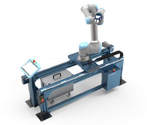
This document describes MachineLogic for Universal Robots, a URCap that enables seamless integration of motion components such as enclosed linear axis, ball-screw linear axis, rack-and-pinion linear axis, pneumatic systems, and roller & belt conveyors. Once connected to a UR six-axis robot arm, those components enable applications like range extenders, cobot palletizers and other custom robot cells.
1. Install the URCap
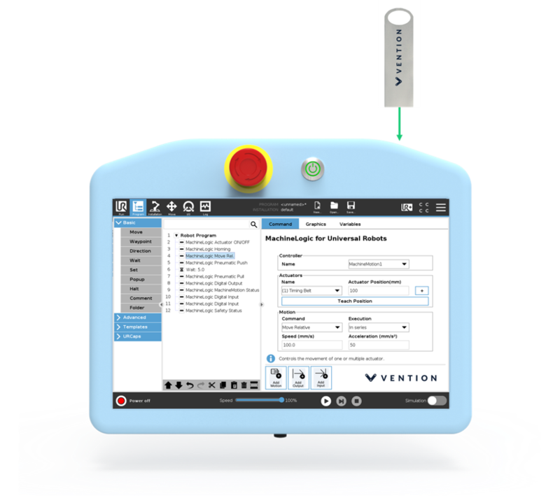
Step 1: Insert the USB drive
Vention’s MachineLogic for Universal Robots software is distributed on a USB flash drive and must be installed on the UR teach pendant. To install the URCap, insert the USB drive into the UR teach pendant’s USB port.
Step 2: Add the URCap to the UR environment
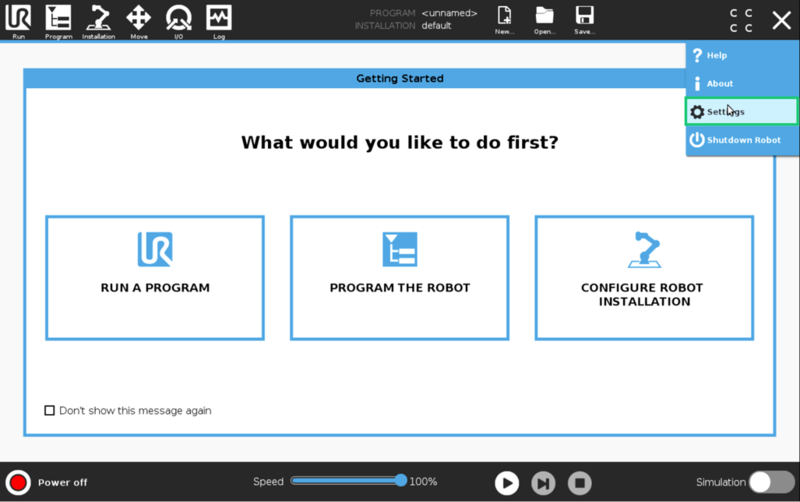
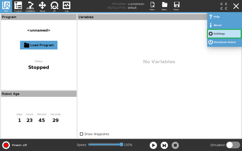
On the teach pendant home screen, select Menu > Settings (see Figure 3a).
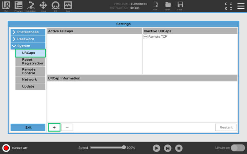
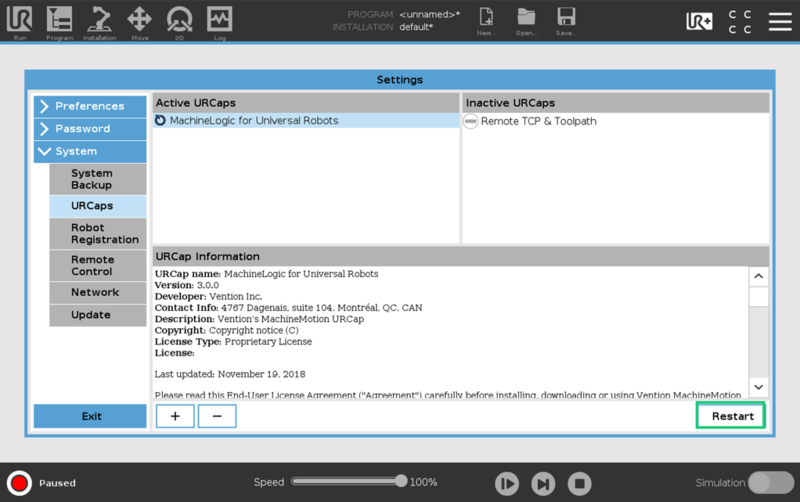
Select System > URCaps, then click the + icon at the bottom of the screen to add a new URCap to the UR teach pendant (see Figure 3b).
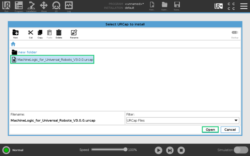
Select the .urcap file and click Open to install the URCap extension (see Figure 4a).
Step 3: Restart the UR controller
When prompted to do so, restart the UR controller to complete the installation (see Figure 5)
After restarting, you are ready to physically connect the controllers, actuators, and sensors.
2. Connect your system
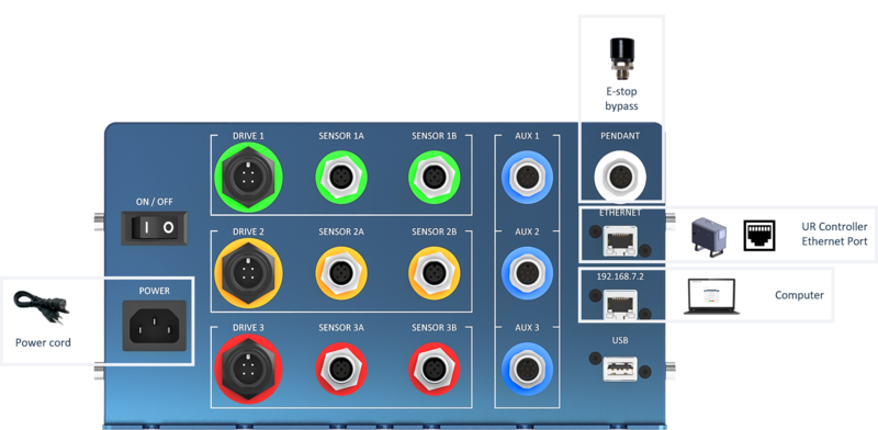
The MachineMotion controller has several connectors. Each connector is meant for use with certain device types. Use the following tables and images (Figures 6a and 6b) to connect your system. Add jumpers to all unused SENSOR, PENDANT and SAFETY IN connectors.
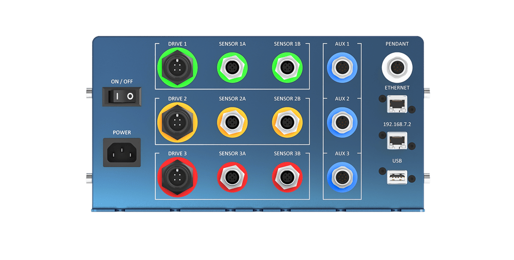
Table 1: MachineMotion front panel components & connectors
| Device(s) | Vention Part Number | MachineMotion Connector |
|---|---|---|
| Stepper Motors | MO-SM-00X-0001 | DRIVE 1, DRIVE 2, DRIVE 3 |
| End-of-Travel Sensors | CE-SN-004-0001 | SENSOR 1A/B, SENSOR 2A/B, SENSOR 3A/B |
| Encoder | CE-SN-002-0001 | AUX 1, AUX 2, AUX 3 |
| Digital IO Module | CE-MD-001-0001 | AUX 1, AUX 2, AUX 3 |
| Power-off Brake | MO-PT-002-0001 | AUX 1, AUX 2, AUX 3 |
| Jumper | N/A Included with MachineMotion |
PENDANT |
| UR Controller (Static Address Method) | N/A | ETHERNET |
| Computer UR Controller (DHCP Method) | N/A | 192.168.7.2 |
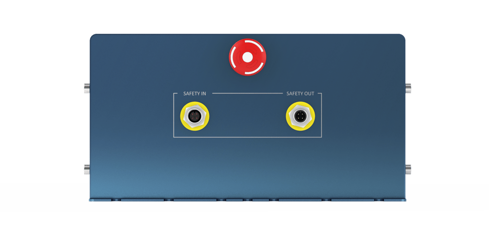
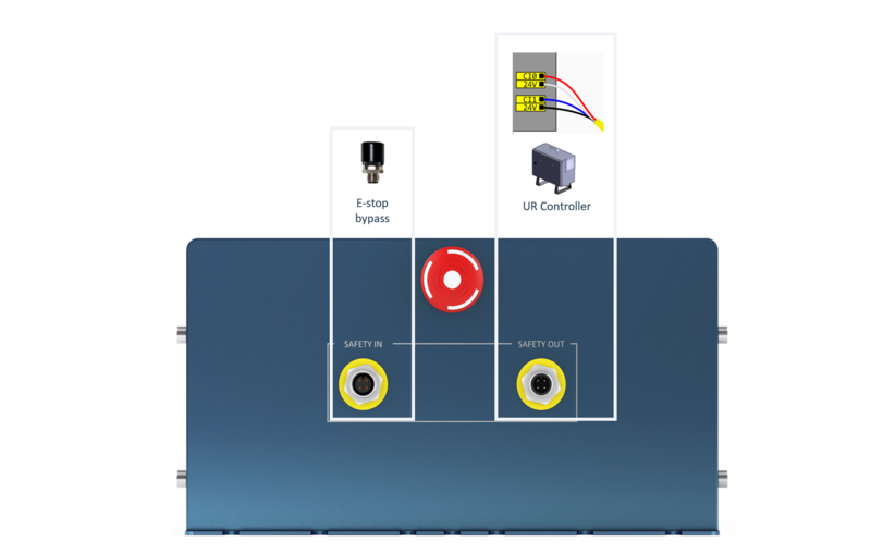
Table 2: MachineMotion back panel components & connectors
| Device | Description | MachineMotion Connector |
|---|---|---|
| Safety Input | Input used to place the system in emergency stop mode (redundant dry contacts) | SAFETY IN |
| Safety Output | Output used to trigger the system inputs of other devices (redundant dry contacts) | SAFETY OUT |
The safety input and output allow MachineMotion to participate in a unified safety solution where the UR Controller is the safety parent or the UR and MachineMotion controllers are configured in a safety loop.
With the UR Controller configured as the safety parent, pressing the UR E-stop button triggers an emergency stop at the MachineMotion controller. When configured in a safety loop, triggering either E-stop will cause both the UR and MachineMotion E-stops to be triggered.
We recommend configuring MachineMotion as a safety child when used in Vention robot cell applications. See our guide on Universal Robots Safety Configuration with MachineMotion for more details.
2.1 Connecting the UR and MachineMotion controllers
This section discusses common MachineMotion connections for pairing with a Universal Robot controller. In the configuration shown in Figure 7, the UR Controller is the safety parent controller (refer to the Universal Robots Safety Configuration for MachineMotion guide for more information). These connections (Figure 7) require the following cables (provided with the MachineMotion package):
- One (1) AC power cord
- Two (2) Jumper connectors (for the PENDANT and SAFETY IN connectors)
- One (1) Ethernet cable (controller communication)
- One (1) Safety E-stop cable
Important: Make sure to add jumpers to the PENDANT and SAFETY IN connectors if you are not using these connectors.
AC power connection
Use the provided AC power cord to connect the MachineMotion controller to an outlet that provides 110V (of AC power) at 15 amps. An average of 400 watts per actuator must be available to properly power the equipment.
MachineMotion IP Addresses
The MachineMotion controller has two different network interfaces: ETHERNET and 192.168.7.2. These two interfaces are distinct, and consequently can be configured differently. They also have different IP addresses. The table below highlights the differences between the two interfaces.
Table 3: Network adapter details
| Physical Connector | IP Address | Configurable | Default Gateway |
|---|---|---|---|
| ETHERNET | 192.168.0.2 (default) | Yes | 192.168.0.1 |
| 192.168.7.2 | 192.168.7.2 | No | 192.168.7.1 |
MachineMotion IP Ports
The MachineMotion controller serves multiple ports, as detailed below.
Table 4: MachineMotion server’s IP ports
| Service Ports | Applications |
|---|---|
| 80 | MachineMotion UX/UI |
| 8888 | Communication setup and basic MachineApps |
| 9999 | Communication with UR controller |
UR and MachineMotion ethernet
The UR and MachineMotion controllers communicate using TCP/IP sockets on standard ethernet. We recommend using a point-to-point connection by running an ethernet cable between the MachineMotion and the UR controller. The UR controller has an ethernet connector available on its bottom panel, and the MachineMotion controller has one on its front panel (labelled ETHERNET). This direct connection requires that the IP address be statically configured. See Static Address Method in Setup the Network below for more details.
For a simplified networking set-up, you can also use the DHCP Method where the IP address is assigned automatically. To do this, you can use an ethernet cable to connect the UR controller ethernet connector located on its bottom panel to the 192.168.7.2 connector of the MachineMotion controller. This provides a faster way to configure your system and start testing. (see Connecting the UR and MachineMotion via Ethernet for more).
Connecting the MachineMotion controller to a computer
To access the MachineMotion control center, you will need to connect your MachineMotion controller from its 192.168.7.2. connector to a computer using an ethernet-to-ethernet or ethernet-to-usb cable.
Jumpers
A jumper must be connected to the PENDANT connector when using the MachineMotion with the UR Controller (see Figure 7). Moreover, use a seoncd jumper on the SAFETY IN connector when the UR Controller is configured as the safety parent.
2.2 Connecting the MachineMotion to Actuators
This section explains which parts and connections are needed when connecting Vention actuators to the MachineMotion controller. See the figure and table below for a summary of the parts and connections.
Vention’s MachineLogic for Universal Robots URCap allows you to integrate linear, rotary and pneumatic actuators for your application.
Linear Actuators
Linear actuators are available from Vention for a variety of uses including range extenders. Vention actuators are connected to the MachineMotion controller using a motor drive and two end-of-travel sensors.
Conveyor Systems
Conveyor systems are available from Vention for building automated belt and gravity roller conveyors. Conveyors connect to the MachineMotion using a motor drive.
A through-beam sensor (CE-SN-006-0001) is typically used to stop or move the conveyor when an object is detected in front of the sensor. Connect the through-beam sensor to the MachineMotion controller with the end sensor connector.
Rotary Actuators
Vention’s rotary actuator allows for application like inspection jigs and soldering stations. The rotary actuator is controlled in terms of angle (degrees) and is connected to the MachineMotion controller as a full actuator using a motor drive and two end-of-travel sensors.
The end-of-travel sensors are used to determine the rotation origin (0 degrees). The end-of-rotation sensors are used to constrain rotational applications (0–360 degrees). End-of-travel sensors are not required for free-form relative rotary applications. See Figure 8 for the MachineMotion controller connectors.
Pneumatic Actuators
Vention’s pneumatic actuators may be controlled from the UR teach pendant, which allows for application like clamping and guidance systems. The pneumatic ecosystem connects to the MachineMotion controller using the Digital IO Module. See the Pneumatic Ecosystem guide for more details.
Note: Depending on the motor rotation and desired home position, the SENSOR 1A and 1B connections shown in Figure 8 may need to be swapped.
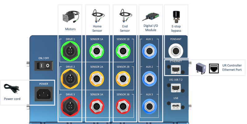
Table 5: MachineMotion controller connections for actuators and conveyors
| Device Type | Uses in robot cells | MachineMotion Controller Connections |
|---|---|---|
| Linear actuators MO-LM-02X-0XXX MO-LM-16-0XXX MO-LM-0003-0XXX MO-LM-019-0001 |
Range extenders |
|
| Conveyors MO-CV-00X-0XXX MO-CV-001-0585 |
Belt and roller conveyor systems |
|
| Rotary actuator MO-RM-002-0001 |
Inspection station, soldering & welding jigs |
|
| Pneumatic actuator CA-CY-001-0100 |
Clamping & guidance systems |
|
Once the MachineMotion controller is connected to the UR controller and your Vention components, you can proceed to network configuration. Configuring the network enables communication between the MachineMotion controller and UR controller.
3. Set up the Network
There are two ways to setup your network: the DHCP method and the Static Address method. The following sections describe both.
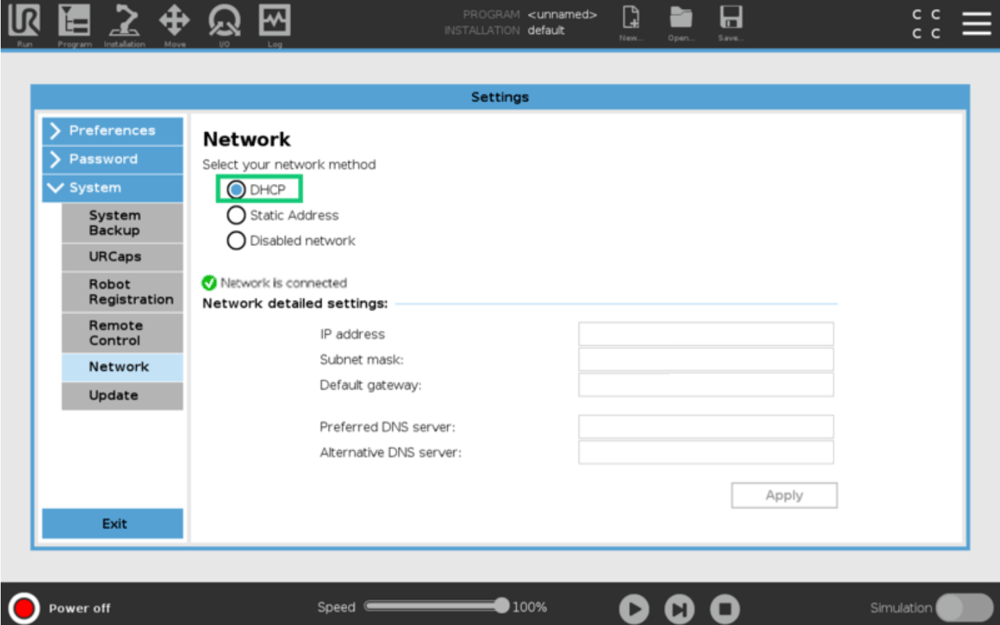
3.1 DHCP Method
The simplest way to configure communications between the UR controller and the MachineMotion controller is to use the DHCP method. With the DHCP approach, there is no configuration to be done on the MachineMotion controller. However, this networking method does not support multiple MachineMotion controllers connected to a UR controller.
Make sure that the MachineMotion controller is connected to the UR controller with an ethernet cable at the 192.168.7.2 connector on the MachineMotion controller and the ethernet connector on the bottom panel of the UR controller. If you need to access the MachineMotion Control Center, you will need to disconnect the UR controller from the MachineMotion controller.
On the UR teach pendant home screen, select Menu > Settings > System > Network. Select DHCP as your network method (see Figure 10).
Once you see the ‘Network is Connected’ status on the screen (Figure 10), you can continue your configuration by jumping to the section Configure your System.
Important: To use the DHCP approach make sure your ethernet cable is connected to the 192.168.7.2 connector (on the MachineMotion controller) NOT to the ETHERNET connector.
3.2 Static Address Method
Communication between the UR controller and MachineMotion uses a peer-to-peer ethernet configuration. In order for the ethernet communication to function, both devices must be properly configured. In this system, the UR controller is the controlling entity. It runs the application-level program and sends commands and queries to the MachineMotion controller.
Configuring the MachineMotion Network
- Connect MachineMotion to a 120 V power source via the power cable and POWER connector.
- Connect a computer that has Google Chrome installed to MachineMotion using the provided ethernet cable to the connector labelled 192.168.7.2. If using a computer that does not have an ethernet connector an ethernet-to-usb cable can be utilized.
- Turn on the MachineMotion system using the rocker switch.
- Wait at least 90 seconds for the system to complete its booting sequence.
- Using the Google Chrome browser on your computer, navigate to: 192.168.7.2
The MachineMotion Control Center main menu (see Figure 11) will be displayed.
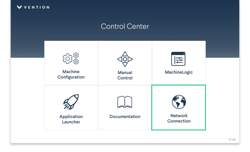
- From the main menu, select Network Connection
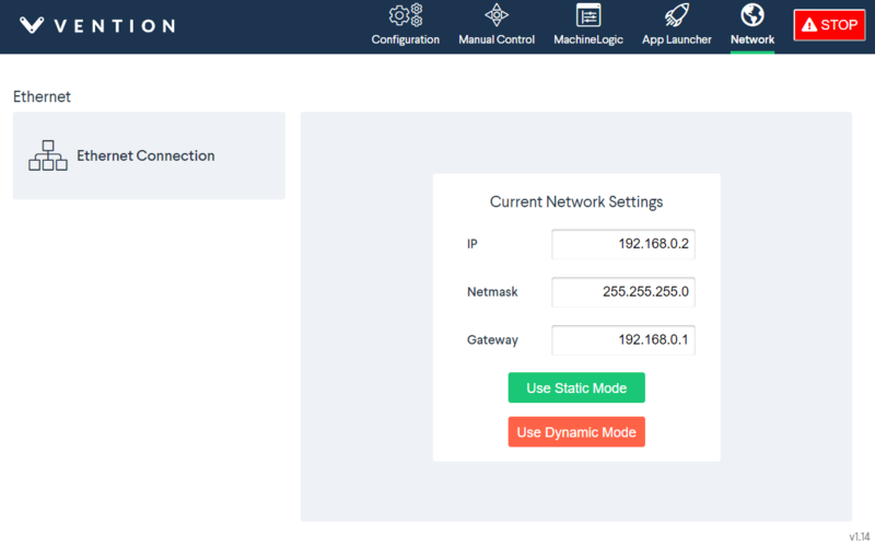
- Modify the IP address of the MachineMotion controller, if desired. The default network configuration for the MachineMotion controller connected to a UR controller is as follows:
- IP address: 192.168.0.2
- Netmask: 255.255.255.0
- Gateway: 192.168.0.1
- If you have modified any of the fields or want to keep the default configuration, select Use Static Mode to save.
Configuring the UR Controller Network
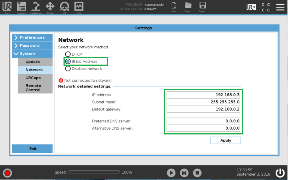
On the UR teach pendant home screen, select Menu > Settings > System > Network (see Figure 13).
Enter the parameters as shown in Figure 14. Note that here, the UR controller IP address is 192.168.0.3, and the MachineMotion controller IP address is 192.168.0.2. Any address in the 192.168.0.xxx subnetwork is acceptable. The other parameters should be configured as shown in Figure 14. Click Apply to save your settings.
The network status line should display Network is connected after a few seconds. If it does, the network setup is complete.
4. Configure your system
In order to have the UR controller communicate with the components connected to the MachineMotion controller, you have to configure your Vention components within the Polyscope environment.
On the teach pendant home screen, select Installation > UR Caps > MachineLogic for Universal Robots, to navigate to the Vention system configuration screen
The Vention URCap configuration screen has two main windows:
4.1 Upper Window
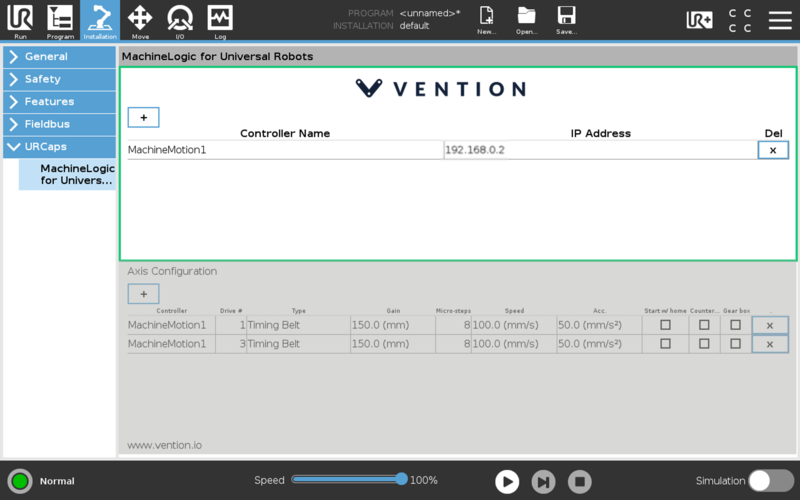
The upper window of the Vention URCap is used to define a MachineMotion controller instance (see Figure 15). Note that multi-controller systems can be created by adding more than one controller. To add a controller, select the + icon.
- Controller Name: Name assigned to the MachineMotion controller
- IP Address: IP address of the MachineMotion controller. In Figure 15, IP address 192.168.0.2 is used for the MachineMotion controller
You can edit the controller name by clicking on the default MachineMotion name and using the keypad to enter the desired name.
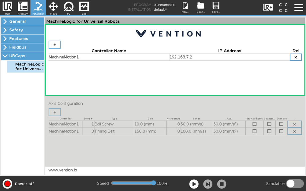
Important: If you are using the DHCP networking approach, you have to overwrite the IP address value with 192.168.7.2 (see Figure 16). To overwrite, click on the IP address field and use the keypad to enter the new IP address.
4.2 Lower Window
The lower window of the Vention URCap defines actuators for linear axes of motion (see Figure 17). For example, the system shown in Figure 17 has two actuators linked to the controller, which is called MachineMotion1. These actuators are plugged into drive connectors one, and three of the controller, hence the (1), (3) appearing under the Drive # setting.
- Controller: Name of the controller on which the actuator is plugged
- Drive Index: Indicates which connector the actuator is connected to on the MachineMotion controller
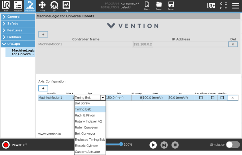
- Type: Indicates the type of actuator. Setting the type will populate the Gain, Micro-stepping, Speed, and Acceleration fields with default values, but you can still edit them if you wish to
- Gain: Mechanical gain of the mechanical system in mm or degrees per motor turn
- Micro-stepping: These settings must match the micro-stepping setup of the drives inside the MachineMotion controller (8 is the default)
- Speed: Default actuator displacement speed in mm/s, if none is specified in the program
- Acceleration: Default actuator displacement acceleration in mm/s2, if none is specified in the program
- Start with home: Indicates whether the MachineMotion should perform a homing sequence before the start of each program
- Counterclockwise: Select this to reverse the direction of motor rotation for the axis
- Gear box: Select this if you are using a 5:1 gear box so the system can automatically adjust your gain
After configuring the installation in both windows, click Save at the top of the screen to complete.
5. Use MachineLogic for Universal Robots
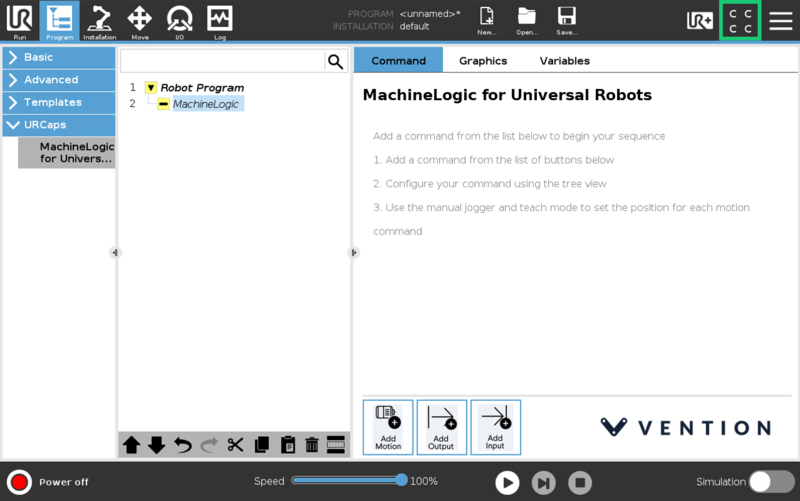
5.1 Program Screen
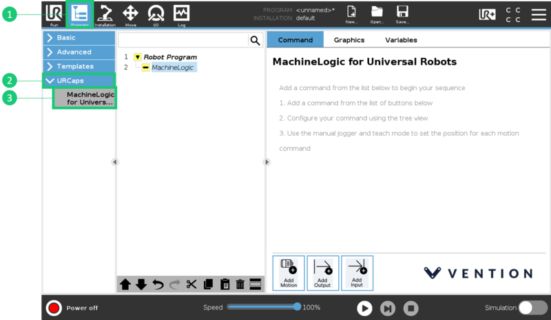
Navigate to the program screen to create a robot program in the URCap.
- Start by clicking the Program icon on the right-hand side of the top toolbar.
- Then opening the URCaps drop-down,
- And choosing the MachineLogic for Universal Robots URCap
The three steps are outlined in Figure 18 below:
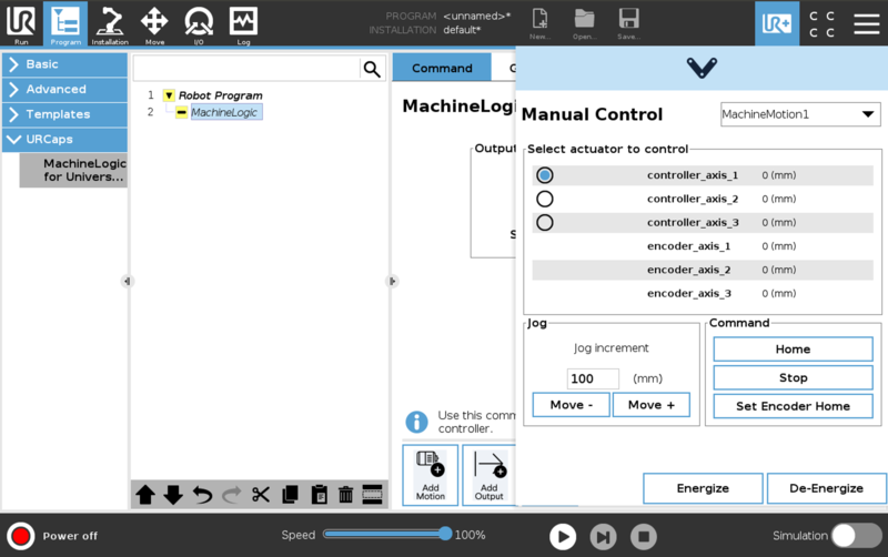
5.2 Manual Control
To manually control your actuators from the UR Teach Pendant you will need to use the Jogger feature of the URCap.
Open the Jogger by clicking on the UR+ screen located right-hand side of the top toolbar (See Figures 19a & 19b).
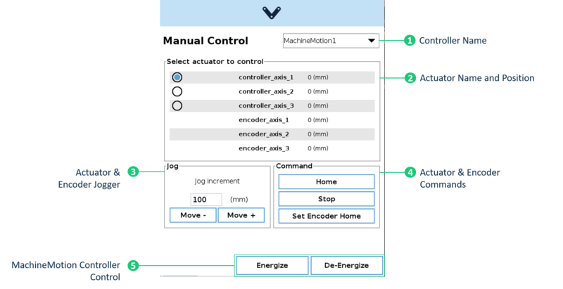
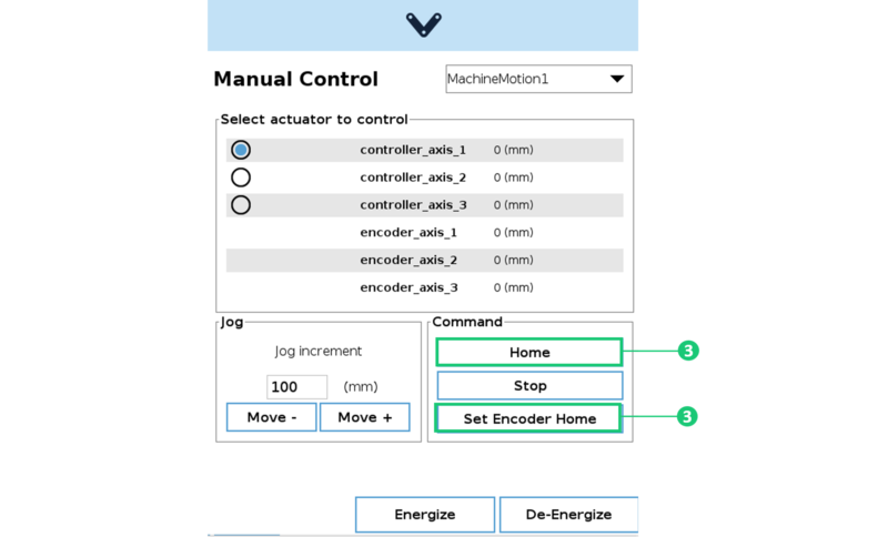
The input fields in the Jogger screen (as labelled in Figure 20) are explained below:
- Controller Name: Choose the MachineMotion controller to which your actuator(s) is connected.
- Actuator Name and Position: In the list of controllers, you can select the actuator you want to manually control.
- Actuator & Encoder Jogger: To jog the actuator and encoder to a new position, change the jog increment to the desired value and press Move + and Move - buttons to execute a move relative in the selected direction.
- Encoder commands: In the command area, you can ‘Home’ the selected or ‘Stop’ all motion on all actuators. You can also set a new position as the encoder’s zero by pressing ‘Set Encoder Home’.
- MachineMotion controller control: Energize and De-Energize the MachineMotion Controller directly from the pendant.
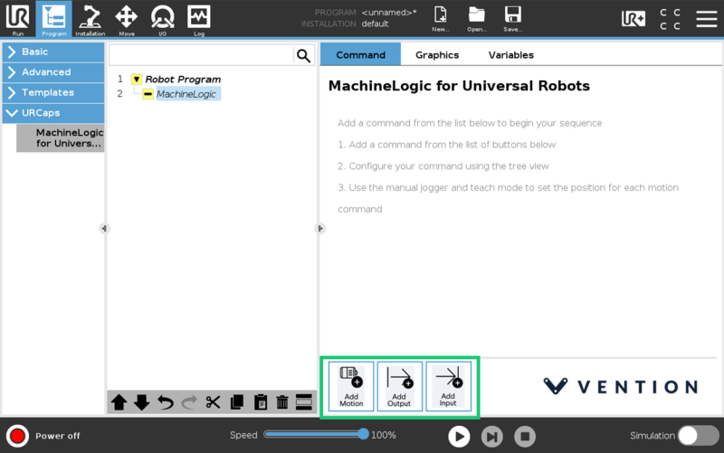
5.3 Command Screen
MachineLogic for UR contains 3 primary commands, which can be added to your robot program through the teach pendant screen.
In the Command tab of the program window, you will see the basic instructions for building your sequence. Build your sequence by choosing one of the 3 commands located at the bottom of the program window (Figure 21): Add Motion, Add Output, Add Input.
5.3.1 Add Motion
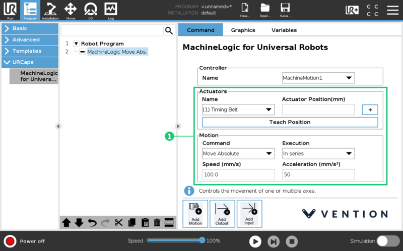
The Add Motion command is for building sequences that will move your equipment. Typically, the required fields are:
- Controller: The name of the MachineMotion controller to execute the motion command. This field is mandatory for all motion commands.
- Actuator Name: The name of the actuator to be set in motion. Note that you can add and control multiple actuators in one command by clicking the ‘+’ symbol.
- Actuator Position: The end position of the actuator in [mm] for linear actuators or [degrees] for rotary actuators.
- Command: This refers to the type of motion and the options include Move to Position, Move Relative, Move Relative Combined, Move to Position Combined, Move to Closest Angle and Push (for pneumatic actuators).
- Execution: Used to specify if the command is executed in series or in parallel with other commands.
- Speed: This refers to the desired speed, in [mm/s] or [deg/s], of the actuator during the move.
- Acceleration: This refers to the desired acceleration, in [mm/s2] or [deg/s2], of the actuator during the move.
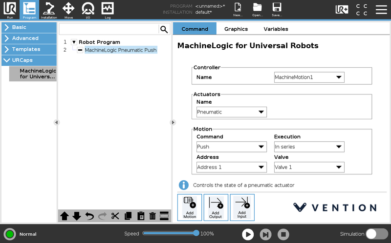
- Address: This is a field specific to pneumatic actuators. It refers to the pre-installed address on the I/O expander that connects the actuator to the MachineMotion controller.
The following is a summary table of all Add Motion commands, their required fields, functions and the expected inputs:
Table 6: Add Motion Command Inputs by Actuator Type
| Actuator Type | Actuator Inputs | Motion Command | Motion Inputs |
|---|---|---|---|
| Timing Belt Ball Screw Rack and Pinion Electric Cylinder |
Actuator Position [mm] | Home Move to Position Move to Position Combined Move Relative Move Relative Combined |
Execution Speed [mm/s] Acceleration [mm/s2] |
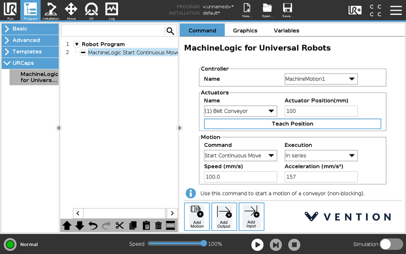
| Rotary Indexer | Actuator Position [deg] | Home Move to Position Move to Position Combined Move Relative Move Relative Combined Move to Closest Angle Start Continuous Move Stop Continuous Move |
|
| Belt Conveyor Roller Conveyor |
Actuator Position [mm] | Move Relative Start Continuous Move Stop Continuous Move |
Execution Speed [mm/s] Acceleration [mm/s2] |
| Pneumatic | N/A | Push Pull Idle |
Execution Address Valve |
| Custom Actuator | Actuator Position [mm] | Home Move to Position Move to Position Combined Move Relative Move Relative Combined Move to Closest Angle Start Continuous Move Stop Continuous Move |
Execution Speed [mm/s] Acceleration [mm/s2] |
5.3.2 Teach Position
The Teach Position feature is useful for programming quick and precise motion commands. The feature allows you to ‘teach’ the program your desired final position by physically moving your actuator.
There are 6 steps to using Teach Position outlined below. If you plan on completing a Move to Position, start by homing in manual control as seen in step 3.
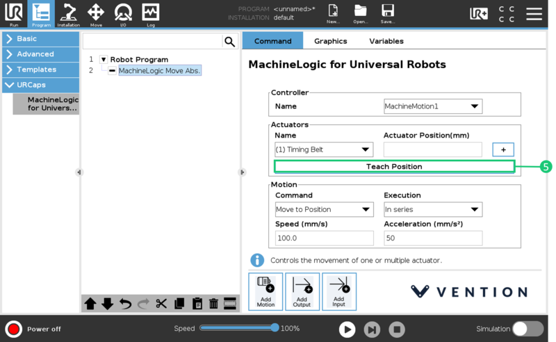
- Set up your motion command with the actuator name, motion command type, execution, speed and acceleration values (see Figure 22).
- Open the Jogger menu. Ensure that the correct MachineMotion controller and actuator are selected before proceeding.
- If you are using Move to position, home the encoder by clicking Home, then click Set Encoder Home.
If you are using Relative Move click Set Encoder Home at your starting position. This way, the encoder will start measuring the distance from the starting position (see Figure 23).
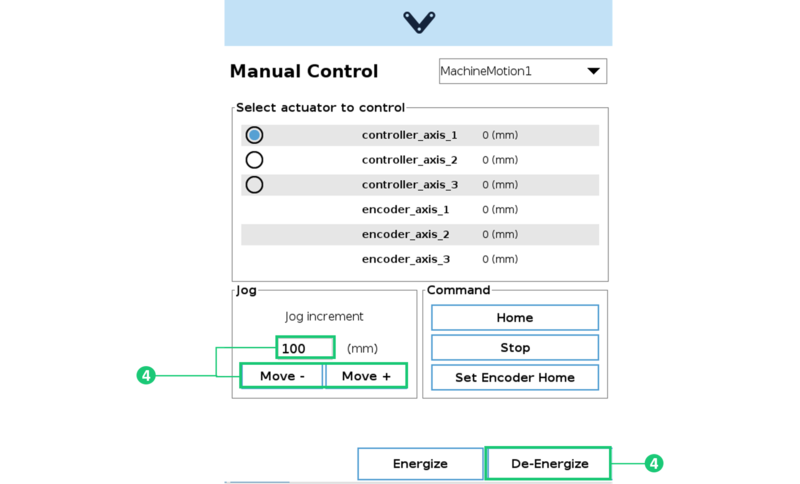
- Then, either enter a value in the Jog input, use the Move + and Move - buttons or press De-energize and physically move the axis to the desired position (see Figure 24).
- Once the axis is in the desired position, click Teach Position in the command screen (Figure 25)
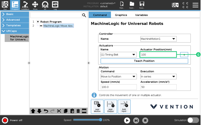
- Wait until the value of the desired position is populated in the Actuator Position before saving the program (see Figure 26).
5.3.3 Add Output
The Add Output commands are used to perform non-motion actions on the MachineMotion Controller and other components connected to the controller. There are 6 output command categories defined below. For each category, the user must specify which MachineMotion Controller should receive the command.
- MachineMotion ON/OFF: When set to OFF, this command de-energizes all actuators connected to a MachineMotion Controller. Set the field to ON to restore actuators connected to a controller and reset the software E-stop.
- Set Position: This command overrides the current position of an actuator or an encoder with the specified value.
- Set Angle: Use this command to override the angle at which a rotary indexer is set.
- Safety Reset: This command releases the MachineMotion system from a manual e-stop.
- Digital I/O Module Outputs: Use this command to change the state of a digital output.
Table 7: Add Output Command Input Fields by Category
| Category | Input Fields |
|---|---|
| MachineMotion Actuator ON/OFF | Select State: ON, OFF |
| Set Position | Actuator Position [mm] Encoder Position [mm] |
| Set Angle | Actuator Angle [deg] |
| Safety Reset | None Note: Before executing this command, you must release the physical E-stop button on the MachineMotion controller. |
| Digital I/O Module Outputs | Address (on the I/O expander) Output State: 1(ON), 0(OFF) |
5.3.4 Add Input
The Add Input commands are used for receiving and storing status data from the MachineMotion controller and components connected to the controller. There are 5 input command categories defined below. For each category, the user must specify from which MachineMotion controller the input is received and in which variable the data should be stored. The variables can be used in your robot program.
- MachineMotion Status: Use this to check if the MachineMotion controller is processing a command.
- MachineMotion Safety Status: To receive and save the E-stop status of the MachineMotion controller.
- Get Position: Used to receive and save the current position of an actuator or encoder.
- Digital Inputs: To read and save the state of a digital input.
- Pneumatic Inputs: To read and save the state of a pneumatic input.
Table 8: Add Input Command Input Fields by Category
| Category | Input Fields |
|---|---|
| MachineMotion Status | Select Variable: ‘busy’ or ‘available’ |
| MachineMotion Safety Status | Select Variable: ‘estop/status false’ or ‘estop/status true’ |
| Get Position | Select Input - the actuator whose position will be stored Select Variable Input Type: float Input Variable: distance in mm |
| Digital Inputs | Address - on the I/O expander Select Input - the digital input whose state will be stored Select Variable Input Type: string Input Variable: ‘24V’ or ‘0V’ |
Using the Input Fields
Use the icons highlighted here (Figure 27) to:
- Add new variables to the list of variables
- Edit the selected variables
- Delete the selected variable
![]()