Universal Robots Safety Configuration with MachineMotion
Overview
This guide describes the safety configurations of Universal Robots with the MachineMotion V2 controller.
The goal of the safety system is to power off all actuators upon an E-stop event.
This guide provides instructions for Universal Robots Safety Configuration with MachineMotion V2. For details on Universal Robots Safety Configuration with MachineMotion V1, refer to the ‘Documentation for Previous Product Versions’ section at the bottom of this page.
MachineMotion Safety IO
Three main components dictate the safety configuration of the MachineMotion V2 controller: The E-stop button, the SAFETY IN and the SAFETY OUT ports. These components are illustrated in the figure below.
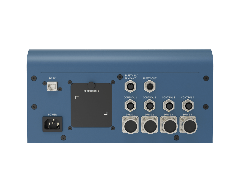
The following table describes the functionality of each component
| MachineMotion V2 Port | Description |
|---|---|
| SAFETY IN/PENDANT | Used to connect other safety devices that can place MachineMotion V2 in an emergency stop mode (This input should be fed by redundant dry contacts) |
| SAFETY OUT | Used to trigger and place other devices in an emergency stop mode (redundant dry contacts, normally closed) |
| E-STOP | When pressed, the E-stop button places the system in emergency stop mode. Needs to be released to disengage the emergency stop mode. |
Status LED
Located on the top of the MachineMotion controller, there is a status LED to display the state of the controller.
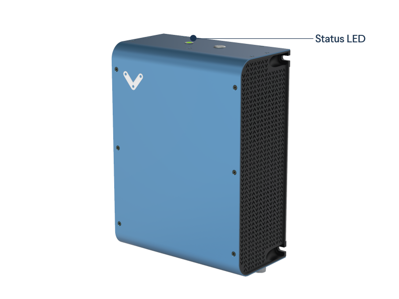
To understand the status LED, please see table below:
 |
MachineMotion controller is booting up |
 |
MachineMotion controller is ready to operate (e-stop inactive) |
 |
MachineMotion is running a script |
 |
MachineMotion controller is not ready to run: It is in an emergency stop state. This means that the physical e-stop on the MachineMotion controller is triggered or the software stop is on. |
Universal Robots and MachineMotion V2 Safety Configuration
Universal Robots Safety Interfacing
This section will cover the safety wiring of Universal Robots and Vention MachineMotion V2 controller.
- Refer to the Robot Safety module user manual here for a wiring diagram.
- Configure UR’s Safety Input & Output Pins
The input & output pins on the Universal Robots controller can be configured as safety pins using the UR Teach Pendant.
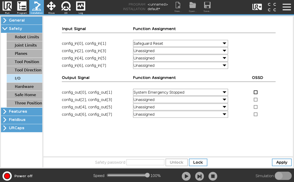
Navigate to Installation > Safety > I/O to configure the safety pins
Set config_out[0], config_out[1] to “System Emergency Stop”, as seen in the figure below
Notes:
- CO0 and CO1 are configured as System Emergency Stop.
- CI0 and CI1 are configured as Safeguard Reset.
Resetting MachineMotion V2 after an Power Cycle / E-stop
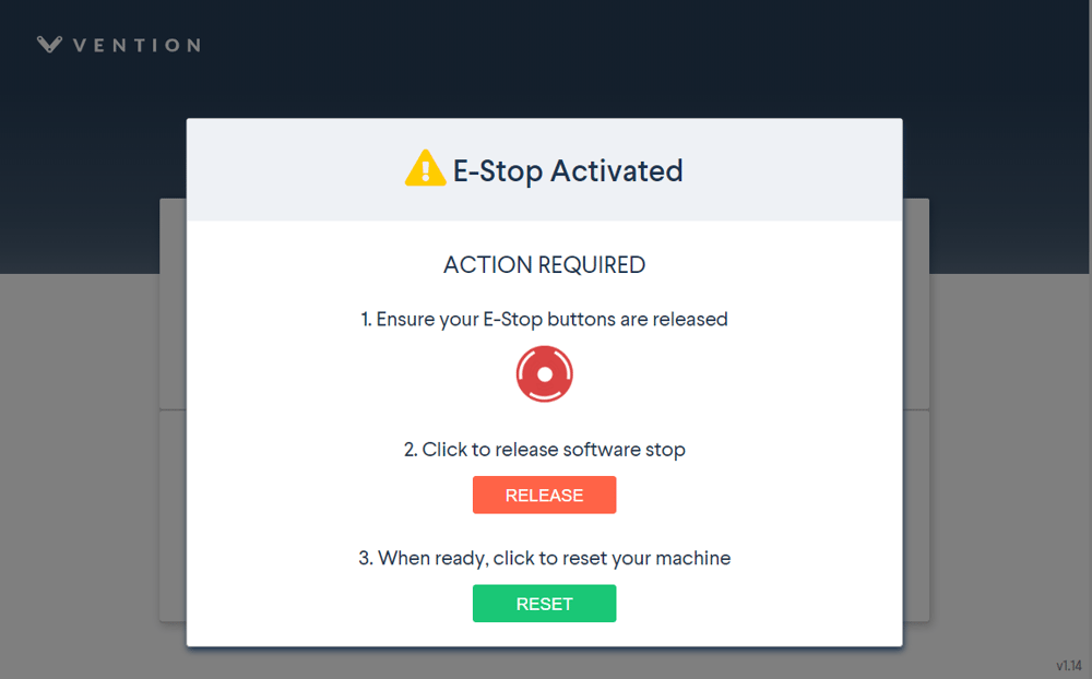
After a power cycle or E-stop, you will need to release the software E-stop on the MachineMotion V2. This requires you to interact with E-stop pop-up on the MachineMotion V2 Control Center, as seen in the figure below.
It is a 2-step process, involving releasing all the safety inputs, as well as a user confirmation to restart the system.
Refer to sections 5.3.3 (Add Output) & 5.3.4 (Add Input) in the MachineLogic for Universal Robots tech doc here
The Add Output commands are used to perform non-motion actions on the MachineMotion V2 Controller and other components connected to the controller. For each category, the user must specify which MachineMotion V2 Controller should receive the command.
- MachineMotion ON/OFF: When set to OFF, this command de-energizes all actuators connected to a MachineMotion Controller. Set the field to ON to restore actuators connected to a controller and reset the software E-stop.
- Safety Reset: This command releases the MachineMotion system from a manual e-stop.
| Category | Input Fields |
|---|---|
| MachineMotion Actuator ON/OFF | Select State: ON, OFF |
| Safety Reset | None Note: Before executing this command, you must release the physical E-stop button on the MachineMotion controller. |
The Add Input commands are used for receiving and storing status data from the MachineMotion controller and components connected to the controller. There are 5 input command categories defined below. For each category, the user must specify from which MachineMotion controller the input is received and in which variable the data should be stored. The variables can be used in your robot program.
- MachineMotion Safety Status: To receive and save the E-stop status of the MachineMotion controller.
| Category | Input Fields |
|---|---|
| MachineMotion Safety Status | Select Variable: ‘estop/status false’ or ‘estop/status true’ |