

User manual
Updated: Wednesday, March 27th 2024
Robot Safety Module User Manual
Contents
Overview
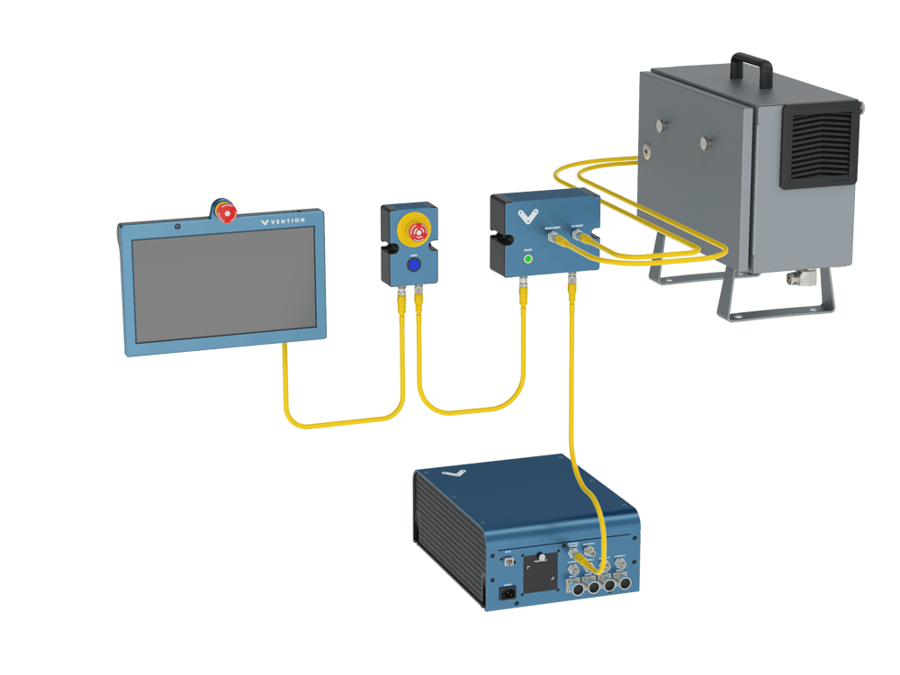
The Robot Safety Module is the interface between Vention’s MachineMotion 2 controller & Vention’s partner robots’ safety interfaces. The Robot Safety Module manages the safety fault events that happen on the machine to safely stop both the MachineMotion 2 controller and the robot. With the Robot Safety Module connected in Vention’s safety chain, a safety event from the robot will stop the MachineMotion 2 controller and a safety event from Vention’s safety chain will also stop the robot. The Robot Safety Module also serves as an Ethernet switch between Vention’s Pendant, MachineMotion 2 controller and the robot.
Features
- Configuration Free, Plug & Play
- Compatible with MachineMotion 2
- Daisy-chainable
- Compatible with multiple Cobot brands
- On-board status LED
- Internal 3 port Ethernet switch
Included in the box
| Part Number | Description | Quantity |
|---|---|---|
| CE-SA-009-0000 | Robot Safety Module | 1 |
| CE-SA-111-0001 | Robot Safety Module “TO ROBOT” Cable | 1 |
| CE-SA-112-0001 | Robot Safety Module “FROM ROBOT” Cable | 1 |
| CE-CA-102-5001 | MachineMotion 2 Safety Extension Cable - 5m | 1 |
| CE-SA-102-0001 | MM2 Safety Jumpers | 1 |
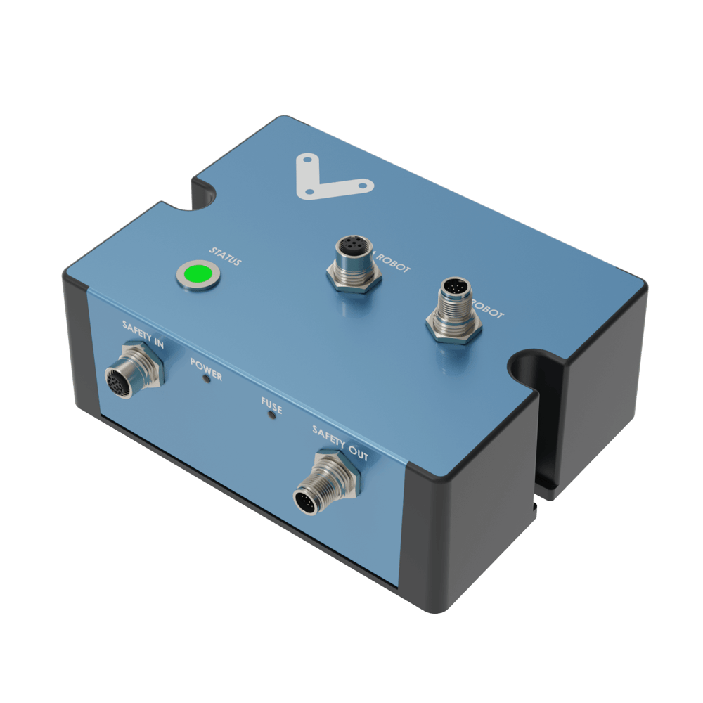
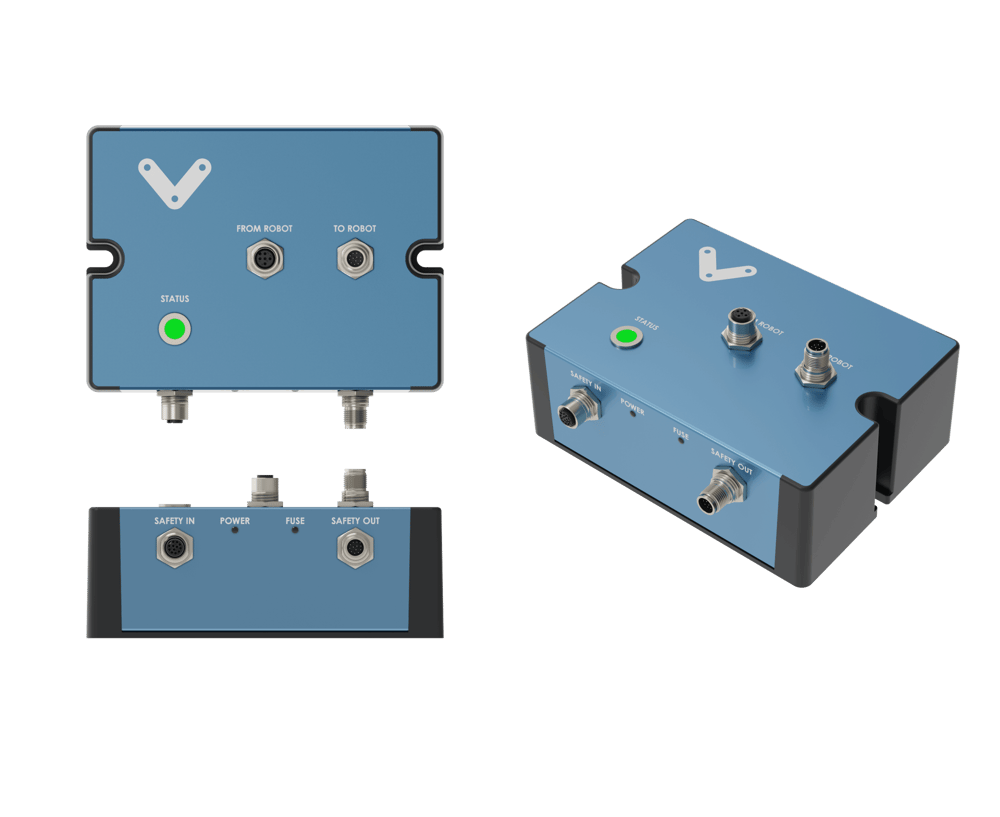
Physical Interface
Important Notes

The Robot Safety Module performs safety functions as a part of a whole installation or machine. A complete safety system normally includes sensors or input units, logic units and contactors or output units. The installer of the installation or machine is responsible for ensuring proper functioning of the whole system. The total concept of the control system into which the Robot Safety Module is integrated must be validated by the user. Vention cannot guarantee all specifications of an installation or a machine without being responsible for the risk assessment and the design of the safety system.
Vention takes over no liability for recommendations which are given or implied in this manual.
Included Cables
The Robot Safety Module comes with multiple cables. It is important to use the appropriate cable, properly connected for the intended application. The included cables are:
- Robot Safety Module “TO ROBOT” Cable (CE-SA-111-0001): intended to connect the Robot Safety Module safety output signals (Safety, Reset and Ethernet) to the robot controller.
- Robot Safety Module “FROM ROBOT” Cable (CE-SA-112-0001): intended to connect the robot safety output signals from the robot controller to the Robot Safety Module.
- MachineMotion 2 Safety Extension Cable – 5m (CE-CA-102-5001): intended to connect the Robot Safety Module to Machine Motion V2 or to another Vention’s safety device (in case multiple safety devices/modules are daisy-chained).
FROM ROBOT Port
This port connects to the robot controller using the Robot Safety Module “FROM ROBOT” Cable (CE-SA-112-0001). It connects the redundant 24V safety outputs of the robot to the Robot Safety Module (more information on the pinout can be found in the datasheet).
TO ROBOT Port
This port connects to the robot controller using the Robot Safety Module “TO ROBOT” Cable (CE-SA-111-0001). It connects the redundant dry output contacts, the robot RESET and Ethernet signals from the Robot Safety Module to the robot controller (more information on the pinout can be found in the datasheet).
SAFETY IN Port
This port connects to another Vention safety device/module SAFETY OUT port using the MachineMotion 2 Safety Extension Cable – 5m (CE-CA-102-5001). Multiple Vention safety devices can be daisy-chained through this port:
- Another Robot Safety Module (CE-SA-009-0000)
- E-Stop and Reset Module 2 (CE-SA-007-0000)
- Safety Module (CE-SA-008-0000__2)
- MachineMotion 2 Pendant (CE-TP-004-0001)
If this port is not used, the included yellow jumper must be inserted. More information on the pinout can be found in the datasheet.
SAFETY OUT Port
This port connects to a MachineMotion V2 or another Vention safety device/module SAFETY IN port using the MachineMotion 2 Safety Extension Cable – 5m (CE-CA-102-5001). This port also provides the 24V supply to the Robot Safety Module.
More information on the pinout can be found in the datasheet.
POWER and FUSE LEDs
The Robot Safety Module is 24V powered through the SAFETY OUT port. When powered, the white POWER LED will light up.
If 24V and 0V are accidently shorted, the red FUSE LED will light up indicating a short fault. The LED will turn OFF when the short fault is removed.
STATUS LED
This LED lights green when no safety fault event is detected neither from the SAFETY IN port nor from the FROM ROBOT port. It will light red if a safety fault event is detected from the SAFETY IN port and/or from the FROM ROBOT port.
| Status LED Color | Description |
|---|---|
| Green | Normal operation: no safety fault is detected |
| Red | Fault mode: one or more safety faults are detected |
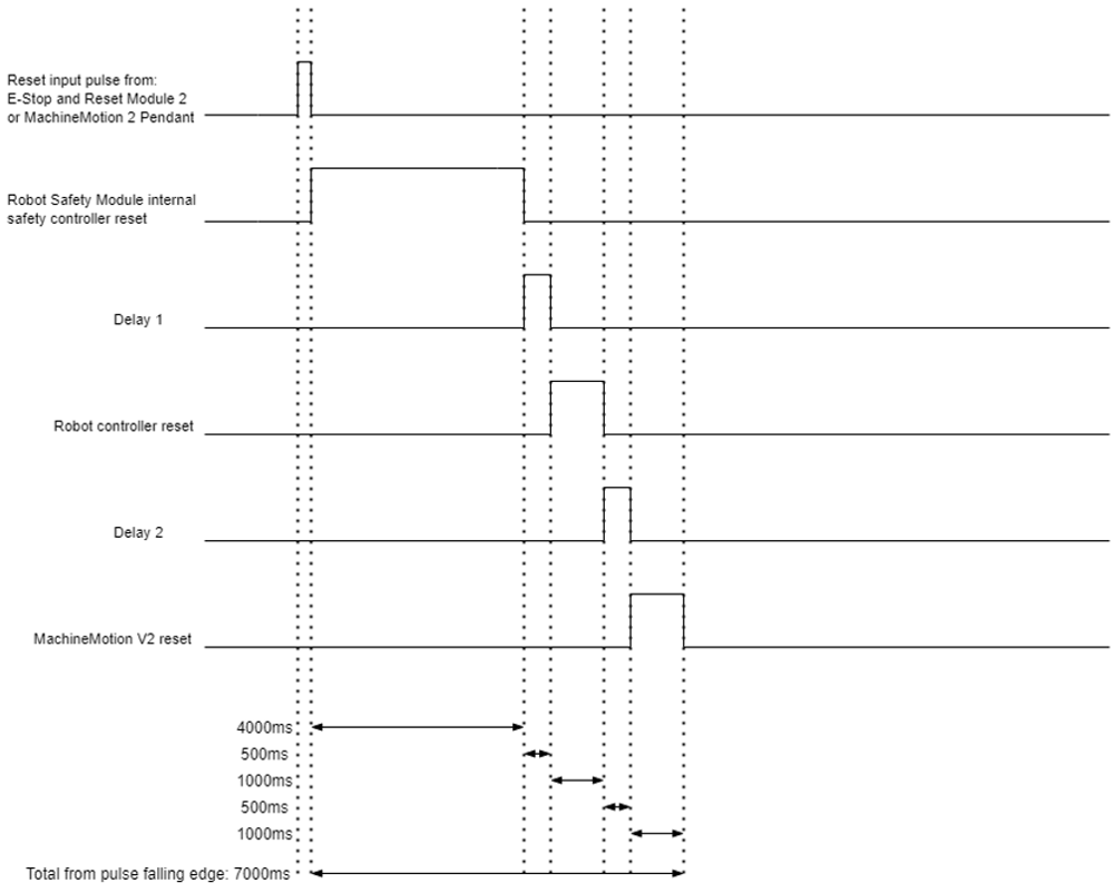
RESET
The Robot Safety Module has internal circuitry to divide a single Reset input pulse from:
- Reset button press on an E-Stop and Reset Module 2 (CE-SA-007-0000) connected in the SAFETY IN loop of the Robot Safety Module
- Software RESET on the MachineMotion 2 Pendant (CE-TP-004-0001) connected in the SAFETY IN loop of the Robot Safety Module
to 3x RESET outputs with specific delays to the following:
- Reset the internal safety controller of the Robot Safety Module. This action will take 4 seconds to complete
- Reset the robot controller through the RESET dry contacts on the “TO ROBOT“ connector (pin 7 and pin 8). This action will take 1 second.
- Reset the MachineMotion V2 controller through the RESET dry contacts on the “SAFETY OUT“ connector (pin 7 and pin 8). This action will take 1 second.
**Note: **There is a 0.5 delay between each reset. The total time it will take for the whole system to reset (internal safety controller, robot controller and MachineMotion V2 controller) is 7 seconds.
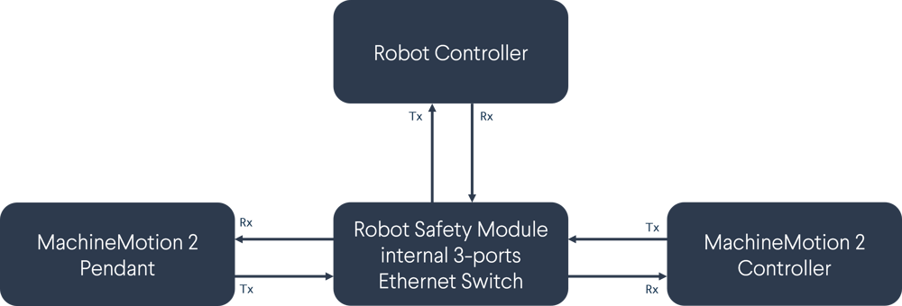
Ethernet 3-ports Switch
The Robot Safety Module has a 3 ports 10/100MB Ethernet switch to connect the MachineMotion 2 Pendant, the robot controller and the MachineMotion V2 into a muti-device Ethernet Network. The following diagram summarizes this connection:
Safety

Functional error !Danger to life, risk of serious injuries or property damage
- The Robot Safety Module may only be connected to the equipment listed in this manual.
- The Robot Safety Module is designed to operate in indoor environments without dust or high humidity. Dust and dampness may lead to malfunction. Do not install or operate the Robot Safety Module outdoors.
Information
- The Robot Safety Module shall not be put into operation only after the safety functions have been tested during the commissioning.
- The use of the Robot Safety Module does not prevent the automatic reset of a robot connected to the TO ROBOT port.
- The use of the Robot Safety Module does not prevent the automatic start of the devices connected to the TO ROBOT and SAFETY OUT ports. According to EN IEC 60204-1:2018 and EN ISO 10218-1:2011 it is not allowed to restart automatically after emergency stop. Therefore the control systems of the connected devices have to disable the automatic start after emergency stop.
- Opening the Robot Safety Module or implementing unauthorized changes voids any warranty.
Applications
The Robot Safety Module is intended to link the safety interfaces of Cobots with MachineMotion 2 controller.
Connecting Robot Safety Module
- Connect the Robot Safety Module to the MachineMotion 2 Pendant (CE-TP-004-0001) or any other Vention safety module using the MachineMotion 2 Safety Extension Cable – 5m (CE-CA-102-5001) through the SAFETY IN connector. In case the MachineMotion 2 Pendant or any other Vention safety module are used, the included yellow jumper must be inserted.
- Connect the Robot Safety Module to the MachineMotion V2 Controller using MachineMotion 2 Safety Extension Cable – 5m (CE-CA-102-5001) through the SAFETY OUT connector.
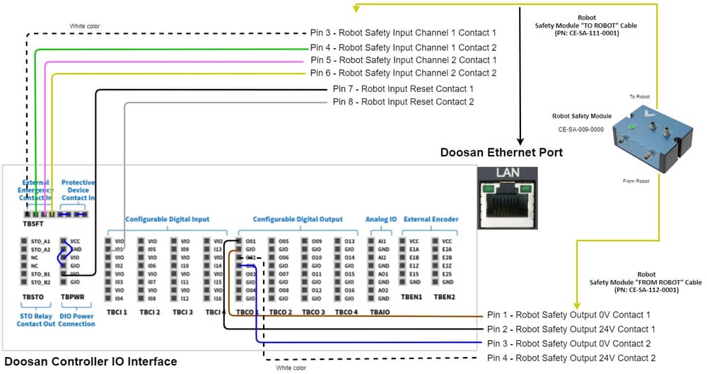
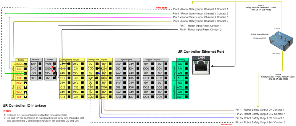
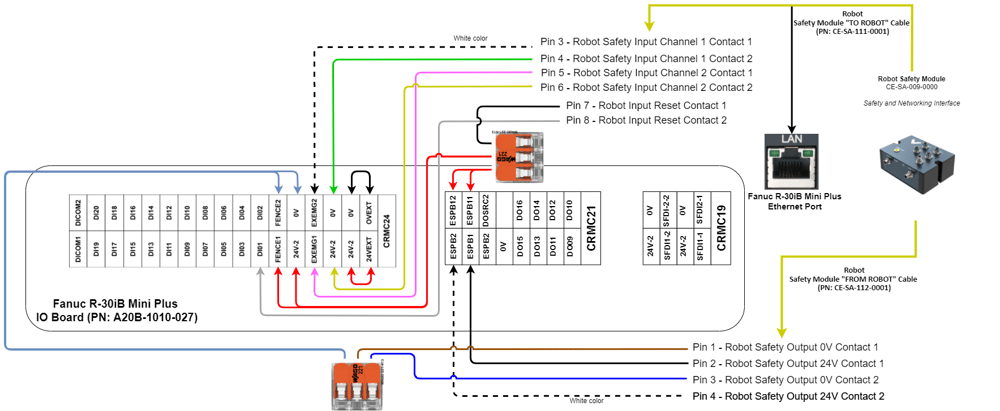
- Connect the Robot Safety Module to the robot controller using the Robot Safety Module “TO ROBOT” Cable (CE-SA-111-0001) through the TO ROBOT connector. The other ends of the cable, connect as follows:
- Robot Safety Input Channel 1 Contact 1 (white wire) connects to the first contact of the emergency stop input in the robot controller
- Robot Safety Input Channel 1 Contact 2 (green wire) connects to the second contact of the emergency stop input in the robot controller
- Robot Safety Input Channel 2 Contact 1 (pink wire) connects to the third contact of the emergency stop input in the robot controller
- Robot Safety Input Channel 2 Contact 2 (yellow wire) connects to the fourth contact of the emergency stop input in the robot controller
- Robot Input Reset Contact 1 (black wire) connects to 24V output in the robot controller
- Robot Input Reset Contact 2 (grey wire) connects to a configurable input in the robot controller. This input should be configured as “Reset” in the robot’s interface
- The RJ45 connector connects to the Ethernet port in the robot controller
- Connect the Robot Safety Module to the robot controller using the Robot Safety Module “FROM ROBOT” Cable (CE-SA-112-0001) through the FROM ROBOT connector. The other end of the cable, connect as follows:
- Robot Safety Output 0V Contact 1 (brown wire) connects to a 0V output in the robot controller
- Robot Safety Output 24V Contact 1 (black wire) connects to a configurable output in the robot controller. This output should be configured as Emergency Stop output in the robot’s interface.
- Robot Safety Output 0V Contact 2 (blue wire) connects to another 0V output in the robot controller
- Robot Safety Output 24V Contact 2 (white wire) connects to a configurable output in the robot controller. This output should be configured as Emergency Stop output in the robot’s interface.
Safety Data
The safety data can be found in the Robot Safety Module datasheet.
EU Declaration of Conformity
The Robot Safety Module is in compliance with the Machinery directive, the RoHS directive and the EMC directive. The EU declaration of conformity is available in the documentation section of the Robot Safety Module product page.