|
Overview
The Robot Safety Module CE-SA-016-0001, is intended to interface with a robot and with the MachineMotion V2. The Safety IN port and the Reduced port are connected to safety modules which change the state of the robot and the MachineMotion. A Robot Safety Module (no MachineMotion) CE-SA-016-0002 is also available when there is a need for a heads up signal to place Cobot in collaborative mode. The Robot Safety Module (no MachineMotion) CE-SA-016-0002 can be used when our Safety Module features are considered for an application (muting, mode-switching or auto-reset).
This datasheet provides technical specifications for Vention’s Robot Safety Module V2. For details on Vention’s Robot Safety Module V1, refer to the ‘Documentation for Previous Product Versions’ section at the bottom of this page.
Features
Compatible with MachineMotion V2
Configuration-free: plug & play
Modules can be daisy-chained
Support robot reduced/collaborative mode
Configurable heads-up delay
Compatible with most robot brands
Five port Ethernet switch (safety IN, safety OUT, reduced, to robot, internal mcu)
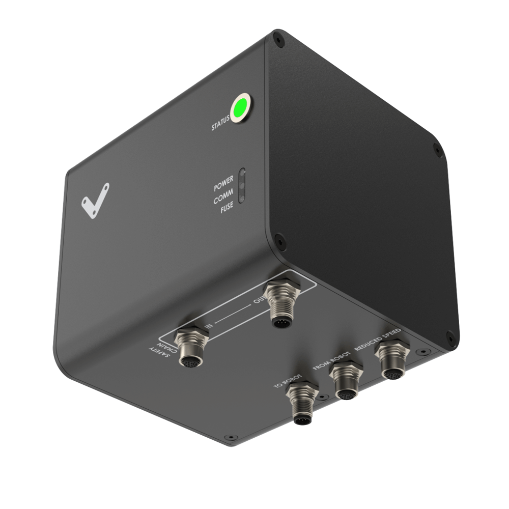
On-board LED for power, fuse, and communication status indication, located on the bottom of the module
LED indicator displaying power status, fault alerts, safety status, and activation of an emergency stop triggered by the module
Publishes safety state to MachineMotion V2
Included cables
1x Safety Extension cable - CE-CA-102-5001__2
1x Robot Safety Module “TO ROBOT” cable - CE-SA-111-0001
1x MachineMotion 2 Safety IN Pigtail cable - CE-CA-105-2000
1x Safety Jumper - CE-SA-102-0001
Safety
.png)
Vention’s safety modules perform safety functions as a part of a whole installation or machine. A complete safety system normally includes sensors or input units, logic units and contactors or output units. The manufacturer of the installation or machine is responsible for ensuring proper functioning of the whole system. The total concept of the control system into which the safety module is integrated must be validated by the user. Vention cannot guarantee all specifications of an installation or a machine without being responsible for the risk assessment and the design of the safety system. Vention takes over no liability for recommendations which are given or implied in the following description.
The following items must be taken into consideration during the design, risk assessment & installation of the safety system :
The Safety Modules shall be put into operation only after the safety functions have been tested during the commissioning.
According to EN IEC 60204-1:2018 and EN ISO 10218-1:2011 it is not allowed to restart automatically after emergency stop. Therefore the control systems of the connected devices have to disable the automatic start after emergency stop.
Opening the Safety Module or implementing unauthorized changes voids any warranty.
.png)
Functional error! Danger to life, risk of serious injuries or property damage
The Robot Safety Module may only be connected to the equipment listed in this manual;
The Robot Safety Module should be the last equipment in the safety chain. i.e. the device connected to the MachineMotion. If this recommendation is not respected, the safety devices connected downstream of the Safety OUT port of the Robot Safety Module won’t stop the robot;
When several Robot Safety Modules are connected on the same safety chain, if a robot goes to an emergency stop, all robots connected to a Robot Safety Module located upstream in the safety chain won’t stop.
The Robot Safety Module shall be connected to a Robot according to its specific wiring diagram.
No emergency stop button shall be connected to the safety chain of the Reduced port;
The Robot Safety Module does not monitor the input redundant signals at the From Robot and Reduced ports. If the connected devices do not have monitoring of its output signals, the performance level of the safety function can be reduced;
As per IEC 60204-1:2018 and ISO 13850:2015, if an emergency stop button is connected to the safety chain of the Safety IN port, the STO_To-Robot signals of the To Robot port shall be connected to a safe input that brings the robot in a stop category 0 or 1;
The Smart Robot Safety Module is designed to operate in indoor environments without dust or high humidity. Dust and dampness may lead to malfunction. Do not install or operate the Safety Module outdoors;
Technical specs
General Specifications
Item | Specification |
|---|---|
Part Number |
|
Weight | 0.8kg |
Dimensions | 19.0 x 15.0 x 9.0mm |
Material |
|
Operating Temp | 0 to 40°C |
Electrical Specifications
Item | Specification |
|---|---|
Nominal input voltage | 24 VDC (Class 2 or SELV power supply* |
Input voltage range | 19.2 ~ 26.4 VDC |
Operating power consumption | 8.4 W |
Short circuit protection | Internal E-FUSE IC |
Max current allowed | 2 A |
Post-short current | 250 mA |
Release delay at 24 V | < 40 ms |
Note: In North America the Safety Module shall be supplied by a certified class 2 power supply. In Europe, the Safety Module must be supplied by an SELV circuit. When powered by the MachineMotion those requirements are met.
Physical Interface
 Figure 1: Physical Interface |
LED Indicators
Name | LED Color | Indicated (when ON) |
|---|---|---|
POWER | White | 24 VDC supplied to module |
COMM | White | EtherNet communication functional |
FUSE | Red | Module internal fuse tripped |
STATUS | Off | Disconnected |
STATUS | Green | Connected |
STATUS | White | Communication issue |
STATUS | Orange | Error |
STATUS | Red | E-Stop |
STATUS | Blinking Red | User triggered E-Stop |
STATUS | Blinking Blue | Reduced/Collaborative mode |
Functionality
The Robot Safety Module is an easy way to interface almost any robot brand with Safety equipment and a MachineMotion V2. The cables are connected to the robots interface to enable the Emergency stop and Reduced speed safety functions. This makes it so that the estop button on the robot pendant will stop the MachineMotion and that the estop from the MachineMotion module will also stop the robot.
The Connectivity of the Smart Robot Safety Module consists of a 5 port ethernet switch that connects the robot to the MachineMotion. The subnet of the safety in port is 192.168.5.0/24 and the address of the MachineMotion is 192.168.5.1. One reserved ip address in that subnet is 192.168.5.2 for the pendant, the rest is free to be used.
The reduced mode is optional. It can be implemented if the robot needs to go at a slower speed during an intervention by an individual.
A safeguard stop can be implemented using the reduced port and by wiring the robot differently. It is important to not put an emergency stop button on a safeguard stop line.
For Applications where reduced and safeguard stop would be needed, it would be possible with 2 Smart Robot Safety modules. No estop+reset module can be plugged into the reduced line/safeguard line.
Port definitions
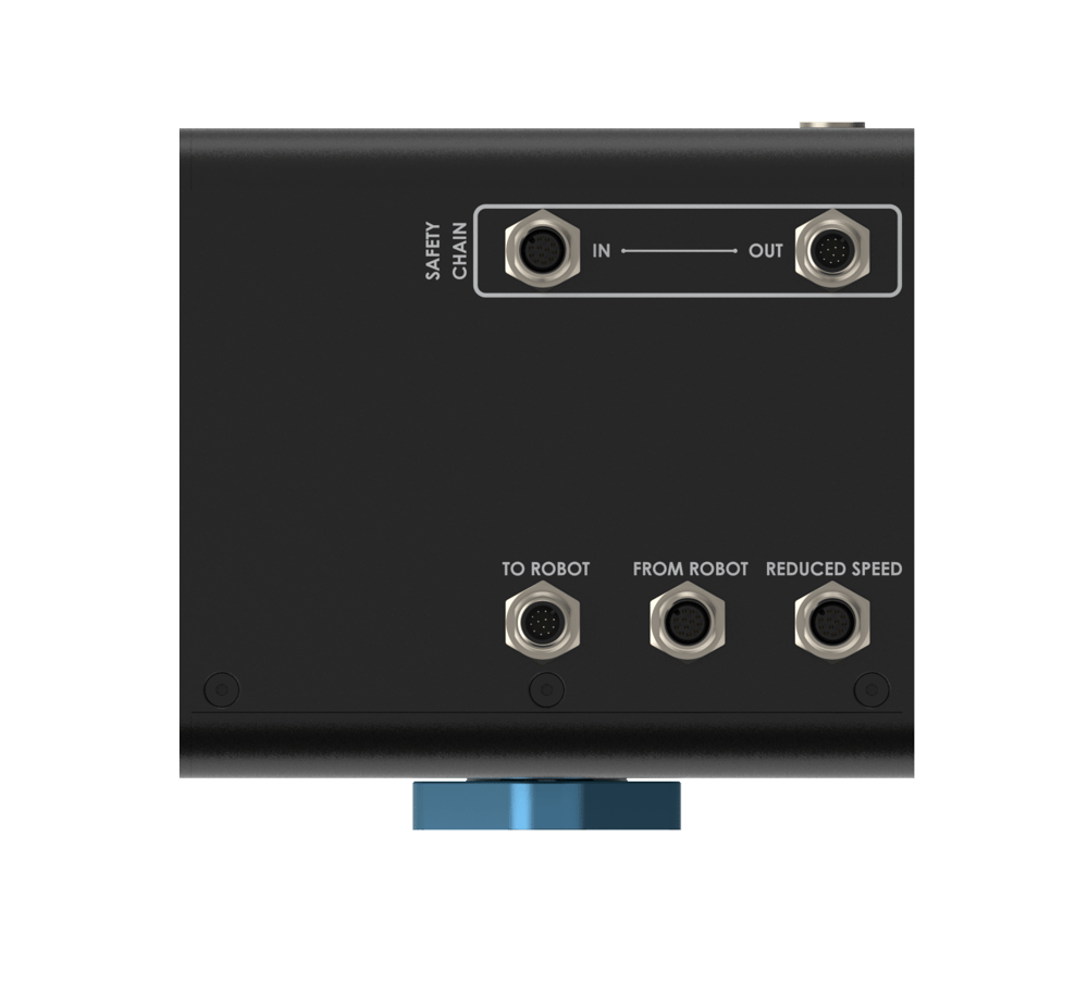 Figure 2: Robot Safety Module ports |
Safety OUT - Pin-out - M12, male, 12-pin, A-Keyed
The Safety OUT port connects to the SAFETY IN port of another Safety Module (if daisy-chaining multiple safety modules) or to a MachineMotionV2.
Pin | Function |
|---|---|
Pin 1 | 24 VDC |
Pin 2 | 0V |
Pin 3 | SAFETY OUT 11 |
Pin 4 | SAFETY OUT 12 |
Pin 5 | SAFETY OUT 21 |
Pin 6 | SAFETY OUT 22 |
Pin 7 | RESET +(24V) |
Pin 8 | RESET - (OUTPUT) |
Pin 9 | ETHERNET TX+ (auto-MDIX) |
Pin 10 | ETHERNET TX- (auto-MDIX) |
Pin 11 | ETHERNET RX+ (auto-MDIX) |
Pin 12 | ETHERNET RX- (auto-MDIX) |
Safety IN - Pin-out - M12, female, 12-pin, A-Keyed
The Safety IN port connects to the SAFETY OUT port of another Safety Module (if daisy-chaining multiple safety modules) or to an E-Stop and Reset Module (CE-SA-007-0000). IMPORTANT: If the SAFETY IN port is not used, insert the included yellow jumper.
Pin | Function |
|---|---|
Pin 1 | 24 VDC |
Pin 2 | 0V |
Pin 3 | SAFETY IN11 |
Pin 4 | SAFETY IN 12 |
Pin 5 | SAFETY IN 21 |
Pin 6 | SAFETY IN 22 |
Pin 7 | RESET +(24V) |
Pin 8 | RESET - (INPUT) |
Pin 9 | ETHERNET TX+ (auto-MDIX) |
Pin 10 | ETHERNET TX- (auto-MDIX) |
Pin 11 | ETHERNET RX+ (auto-MDIX) |
Pin 12 | ETHERNET RX- (auto-MDIX) |
To Robot - Pin-out - M12, male, 12-pin, A-Keyed
Pin | Function |
|---|---|
Pin 1 | NC |
Pin 2 | NC |
Pin 3 | STO_TO_ROBOT 11 |
Pin 4 | STO_TO_ROBOT 12 |
Pin 5 | STO_TO_ROBOT 21 |
Pin 6 | STO_TO_ROBOT 22 |
Pin 7 | RESET 11 DRY contact |
Pin 8 | RESET 12 DRY contact |
Pin 9 | ETHERNET TX+ (auto-MDIX) |
Pin 10 | ETHERNET TX- (auto-MDIX) |
Pin 11 | ETHERNET RX+ (auto-MDIX) |
Pin 12 | ETHERNET RX- (auto-MDIX) |
From Robot - Pin-out - M12, female, 12-pin, A-Keyed
Pin | Function |
|---|---|
Pin 1 | STO_IN (24V) |
Pin 2 | STO_IN (24V) |
Pin 3 | unplanned stop |
Pin 4 | delay reduced |
Pin 5 | 0V |
Pin 6 | REDUCED OUT 11 |
Pin 7 | REDUCED OUT 12 |
Pin 8 | REDUCED OUT 21 |
Pin 9 | REDUCED OUT 22 |
Pin 10 | NC |
Pin 11 | NC |
Pin 12 | NC |
Reduced - Pin-out - M12, female, 12-pin, A-Keyed
Pin | Function |
|---|---|
Pin 1 | 24V (fused) |
Pin 2 | 0V |
Pin 3 | REDUCED IN 11 |
Pin 4 | REDUCED IN 12 |
Pin 5 | REDUCED IN 21 |
Pin 6 | REDUCED IN 22 |
Pin 7 | RESET + (24V) |
Pin 8 | RESET - (RESET SIGNAL) |
Pin 9 | ETHERNET TX+ (auto-MDIX) |
Pin 10 | ETHERNET TX- (auto-MDIX) |
Pin 11 | ETHERNET RX+ (auto-MDIX) |
Pin 12 | ETHERNET RX- (auto-MDIX) |
Mounting
Install the module mounting bracket (CE-HW-005-1002) to the extrusion with the screws provided (HW-FN-003-0018). Install the module onto the mounting bracket as illustrated below.
.png) Figure 3: Module Mounting | .png) Figure 3: Module Mounting |
Wiring Diagrams with MachineMotion
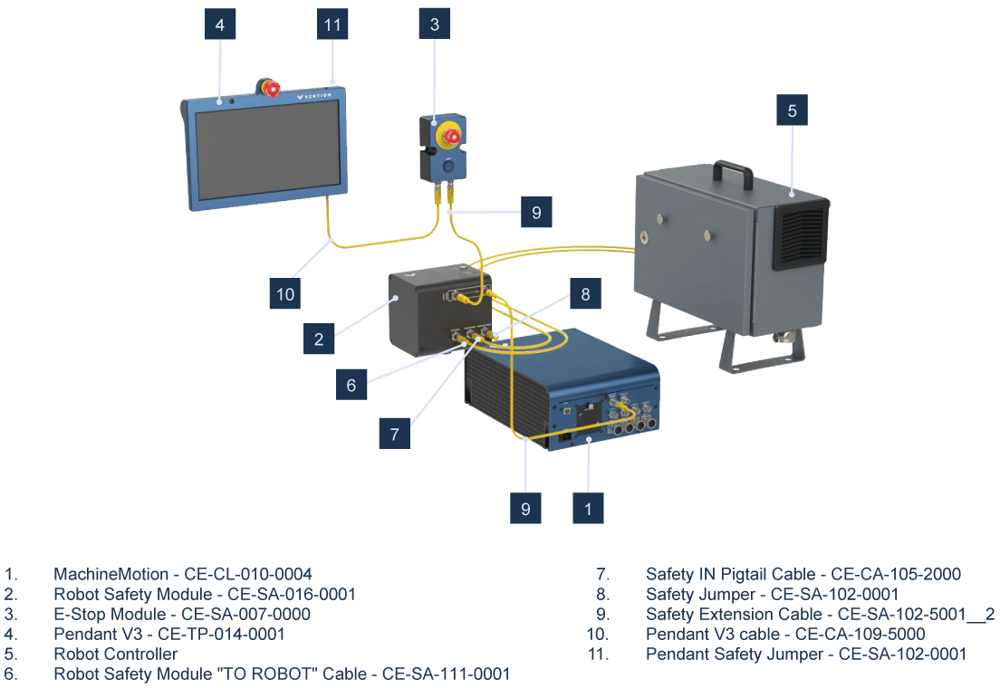 Figure 4: Robot Safety Module wiring diagram |
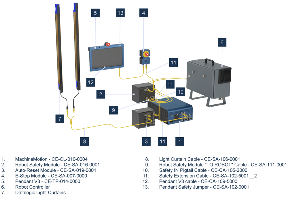 Figure 5: Robot Safety Module wiring diagram with Muting Safety Module (CE-SA-015-0001) |
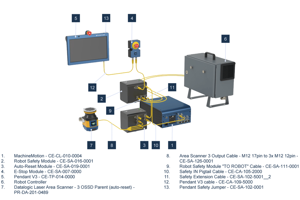 Figure 6: Robot Safety Module wiring diagram with Auto-Reset Module (CE-SA-019-0001) |
*Note: Insert a black jumper into any unused input on this safety module for proper functionality. Yellow jumpers are reserved for unused safety ports on MachineMotion.
Wiring Diagram without MachineMotion
The Robot Safety Module (no MachineMotion) CE-SA-016-0002 can be used when there is a need for a heads up signal to place Cobot in collaborative mode. The Robot Safety Module (no MachineMotion) CE-SA-016-0002 can be used when our Safety Module features are considered for an application (muting, mode-switching or auto-reset).
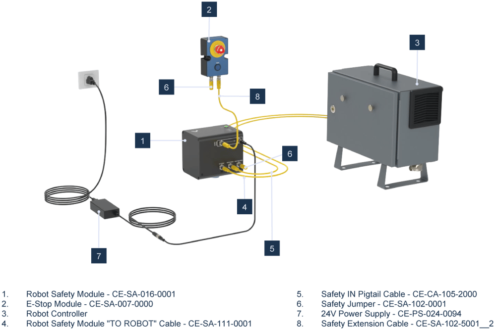 Figure 7: Robot Safety Module without MachineMotion |
Robot Controller wiring diagrams
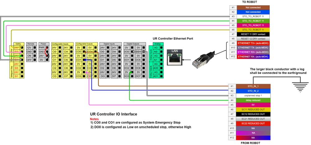 Figure 8: Robot Safety Module with UR Controller wiring diagram |
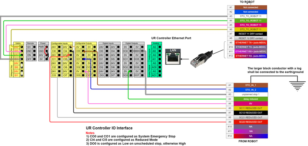 Figure 9: Robot Safety Module with UR Controller wiring diagram (reduced optional) |
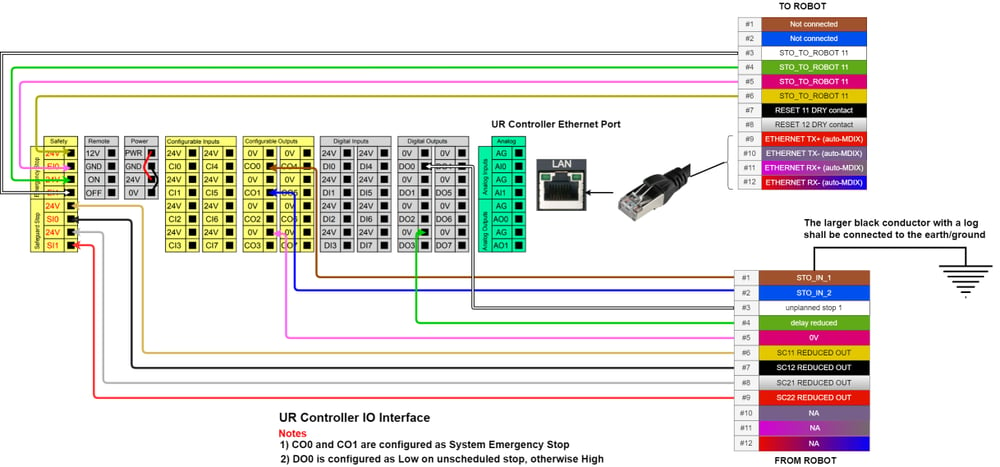 Figure 10: Robot Safety Module with UR Controller wiring diagram (estop+safeguard) |
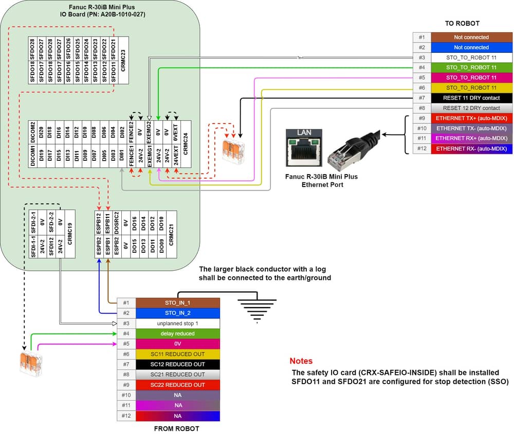 Figure 11: Robot Safety Module with Fanuc R-30iB Mini plus controller wiring diagram |
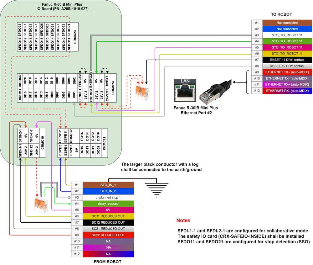 Figure 12: Robot Safety Module with Fanuc R-30iB Mini plus controller wiring diagram (Reduced) |
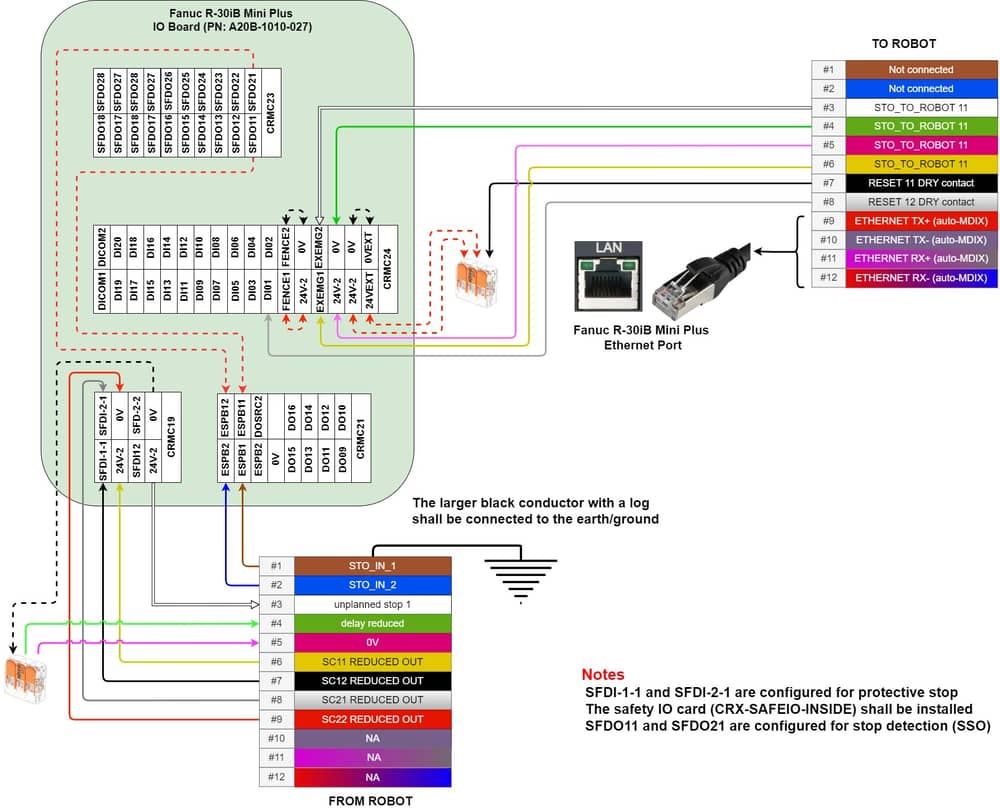 Figure 13: Robot Safety Module with Fanuc R-30iB Mini plus controller wiring diagram (Protective stop) |
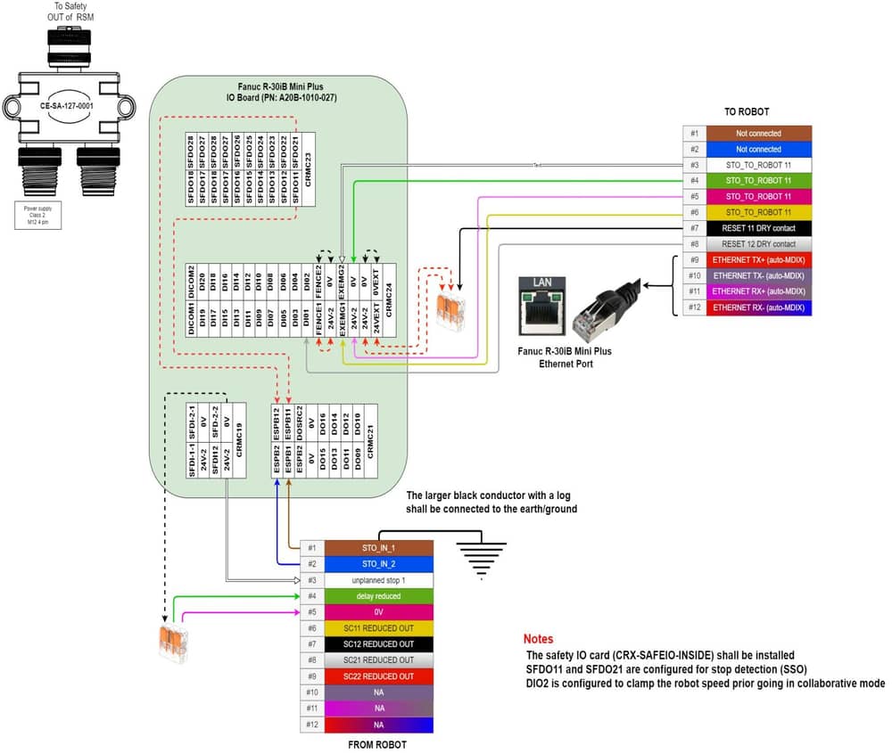 Figure 14: Standalone Robot Safety Module with Fanuc R-30iB Mini plus controller wiring diagram |
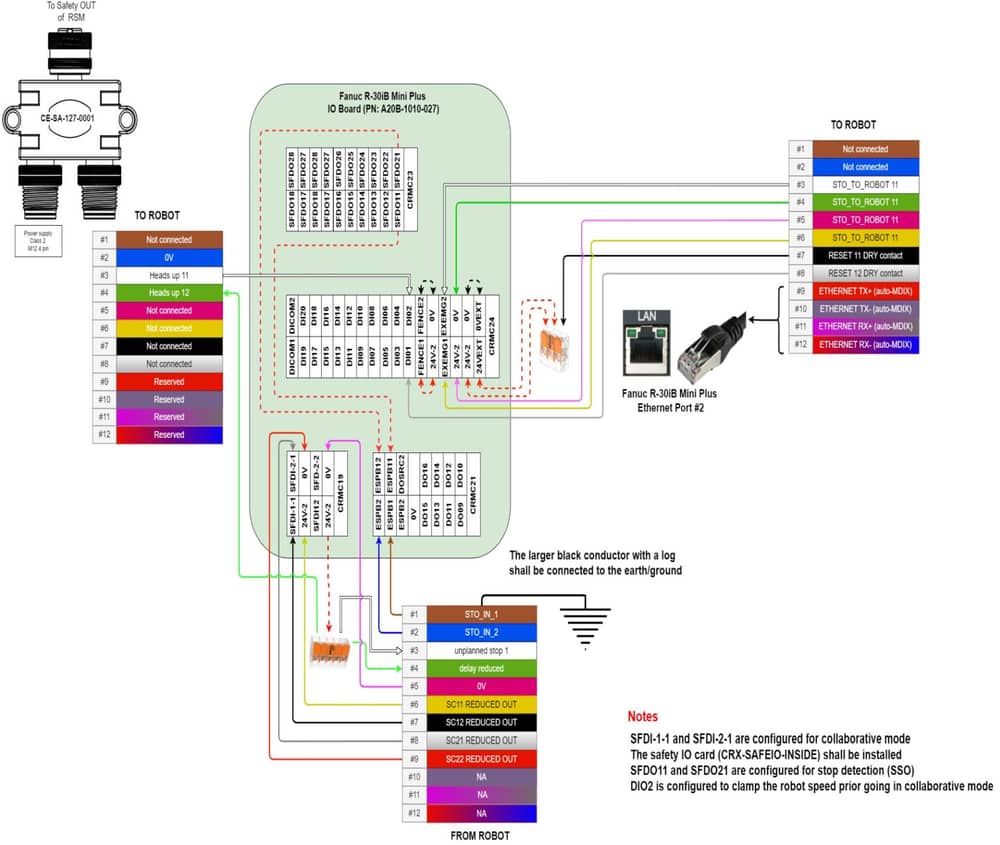 Figure 15: Standalone Robot Safety Module with Fanuc R-30iB Mini plus controller wiring diagram (Reduced) |
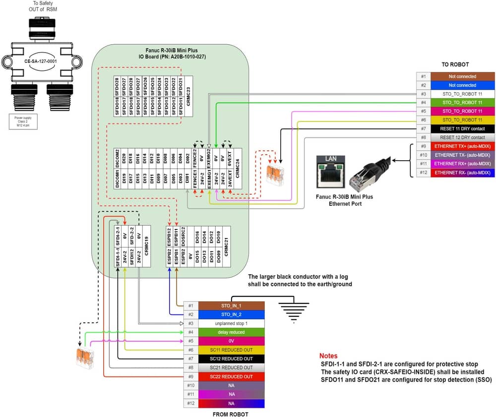 Figure 16: Standalone Robot Safety Module with Fanuc R-30iB Mini plus controller wiring diagram (Protective stop) |
Important information
Shorting or overloading the reduced port could trip the electronic fuse. To reset the fuse, a power cycle is needed.
No emergency stop button should be placed on the reduced port.
Safety Data
The Robot Safety Module realizes the following safety functions :
System emergency stop output at the Safety OUT port from the Safety IN port (Estop_SafetyIN-to-SafetyOUT);
System emergency stop output at the To Robot port from the Safety IN port (Estop_SafetyIN-to-Robot);
System emergency stop output at the Safety OUT port from the From Robot port (Estop_FromRobot);
Redundant safe signal at the From Robot port from the Reduced port (Reduced_FromRobot);
System reset propagation from the Safety IN port to the Safety OUT port (Reset_SafetyOUT); and
System reset propagation from the Safety IN port to the To Robot port (Reset_ToRobot).
For each of these functions, safety data can be found in the following table.
Safety Function | PL | Cat. | MTTFd | DCavg | PFHd |
|---|---|---|---|---|---|
E-stop_SafetyIN-to-SafetyOUT | e | 3 | 186 | 99% | 4.29E-08 |
Estop_SafetyIN-to-Robot | e | 3 | 186 | 99% | 4.29E-08 |
Estop_FromRobot | e | 3 | 186 | 99% | 4.29E-08 |
Reduced_FromRobot | e | 3 | 186 | 99% | 4.29E-08 |
Reset_SafetyOUT | c | 1 | >100 | N/A | 1.14E-06 |
Reset_ToRobot | c | 1 | >100 | N/A | 1.14E-06 |
The above information have been calculated based on the following operation conditions:
Data | Value | Unit |
|---|---|---|
dop | 365 | days/years |
hop | 24 | hours/days |
tcycle | 8640 | s/cycle |