|
Overview
The Momentary Pushbutton Module, CE-MD-014-0001, extends MachineMotion 2’s functionality with two momentary pushbuttons. This plug-and-play module only requires a single connection to the MachineMotion 2 controller. Compatible modules, such as the Power Switch (CE-MD-005-0000) & additional pushbutton modules can also be daisy chained to each other, making it possible to connect up to eight modules per MachineMotion 2 controller.
For details on Vention’s Latching Pushbutton Module, refer to the ‘Documentation for Previous Product Versions’ section at the bottom of this page.
Features
Includes two momentary pushbuttons
Connects (daisy chain) with compatible modules
Configurable address
Technical Specifications
General Specifications
Part Number | CE-MD-014-0001 |
Certifications |
|
Weight | 0.45 kg |
Dimensions | 46 x 88 x 133.0 mm |
Material |
|
Operating Temperature | 0 to 40°C |
Included in the Box |
|
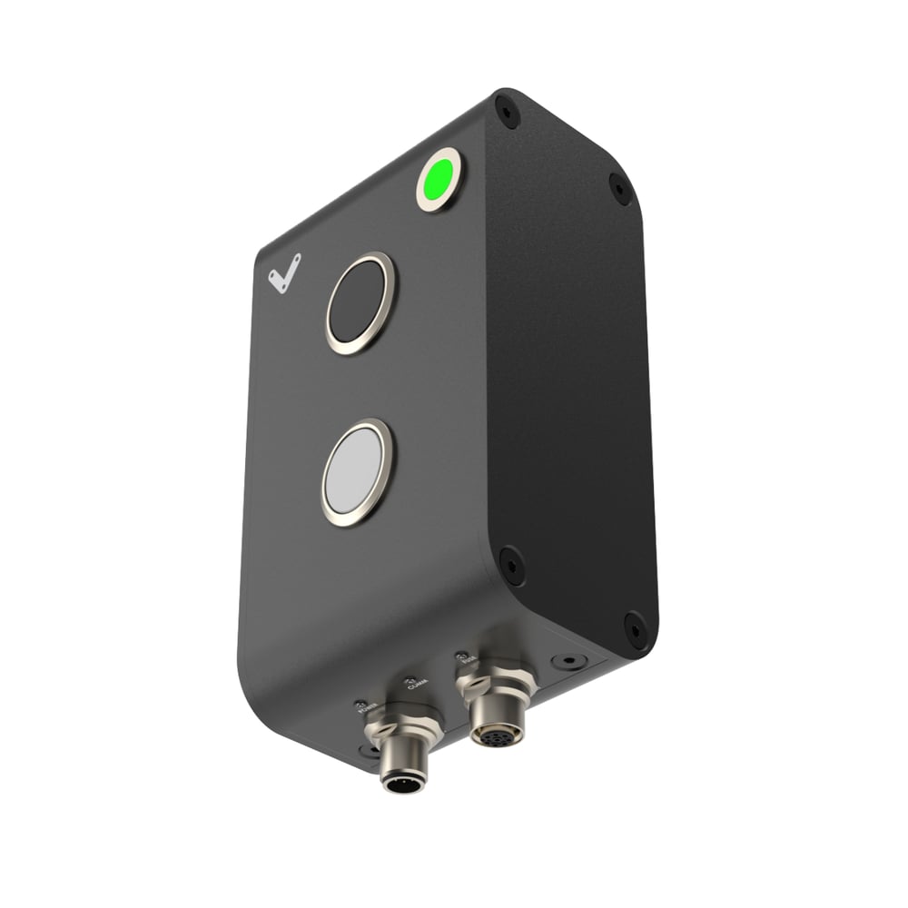
Momentary Pushbutton Module Physical Interface
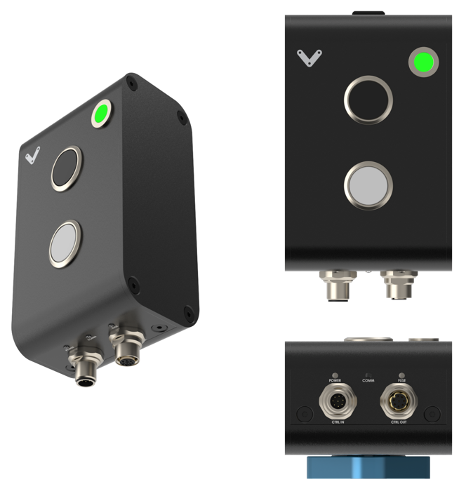 Figure 1: Physical interface |
Status LED Indicators
Name | LED Color | Indicated (when ON) |
|---|---|---|
POWER | White | 24 VDC supplied to module |
COMM | Yellow and Blue | RS-485 communication functional |
FUSE | Red | Module internal fuse tripped |
Pushbuttons (black/white)
Pushbutton type | Momentary |
Mechanical life (minimum) | 250,000 operations |
Connecting to a MachineMotion V2 Controller
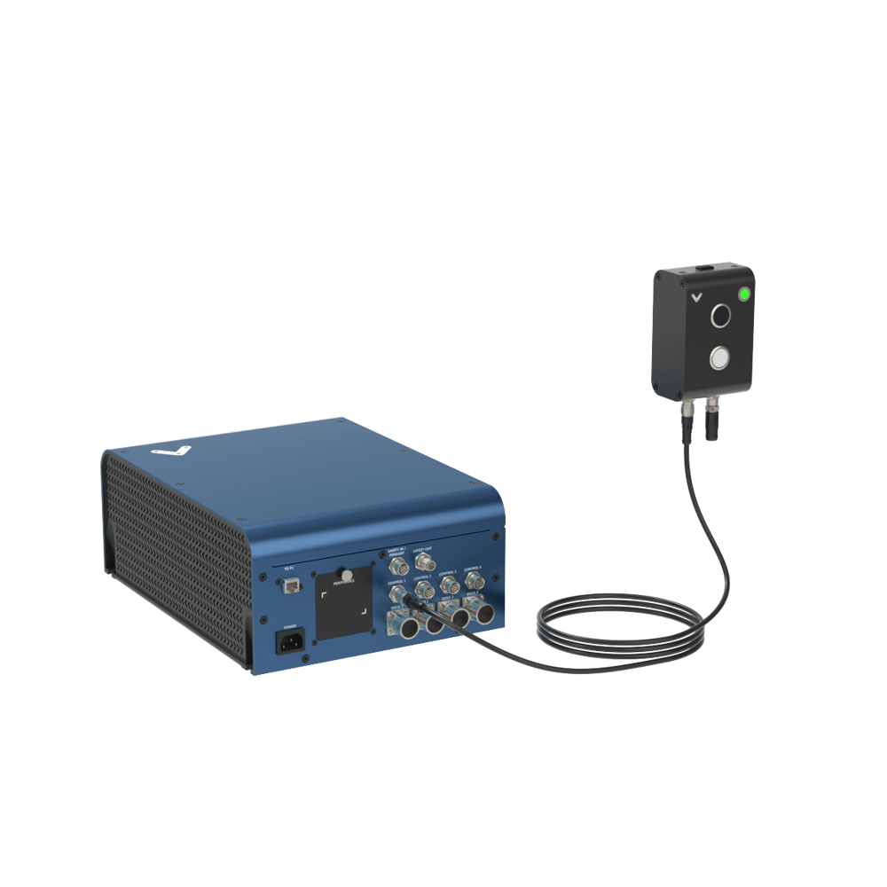 Figure 2: Momentary Pushbutton module with MachineMotion V2 |
CTRL IN Male M12 connector pinout
Pin | Description |
|---|---|
Pin 1 | 24 VDC (input) |
Pin 2 | Ground (input) |
Pin 3 | RS-485 A (input) |
Pin 4 | NRS-485 B (input) |
Pin 5 | Reserved |
Pin 6 | Reserved |
Pin 7 | N/A |
Pin 8 | Reserved |
CTRL OUT Female M12 connector pinout
Pin | Description |
|---|---|
Pin 1 | 24 VDC (output) |
Pin 2 | Ground (output) |
Pin 3 | RS-485 A (output) |
Pin 4 | NRS-485 B (output) |
Pin 5 | Reserved |
Pin 6 | Reserved |
Pin 7 | N/A |
Pin 8 | Reserved |
MQTT Topics
Topic | Message | Type | Description |
|---|---|---|---|
|
| READ | true if the device is available/connected |
|
| READ | Hardware Revision |
|
| READ | firmware Revision |
|
| READ | State of the black button on top |
|
| READ | State of the white button on the bottom |
|
| WRITE | Sets the LED colors. 0=OFF, 1=ON |
MachineLogic Sequence Example
Sequence example to handle a button being pushed and to change the LED color of the device to Green:
Topic for Wait For Event:
If Black Button: devices/push-button-v2/+/digital-input/0
If White Button: devices/push-button-v2/+/digital-input/1
Message: 1
Topic for Output Generate Event:
devices/push-button-v2/+/set-led
Message: {“red”:0,”green”:1,”blue”:0}
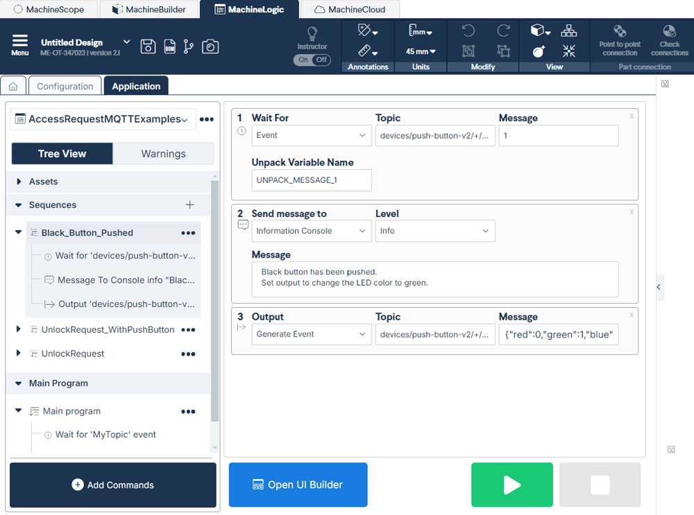 Figure 3: MachineLogic example to handle a button being pushed and to change the LED color of the device |
How to replicate the LED color of the Access Request Module on the Momentary Pushbutton
If you are using the Momentary Pushbutton in conjunction with an Access Request Module (CE-SA-017-0001) you can use the example below to ensure that the LEDs have the same behavior. Follow these steps below:
Find your **Device ID **as defined in Table 1 below
Find your Serial Number on the back of the Access Request Module
Add your Device ID & Serial Number in the example below
Momentary Pushbutton module address configurations
Below are the valid address configurations that can be used for the Pushbutton module
Valid address configurations
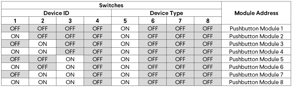 Table 1: Address Configuration |