

User manual
Updated: Tuesday, August 10th 2021
MachineMotion Controller Safety Guide (V1E0+)
MachineMotion Safety
v1.0
Overview
This guide describes the safety configurations of MachineMotion V1E0 and later V1 versions. It also shows how to connect MachineMotion to Vention safety peripherals and have a functional safety configuration.
The goal of the safety system is to power off all actuators connected to the MachineMotion controller immediately upon an E-stop event.
MachineMotion Safety IO
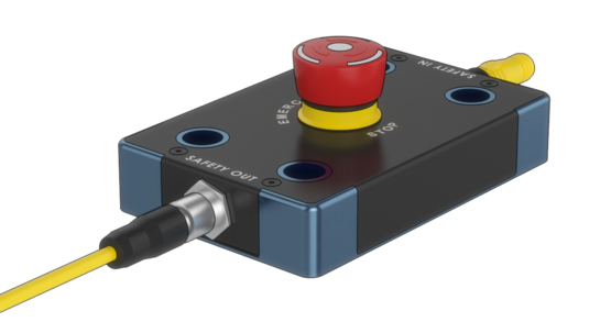
Three main components dictate the safety configuration of the MachineMotion: The E-stop button, the SAFETY IN and the SAFETY OUT plugs. These components are illustrated in the figure below.
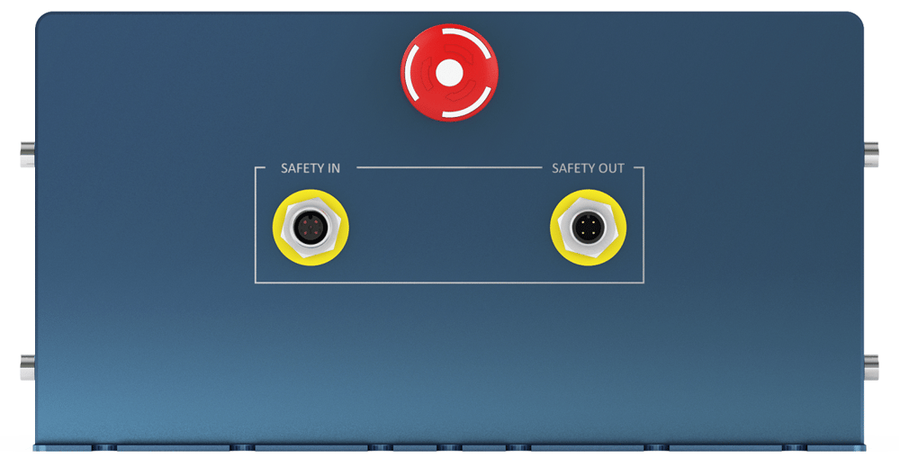
The following table describes the functionality of each component
| MachineMotion connector | Description |
|---|---|
| SAFETY IN | Used to connect other safety devices that can place MachineMotion in an emergency stop mode (This input should be fed by a redundant dry contacts) |
| SAFETY OUT | Used to trigger and place other devices in an emergency stop mode (redundant dry contacts, normally closed) |
| E-stop button | When pressed, the E-stop button places the system in emergency stop mode. Needs to be released to disengage the emergency stop mode. |
Status LED Indications
To understand the status LED, please refer to the table below:
 |
MachineMotion controller is booting up |
 |
MachineMotion controller is ready to run |
 |
MachineMotion controller is not ready to run. This means that the physical e-stop on the MachineMotion controller is triggered, or the software e-stop is on. |
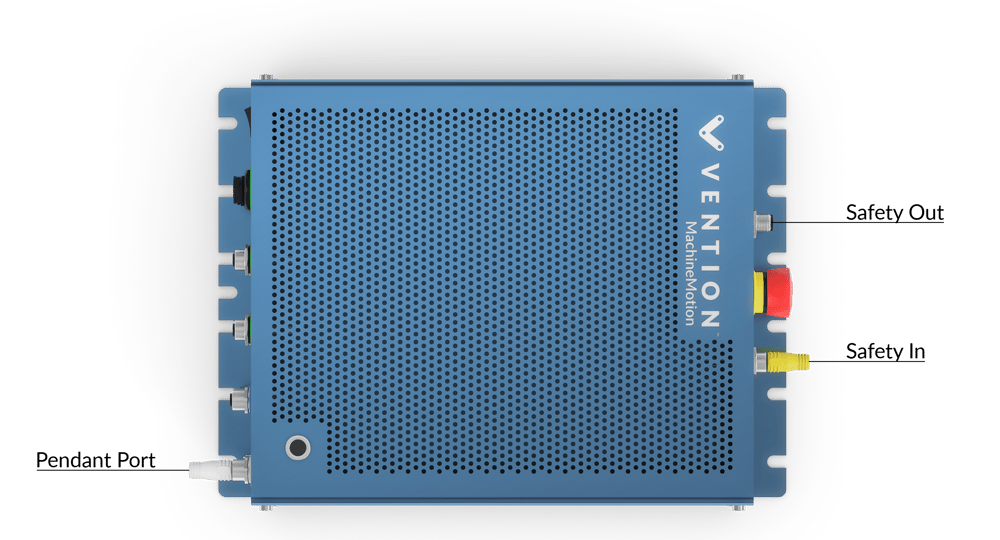
Safety Setup Jumpers
The safety setup of the MachineMotion requires you to connect a device to the SAFETY IN and to the PENDANT port. These ports cannot be left unconnected; otherwise, they will trigger an emergency stop mode in the MachineMotion. Follow the instruction below to setup your MachineMotion
- If you do not have any system to connect to the SAFETY IN, you need to insert the appropriate yellow jumper in the SAFETY IN plug.
- If you are not using a pendant, insert the white jumper in the pendant plug on the front panel of the MachineMotion
MachineMotion Behavior in Emergency Stop Mode
The emergency stop mode is engaged either by an E-stop button (located on the MachineMotion controller or on the pendant), the SAFETY IN port or a software E-Stop.
When MachineMotion enters the emergency stop mode:
- The SAFETY OUT dry contact opens
- The motors drive loses power, and the motors are not powered anymore
- The IO modules and encoders connected to the AUX ports do not lose power; the outputs conserve the same logical state as they were before the emergency stop
- The brakes, connected to an AUX port, lose power and lock the axis
- MachineLogic program keeps executing in the background, but no drives will be engaged. However, there is a way to terminate the program (refer to the section: MachineLogic Software Termination)
- Python programs will keep executing, but you can control the behavior of your application upon E-stop using the function bindeStopEvent(callback_function)
MachineLogic Software Termination and IO Sate
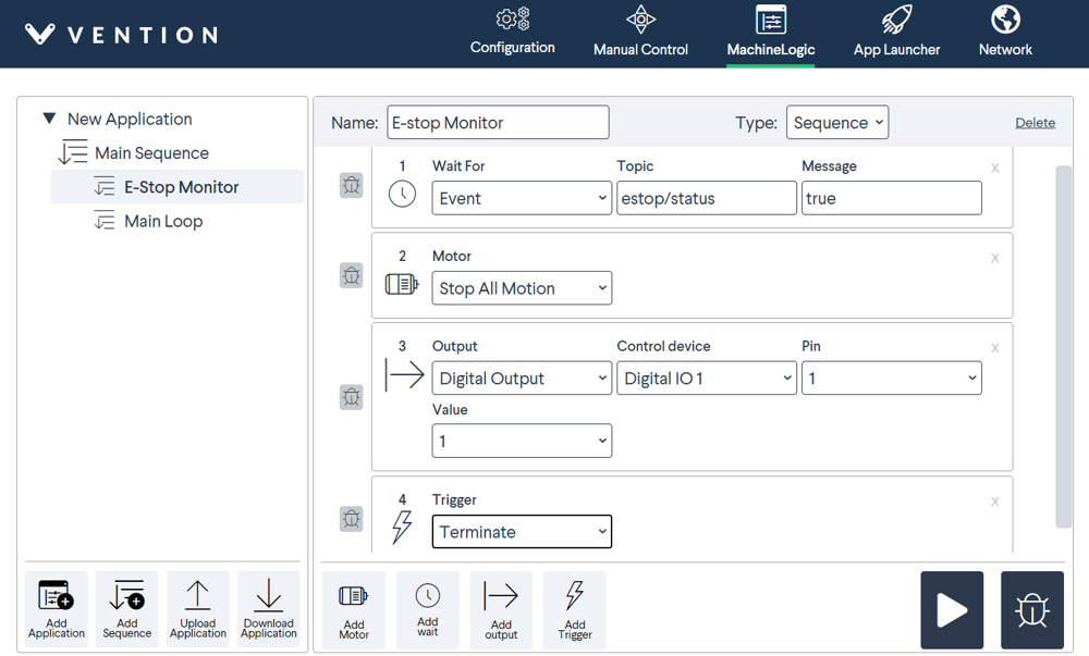
To terminate the application after an emergency stop event in MachineLogic, you must monitor the estop topic in the MachineLogic program, then use the “Terminate” instruction.
This will also allow you, for example, to reset the outputs to a safe states before stopping your application. To do so, in your application, follow the instructions below and refer to the image of the MachineLogic:
- Create a child sequence named “E-stop Monitor”
- Set the sequence type to sequence
- Click on Add Wait, then use the drop down menu to select Wait for Event
- Add “estop/status” to the Topic text box and “true” to the Message text box
- Add the Stop All Motion instruction
- Set outputs to the desired safe state
- Add the Terminate instruction
The next step would be to add the child sequence to the main sequence. This will ensure that it is running in the background and that it will be executed once an emergency stop occurs:
- Go to the Main Sequence
- Add a Trigger instruction. This should be the first instruction of the code
- Under Sequence Name select E-stop Monitor
- Add your program
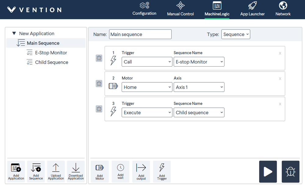
This program will run in the background, and when an E-stop is engaged, the IO modules will be set to the desired state, and the MachineLogic code will terminate.
When disengaging the emergency state, the IO remains at the desired state because this was the last state before the termination of the MachineLogic code.
Wiring Vention Safety Peripherals
Emergency Stop Switch
The goal of the emergency stop switch CE-SA-003-0000 is to power off all actuators connected to the MachineMotion controller immediately.
The following table details the connectors and the wiring of the emergency stop switch.
| Emergency stop switch connectors | Description |
|---|---|
| SAFETY IN | Used to connect other safety devices in series with the emergency stop switch. Note: if you do not have any system to connect to this port, you need to place the appropriate yellow jumper on the SAFETY IN plug. |
| SAFETY OUT | Used to trigger and place MachineMotion in an emergency stop mode. Needs to be connected to MachineMotion SAFETY IN. |
| E-stop button | When pressed, it places the system in emergency stop mode. Needs to be released to disengage the emergency stop mode. |
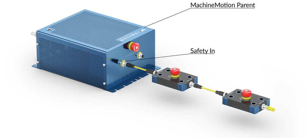
The SAFETY OUT of the emergency stop switch needs to be connected to the MachineMotion SAFETY IN, as seen in the figure below.
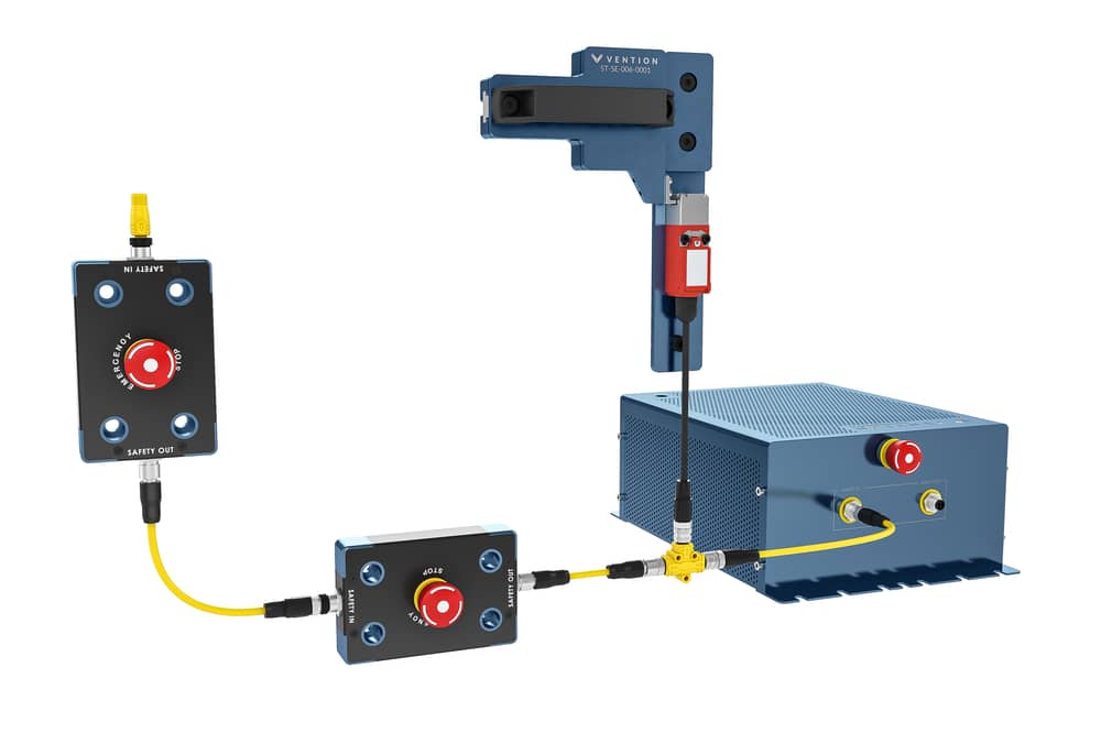
Please note, if you want to use multiple emergency stop switches, you have to connect them in series. Beware of connecting the SAFETY IN of the first switch to the SAFETY OUT of the second. Refer to the figure below to do so
The emergency stop switch, once connected to the MachineMotion, acts like the E-stop button present on the MachineMotion itself.
Please note, if you are using multiple MachineMotion controllers, you should connect the emergency stop switch to the Parent MachineMotion. This will ensure that the emergency stops are at the top of the chain and will trigger an emergency stop for the entire system.
For more details about connecting multiple MachineMotion, refer to the Wiring Multiple MachineMotion section.
Safety Interlock Switch
The safety interlock gate bolt ST-SE-006-0001 is designed to ensure that your machine is operational only when its gate is properly closed. Alternatively, the safety interlock switch CE-SA-010-0000 can be used where manual locking of the enclosure, such as through the use of a gate bolt, is not required.
Every safety interlock switch is provided with a 4-pin M12 connector, a 3-meter safety extension cable CE-CA-028-3000, a jumper and a safety divider. The jumper is used when only one interlock is in use. The safety divider is used for connecting another safety device.
The safety divider has 2 identical ports and 1 port that will be connceted to the MachineMotion.
Follow the instructions in the table below to connect your safety interlocks to the MachineMotion.
| Safety Divider Ports (4-pin M12) | Description |
|---|---|
| Port 1 | Connect this port to the SAFETY IN of the MachineMotion |
| Port 2 | Connect the interlock cable to this port |
| Port 3 |
|
Note: Connect a jumper to all unconnected ports of all the safety dividers.
Wiring Multiple MachineMotion
If you are using a system with multiple MachineMotion controllers, it is advised to connect their safety systems togehter.
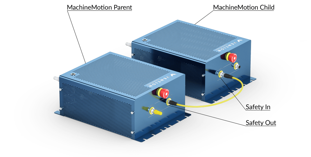
It is recommended to use the Parent and Child configuration, as shown in the figures below.
Furthermore, when using this configuration, ensure to connect all safety peripherals to the Parent MachineMotion. In this case, these safety systems will trigger the emergency stop mode on the Parent MachineMotion; thus, they will trigger an emergency stop in the entire system.
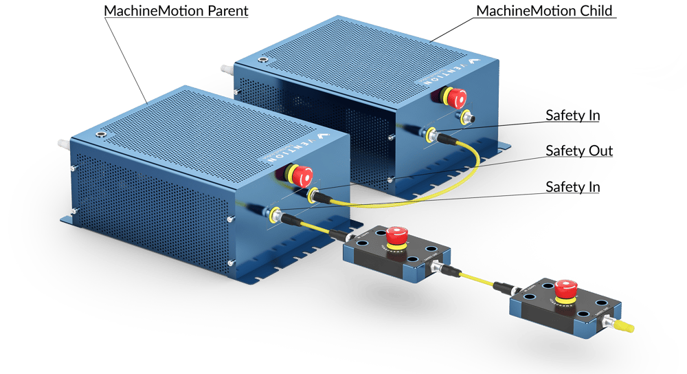
Parent and Child Configuration Wiring
- Connect the SAFETY OUT of the Parent controller to the SAFETY IN of the Child controller.
- If you are not using any safety peripherals, put the yellow Safety Jumper on the SAFETY IN plug of the Parent MachineMotion. Refer to the first image below.
- If you are using safety peripherals, such as emergency stop switches or interlocks, connect them to the SAFETY IN plug of the Parent MachineMotion. Refer to the second image below.
- Note, the SAFETY OUT port can be left unconneted, as it is an output and will not trigger an emergency stop.
In addition, if you have more than two MachineMotion, you need to connect the SAFETY OUT of the second MachineMotion to the SAFETY IN of the third MachineMotion.
Behavior of the Parent and Child Safety Configuration
In this configuration, the E-stop button of the Child controller does not control the entire system.
If the E-stop on the Parent controller is triggered, it will trigger the E-stop on the Child controller because the Parent controller SAFETY OUT is wired to the Child controller SAFETY IN. However, the E-stop on the Child controller will not trigger the E-stop on the Parent controller.
Note, it is recommended to remove the E-stop button on the Child controller. This will allow the Parent controller E-stop to be the only visible and attainable E-stop in the system. Please contact Vention Customer Success team for more support on this procedure.