MachineMotion Controller Manual
Contents
- Overview
- What is included with each MachineMotion
- Safety Notice
- Status LED
- Connecting Components
- Power on and set-up
- Actuator Software Configuration
- Actuator Hardware Configuration
- Testing your set-up using Control Center
- Cloud9 Integrated Development Environment
- MachineLogic
- Documentation for Previous Product Versions
Overview
MachineMotion 2 is an all-in-one automation controller. It contains the necessary components to rapidly create general motion control and automation projects. The controller allows connection for up to 4 step-servo motors, and external modules. On the software side, even users with limited programming experience can create automated machines. This user manual covers MachineMotion 2 V2.7.0 & Newer. For details on previous versions of MachineMotion 2 (V2.6.0 & Older) and MachineMotion 1, refer to the ‘Documentation for Previous Product Versions’ section at the bottom of this page.
MachineMotion v2 key features
- Control up to four 250 W high performance step-servos with accurate and automatic position adjustments. This allows the actuator to always reach the user-specified position, thanks to a built-in encoder that enables the motors to operate in closed control loops
- Step-servo junction box with simple cabling, where the brake, home and end-stop sensors can be directly wired to the motor
- Status light on servo motors and controller for quick diagnostics
- Loaded with code-free software including:
- Control Center
- MachineLogic
- Python
- Open source development tools including:
- Cloud 9 IDE
- Javascript
- Operator mode
- Manual joggers
- The MachineMotion 2 controller is certified to Canadian, US & European standards.
- IP30 rated enclosure for industrial applications, with active cooling and replaceable filters
- Connect digital I/O and analog modules to control I/O devices
- Single continuous flex cable to power an actuator, sensors and power-off brake
- Plug and play with all Vention actuators
- Native support for Universal Robots with URcap
- Plug and play safety system with physical and software reset
- Directly connect peripherals locally or remotely using the teach pendant, keyboard, mouse, and monitor
What is included with each MachineMotion
When you order a MachineMotion, the following items are included:
- MachineMotion Controller
- AC Power Cord (NEMA5-15P and CEE 7/7)
- Pendant jumper
- User Manual
- Safety cable with flying leads
- Note that a safety device is not included. If a safety device is needed, include an e-stop and reset module**
Safety Notice
MachineBuilder is a complete 3D-CAD platform that allows users to quickly design complex automation solutions. It needs to be noted that safe design principles and techniques are to be considered by the user. Although the MachineMotion controller is thoroughly tested and certified to international electrical safety standards, the end user is responsible for the safe installation of Vention’s products. To ensure safe operations of Vention products, it is required to perform a risk assessment before the installation and deployment of any Vention designed machine.
Before proceeding with the unboxing, installation and deployment of any Vention machine, the end user is required to read this manual. At all times, Vention’s Terms and Conditions should be respected. Vention Terms and Conditions can be found at https://www.vention.io/terms-of-use.
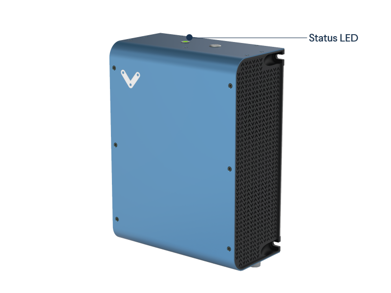
Status LED
Located on the top of the MachineMotion controller, there is a status LED to display the state of the controller.
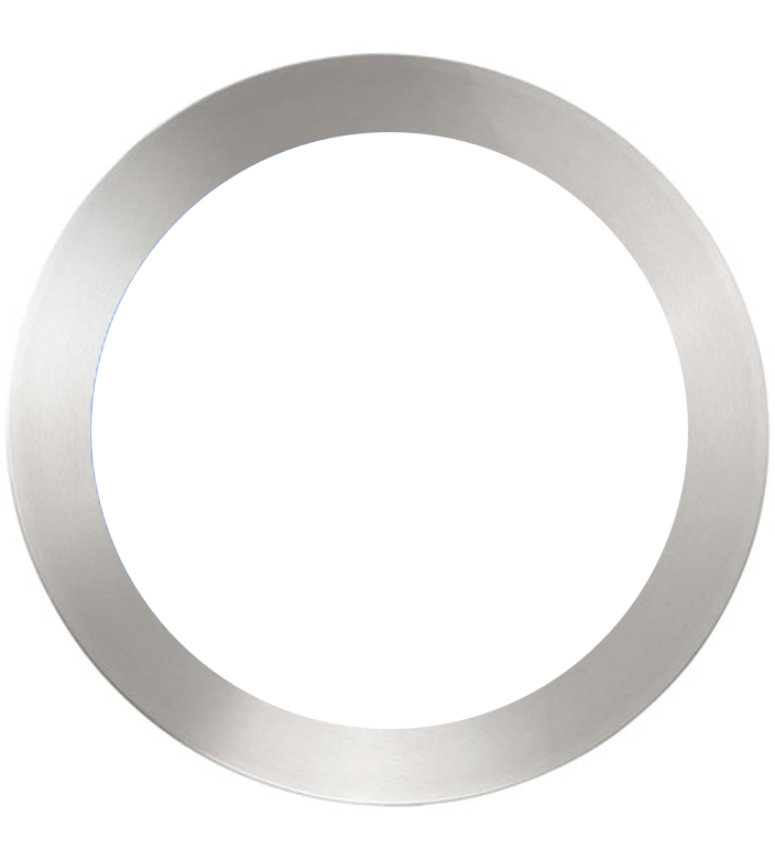
To understand the status LED, please see table below:
 |
MachineMotion controller is booting up |
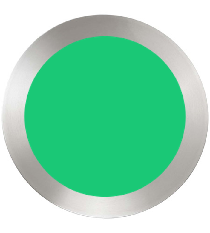 |
MachineMotion controller is ready to operate (e-stop inactive) |
 |
MachineMotion is running a script |
 |
MachineMotion controller is not ready to run: It is in an emergency stop state. This means that the physical e-stop on the MachineMotion controller is triggered or the software stop is on. |
Connecting Components
As shown in the two figures below, MachineMotion contains several connectors. Each connector is meant to be used for certain device types. Follow the figures and tables below to connect your components. Add jumpers to all unused SENSOR ports, the PENDANT port and the SAFETY IN port. The SAFETY IN and SAFETY OUT ports accept redundant dry contacts. Disconnect the power supply before connecting or disconnecting motor cables on any of the connector sockets. Failure to do so may result in serious injury and equipment damage.
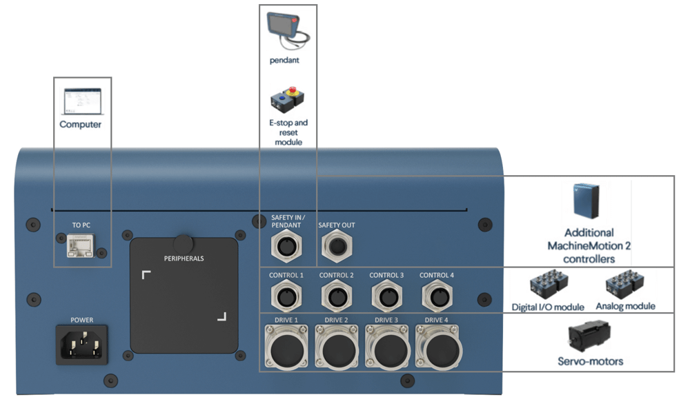
Vention automation components plugged to controller
| Device | Vention Part Number | MachineMotion Connector |
|---|---|---|
| Servo motors | MO-SM-01X-0000 | DRIVE1, DRIVE2*, DRIVE3*, DRIVE4* |
| Pendant | CE-TP-004-0001 | PENDANT |
| Control Modules | CE-MD-00X-000X | CONTROL1, CONTROL2, CONTROL3, CONTROL4 |
| Safety system input | Input used to place the system in emergency stop mode (redundant dry contacts). IMPORTANT: It is required to connect a safety device here. This could be an e-stop and reset module or another safety device that connects to the flying leads end from the safety cable. | Safety In |
| Safety system output | Output used to trigger the system inputs of other devices (redundant dry contacts) | Safety Out |
| Additional MachineMotion v2 controllers | CE-CL-010-0004, CE-CL-010-0001 | LAN1, LAN2 |
| Mouse & keyboard | Personal mouse, keyboard to operate MachineMotion V2 interface | USB |
| Monitor | Personal monitor to operate MachineMotion V2 interface | HDMI |
| MachineMotion v2 software update | Update MachineMotion v2 hardware with SD card | micro SD |
*Only available on CE-CL-010-0004
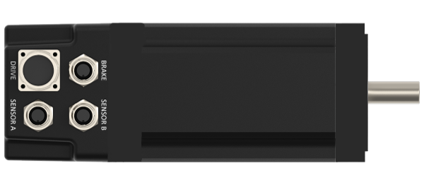
Vention automation components plugged to junction box
| Device | Vention Part Number | MachineMotion Connector |
|---|---|---|
| Brake | MO-PT-002-0001 | BRAKE |
| Home sensor | CE-SN-004-0001 | SENSOR A, SENSOR B |
| End-stop sensor | CE-SN-004-0001 | SENSOR A, SENSOR B |
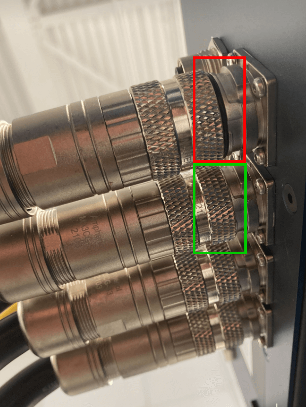
Once you connect the junction box to the MachineMotion, ensure that the connection is properly tightened as shown in the green box in the image below and avoid a connection similar to the one shown in the red box.
Communicating with the Controller
|
 |
|
 |
|
 |
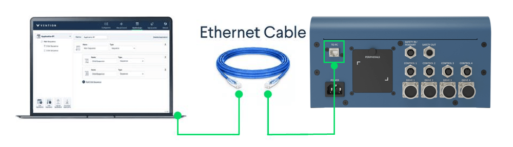
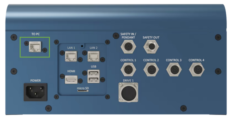
Method 1 - Peer to Peer Ethernet with Fixed IP
This method is most commonly used to get started. This method is used to connect a computer to MachineMotion in a peer-to-peer way (one to one connection).
Simply plug an Ethernet cable into the connector labelled “TO PC” and to your computer. If you do not have an Ethernet port on your computer, use the Ethernet-to-USB adapter provided with the controller.
Follow the steps in Power on and set-up to proceed with the software configuration.
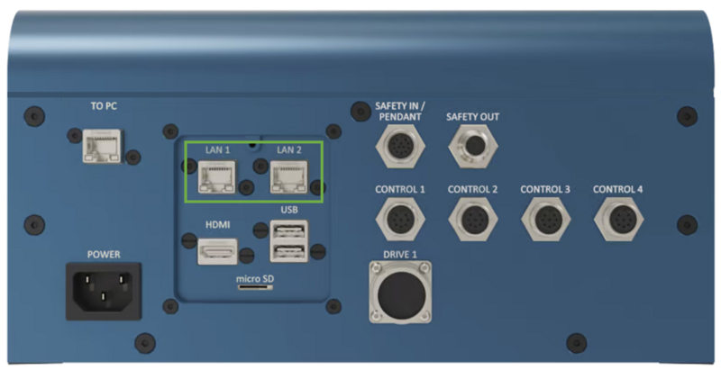
Method 2 - Standard Ethernet
Using the LAN1 and LAN2 ports are useful when connecting MachineMotion to a standard, multi-device Ethernet network. This use case becomes necessary when connecting multiple MachineMotion controllers together and when connecting MachineMotion on a LAN or WLAN.
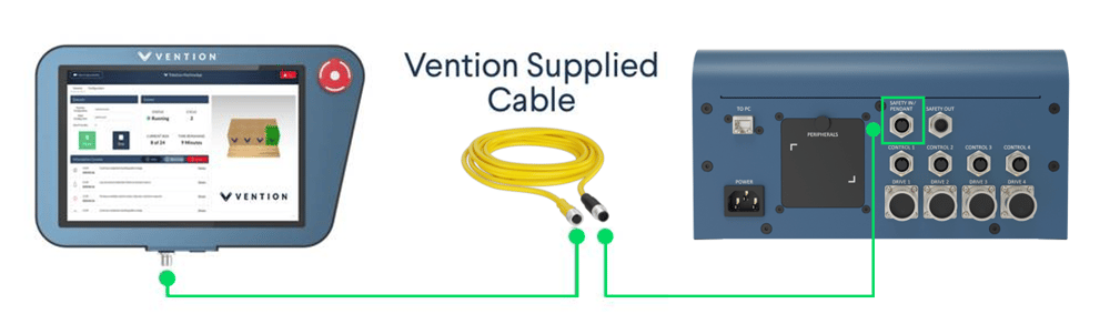
Method 3 - MachineMotion Pendant
The MachineMotion pendant allows users to have a configuration free connection to the controller. Simply connect the pendant in the PENDANT connector using its 12 pin M12 cable. If no pendant is present in the design, connect a safety jumper to the pendant port. Follow the steps in Power on and set-up, except the first and last step.
Power on and set-up
- Follow the steps below to set-up your controller.
-
Step 1: Connect a computer to the “TO PC” port and POWER ON the MachineMotion controller by switching on the POWER ON button. The status LED should display blue as it is booting up. Wait for the status LED to turn green (~ 90 seconds). Browse to 192.168.7.2 using Google Chrome.
-
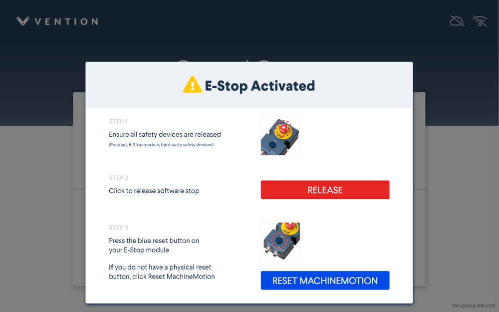
Step 2: The screen below will appear. Ensure you have released all physical e-stop buttons before proceeding. After, click “RELEASE” to disable the software stop. Click “RESET” when you are ready to operate the machine. This will verify that all configured drives are detected and properly energized. If the screen screen still appears after pressing “RESET”, check to ensure the pendant port has a jumper connected to it, if no pendant is present and ensure a safety system is properly connected into the “Safety-in” connector.
A variation of the screen below will appear if all configured drives detect a motor and the drives are able to properly energize. The status LED should also display green.
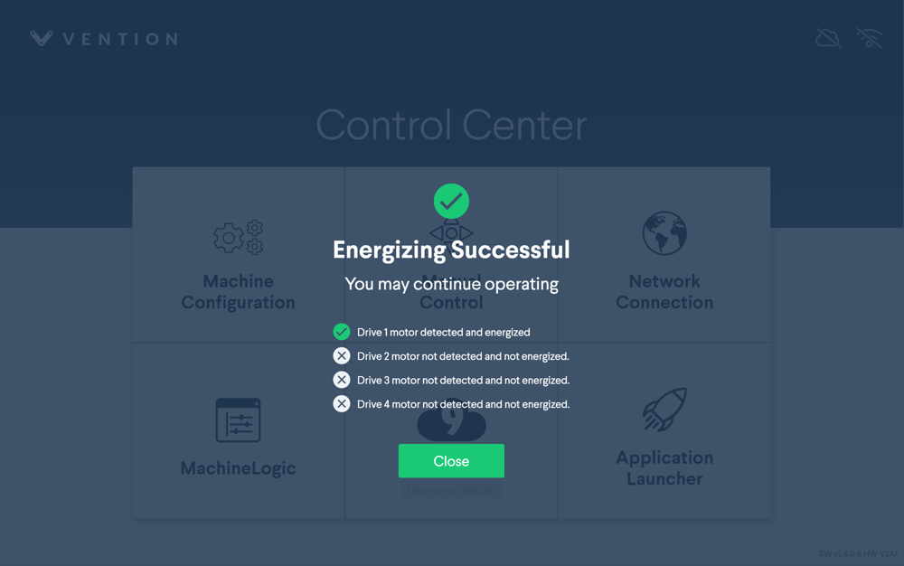
-
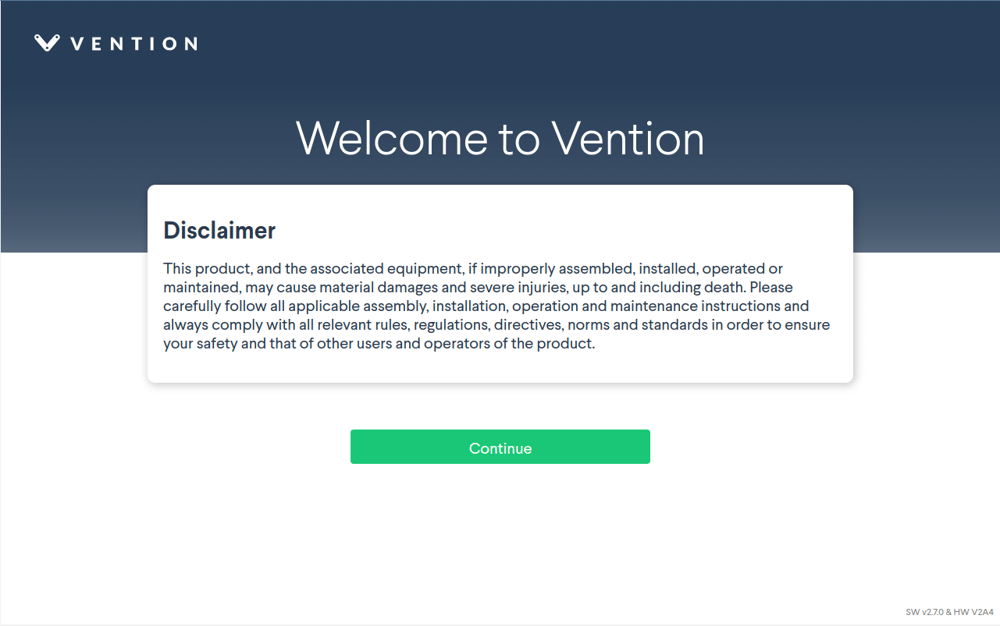
Step 3: Make sure you read through the Disclaimer before continuing. When you are ready, click “Continue”.
-
Step 4: Next, you must set a system level password. This password is used to access Cloud9, and use the command line. Enter and confirm your password. When this is complete, click “Set System Password”.
Note: Connecting both a Pendant and PC at the same time during the onboarding steps may lead to a blocked state on the Set System Password screen. It is recommended to do the onboarding on a single device before connecting to the second.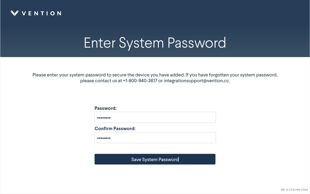
-
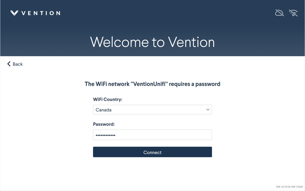
Step 5: If you are not using a Vention Pendant, skip ahead to Step 7. The wireless network page will appear. Select your wireless network from the list available. Select the “WiFi Country” from the dropdown menu, and fill-in your network password in the “Password” field. Click “Connect” when you’re done.
-
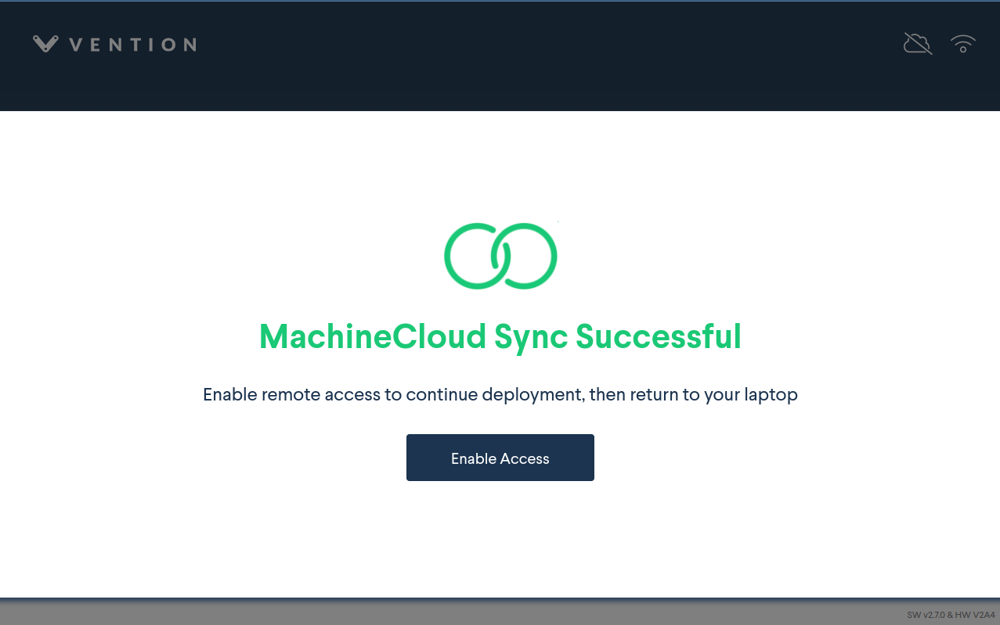
Step 6: If the network connection is successful and you’ve previously setup your MachineMotion with MachineCloud, you should see the successful sync screen below. You may chose to “Enable Access” now or later.
-
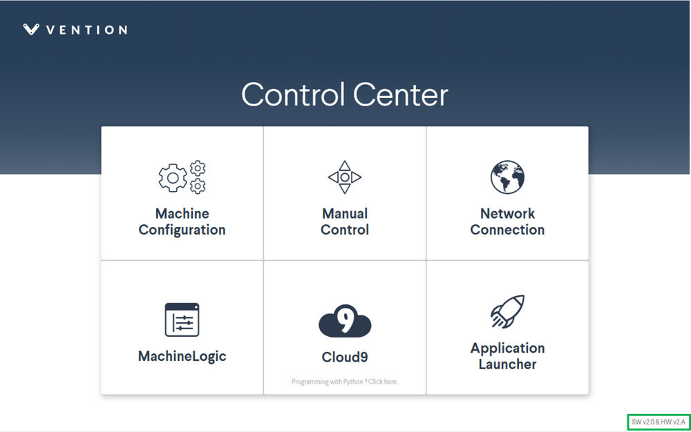
Step 7: The Control Center menu will appear and give access to the numerous MachineMotion functionalities. You are ready to configure. You could also check your software version at the bottom right-hand corner.
-
Actuator Software Configuration
The section below will give detailed information on how motors, end-of-travel sensors and linear actuators are configured in a Vention system.
For motion control to be possible, a position reference must exist. This is what homing refers to, the action of finding the position reference of an actuator. This position reference is also called home or zero.
End-of-travel sensors are used for homing and detecting over-travel operations. They must be mechanically installed properly on your linear actuator, but correct installation depends on how the motor is installed on the linear actuator. See end-of-travel sensor configuration details here.
Software Configuration
Before you can operate an actuator, you must first configure it through the Control Center - Configuration, located at the top of the screen. IMPORTANT NOTE: The servo-motors may lose power during configuration, which engages the brakes. This is especially important for brakes to be installed on vertically positioned actuators.
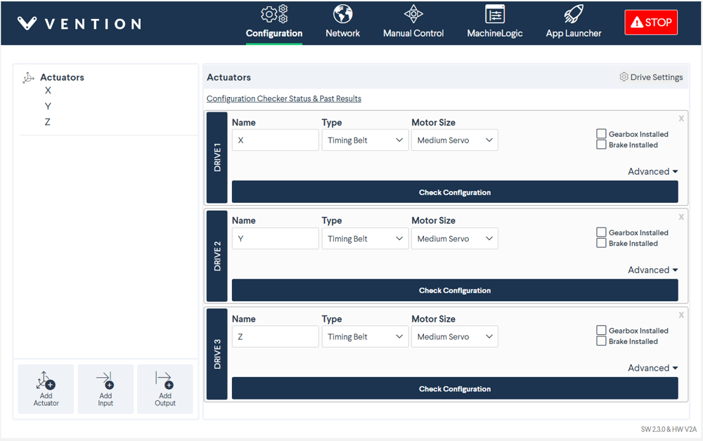
The configuration parameters of each actuator can be changed independently as seen in the figure above. The initial page will appear blank. To configure an actuator, click Add Actuator at the bottom left-hand corner. You could add up to four drives. To configure a digital input/output device, click Add Input/Output.
Enter all fields to each drive:
- Name: Friendly name given to the actuator
- Type: The actuator type. Select based on your machine design.
- Motor Direction: Rotation direction, see Motor Rotation Direction below.
- Gearbox installed: If you have a gearbox installed on the actuator, check “Gearbox Installed”
- Brake installed: If you have a power-off brake installed on the actuator, check “Brake Installed”
- Motor size: Select the motor size associated with the actuator. The drop-down menu has three options (small servo (68 mm), medium servo (100 mm) and large servo (157 mm)). If an electric cylinder is selected as the actuator type, only the Nema 17 stepper option will be available.
- Motor current: Specify the current to power the servo-motor with. See table below for current rating of each servo- motor.
- Micro steps: This is an advanced feature if more precision is required. The micro steps should be left at 8 (default). Select based on your machine design support for high precision applications.
- Tuning profile: This allows you to tune your step-servo motor using various profiles, to achieve the best performance for your application. Note that the tuning profile is only configurable in a closed-loop setting.
Enter all fields for each IO device:
- Name: Friendly name given to each input/output device
- IO Type: To determine if the device is an input or output device
- Device: Represents the device ID of your digital IO module. Select between 1 to 3, depending on what is written on the nameplate of the digital IO module.
- Pin: Represents the number of the digital IO module pin you have connected your input/output device to. Select between 0 to 3, depending on where you have plugged your device. Please be careful: if the digital IO module faceplate numbers them from 1 to 4, your configuration and your programs (MachineLogic or Python) numbers them from 0 to 3. Therefore, input pin 1 as written on the faceplate of the IO-Expander corresponds to input pin 0 in the Control Center and MachineLogic.
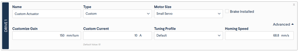
Custom Actuator Tuning:
For some application, it may be required to configure custom actuators. This can be the case when using actuators from external vendors, or when wishing to exceed speeds of 50mm/s with Enclosed Ball Screw Actuators or Enclosed Lead Screw Actuators. Critical speeds for these actuators can be found in the linked data sheet.
To configure custom actuators, simply select Custom in the Type drop-down menu and specify your own values for Gain and Current. Call Vention Support if further assistance is required.
Actuator Hardware Configuration
Motor Rotation Direction
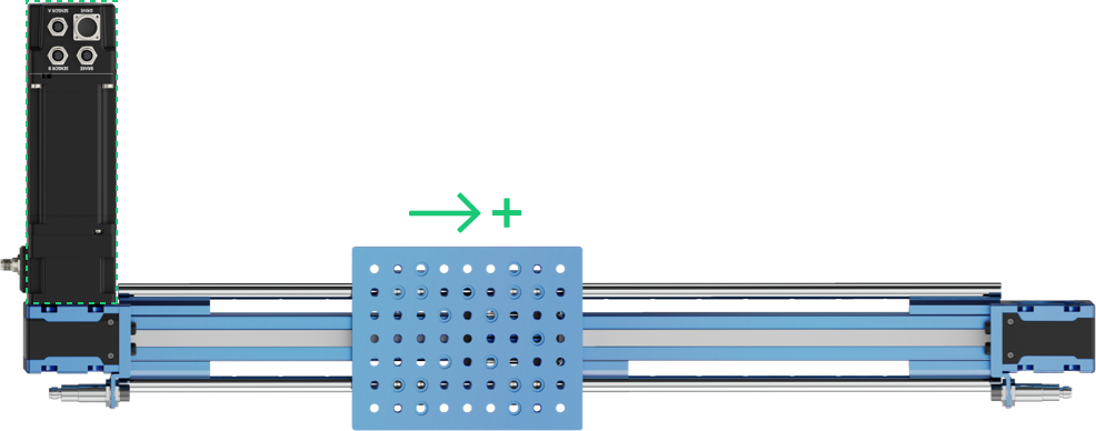
By convention, motors have a reverse and a normal rotation direction. This is an important consideration when installing the motor on an actuator. When sending motion commands to the controller (for example a relative move of +200 mm), it is important that the actuator moves in the desired direction. See figures below for motor rotations; the figures show the side of the output shaft.
![]()
![]()
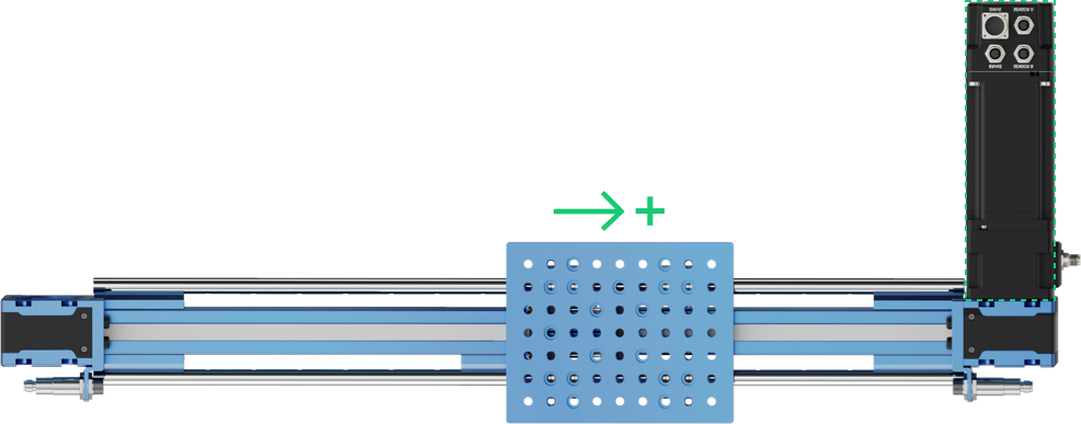
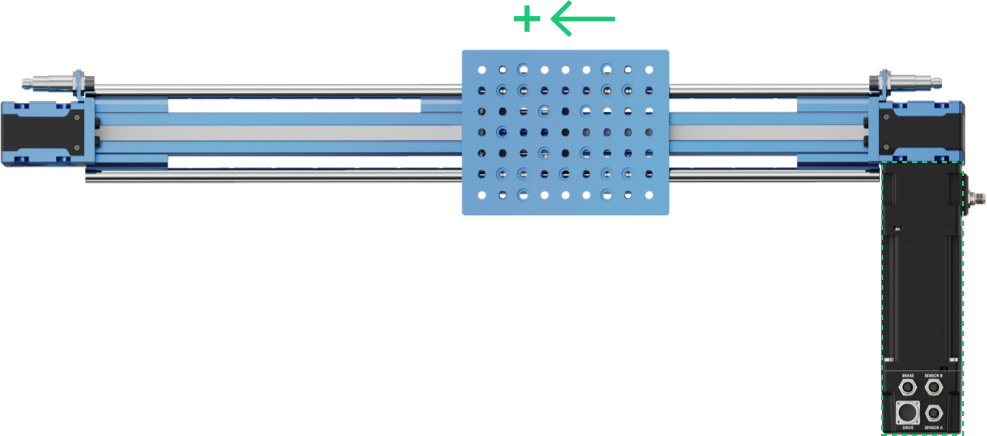
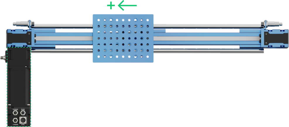
Linear Actuator Direction
In order to satisfy the application requirements, ensure the installed positioning on the step-servo motor has the intended positive direction. The figure below shows how the linear actuator moves depending on where the motor is installed.
End-stop Sensors
Linear actuators require end-stop sensors for two reasons:
- To perform homing operations (placing the actuator in a known position, called home or zero) on the actuator. This allows the actuator to zero its position to initialize its position.
- To disable motion in the event of over- or under-travel. Over- or under-travel occurs when the gantry travels beyond the limits of an actuator.
Inductive sensors are the preferred option for end-stop sensors since they are non-contact and less subject to environmental interference:
- M18 Inductive Proximity Sensor (Sn = 10 mm): CE-SN-004-0001
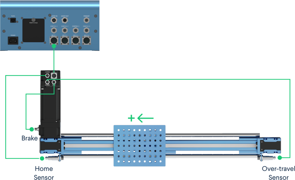
The image below details how to connect and position the end-stop sensors for a specific motor position. Important points:
- The home sensor is positioned such that a negative motion moves towards it
- The home sensor is connected to port SENSOR A on the motor junction box
- The over-travel sensor is positioned such that a positive motion moves towards it
- The over-travel sensor is connected to port SENSOR B on the motor junction box

Direction Reversal
It is possible that for design reasons, the motor has to be placed at a specific place on the linear actuator (due to space or mechanical constraints). This could result in an undesired positive motion direction of the linear actuator. For this reason, there is also a software command that permits reversing the direction of a given actuator. The Configuration tab contains a software command that allows you to reverse motor direction, as shown below:

This configuration reverses the motor default rotation direction, but also reverses the position of the home and over-travel sensors.
Reversing the motor direction results in the following configuration:
- The home sensor is positioned such that a negative motion moves towards it
- The home sensor is connected to port SENSORB on the motor junction box
- The over-travel sensor is positioned such that a positive motion moves towards it
- The over-travel sensor is connected to port SENSORA on the motor junction box
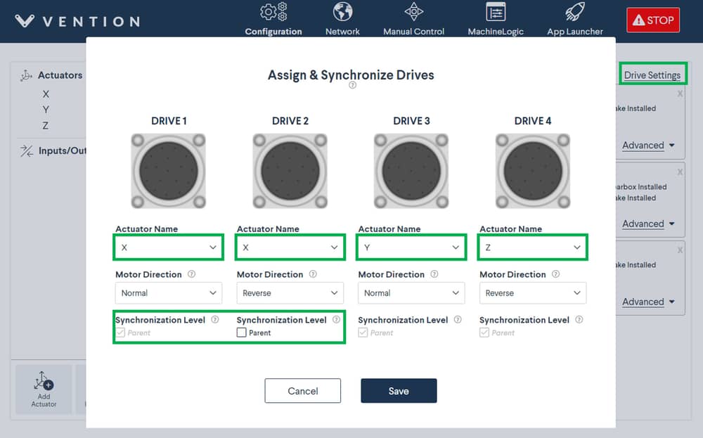
Synchronize drives
Using the Drive settings in the configuration tab will also allow you to synchronize drives together. Drives can only be synchronized if the actuator type, gearbox setting, brake setting, motor current, and motor sizes are the same. Follow the steps below to synchronize drives together:
- Go to the configuration tab
- Click “Add Actuator” and configure the actuator.
- Click “Drive settings” and in the “Actuator Name” drop-down, you can select the same actuator name in multiple drives to synchronize the motors.
Parent synchronization level means that the motor has the home and end sensor connected. The child drive should not have any home or end sensors (only jumper sensors connected into the sensor ports).
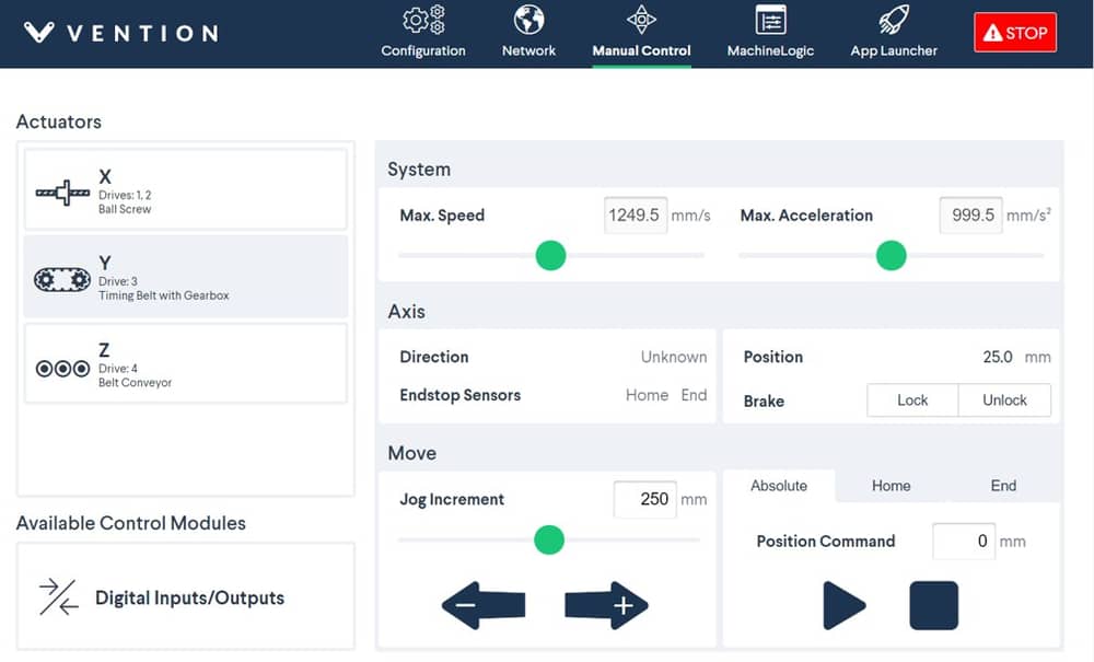
Testing your set-up using Control Center
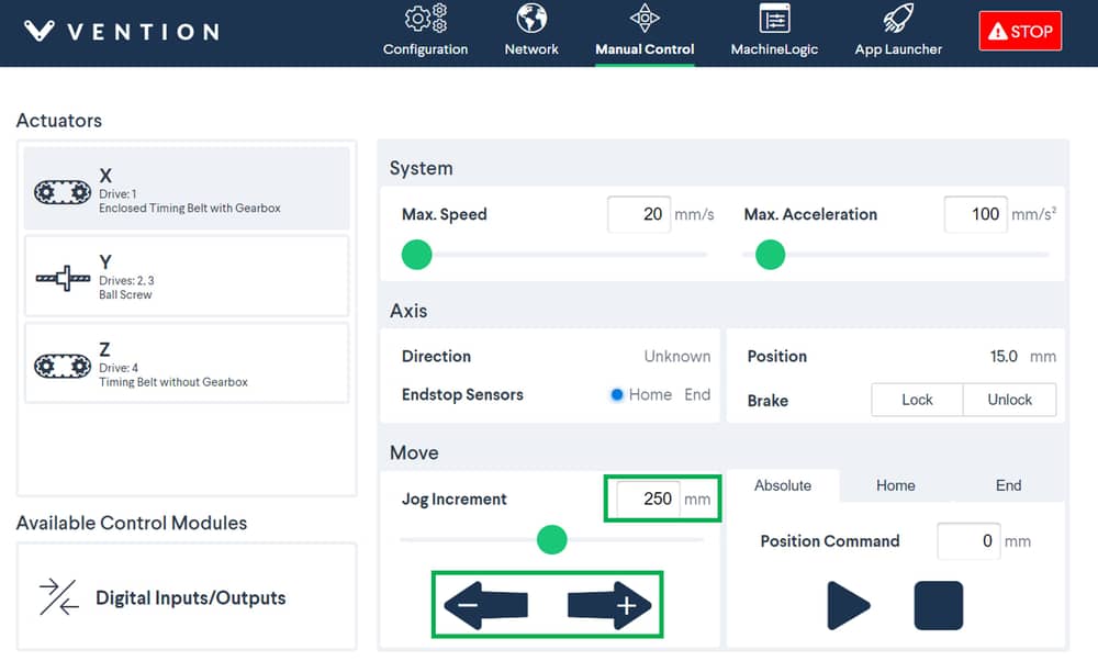
After configuring your actuators and setting up your hardware, we recommend testing your automated equipment using the Manual Control tab.
STEP 1: Click Manual Control (underlined in green, the tab at the top of the screen).
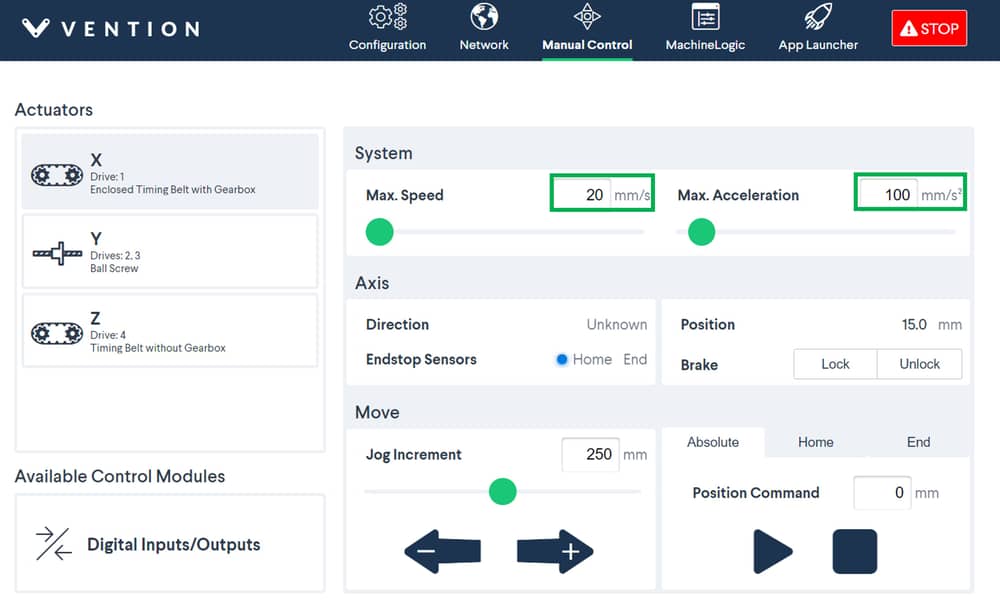
STEP 2: Set a relatively low speed (recommended: 20 mm/sec) under the field Max. Speed and a low acceleration (recommended: 100-150 mm/s) under the field “Max. Acceleration” for testing purposes.
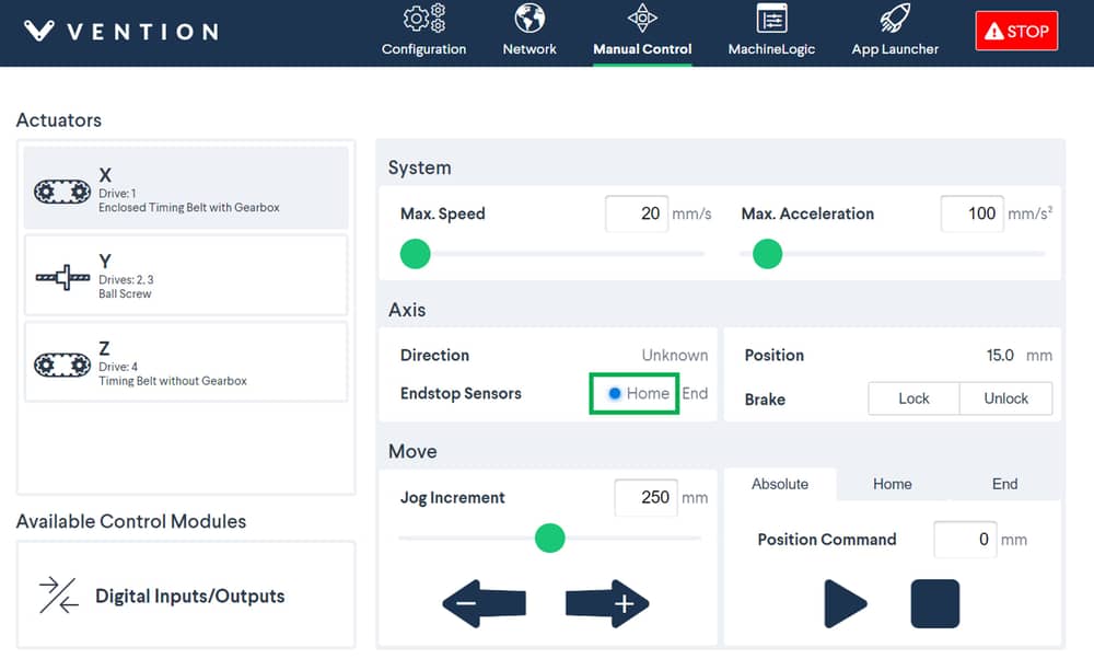
STEP 3: Test the functionality of your end-stop sensors to ensure they are properly connected. Place a metal object (like a fastener or house key) in front of your home and end sensors. If properly connected, the “Home” and “End” circles should turn blue. See the figure below as a reference for when the home sensor is triggered.
STEP 4: Jog your actuator at a set increment to ensure the motor is properly connected. Enter the increment at which you would like to jog your actuator (recommended: 50 mm). Click the left or right arrow to jog your actuator in that increment. Your actuator should move in that increment every time you press the left or right arrow.
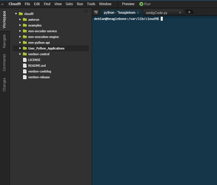
Cloud9 Integrated Development Environment
For users that desire to access the single-board computer that is located inside the controller, the Cloud9 IDE is available on port 3000.
Cloud9 offers a terminal access and file explorer for developing software directly on the MachineMotion controller.
To access Cloud9, browse to 192.168.7.2:3000 or <your_custom_machine_motion_ip>:3000. The username is debian and the password is the one you set when first installing your MachineMotion.
MachineLogic
MachineLogic is the preferred option for programming within the Vention ecosystem. It contains both a code-free interface and a Python IDE, providing a path to quick and simple automation programming for users of all skill levels. click here to access MachineLogic’s resource center.
MachineLogic Code-Free Programming
MachineLogic’s Code-Free programming lets users program using simple instruction cards in a drag and drop, code-free interface. Click here to learn more about code-free programming. For robot specific applications, click here.
MachineLogic Python Programing
MachineLogic Python Programming lets users program application using well-known and documented Python syntax. Click here to access the Python documentation