

User manual
Updated: Thursday, January 18th 2024
Latching Pushbutton Module User Manual
Contents
- Overview
- Features
- Included in the Box
- Physical Interface
- Status LED Indicators
- Applications
- Setting the address configuration switches
- Configuring the Latching Push-button Module in Control Center
- Programming the Latching Push-button Module with MachineLogic
- Using the Smart Push-button with the Python API
Overview
The Latching Pushbutton Module, CE-MD-004-0000, extends MachineMotion 2’s functionality with two latching (alternate action) pushbuttons. This plug-and-play module only requires a single connection to the MachineMotion 2 controller. Compatible modules, such as the Smart Power Switch (CE-MD-005-0000) & additional Pushbutton modules can also be daisy chained to each other, making it possible to connect up to eight modules per MachineMotion 2 controller.
Features
- Includes two latching pushbuttons
- Connects (daisy chain) with compatible modules
- Configurable address
- Plug-and-play access from the Control Center, MachineLogic, and Python API
Included in the Box
| Part Number | Description | Quantity |
|---|---|---|
| CE-MD-004-0000 | Latching Pushbutton Module | 1 |
| CE-CA-022-5000 | Control Device Extension Cable, 5m | 1 |
| CE-JP-001-0001 | Module Termination Jumper | 1 |
| HW-FN-003-0018 | M8 x 18-mm Screw | 2 |
| HW-FN-002-0001 | M8 Drop-in Spring-Loaded T-Nut | 2 |
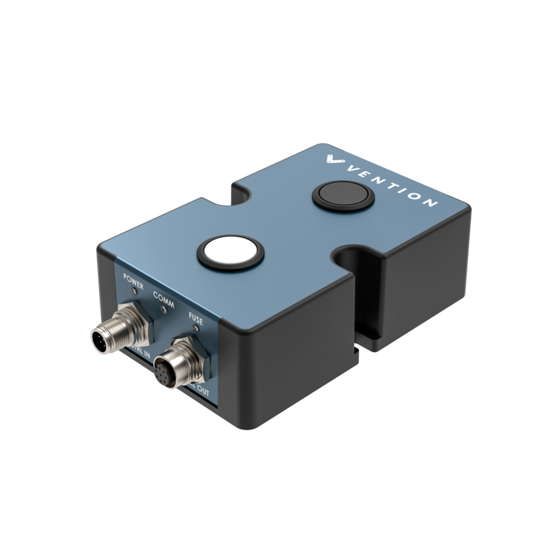
Physical Interface
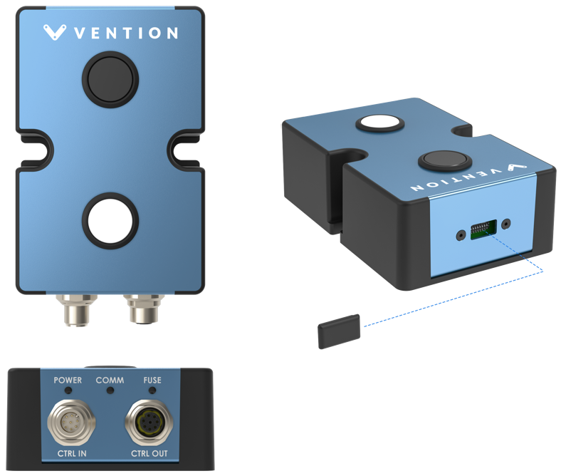
Status LED Indicators
| Name | LED Color | Indicated (when ON) |
|---|---|---|
| POWER | White | 24 VDC supplied to module |
| COMM | Yellow and Blue | RS-485 communication functional |
| FUSE | Red | Module internal fuse tripped |
Applications
Connecting to MachineMotion 2 (directly)
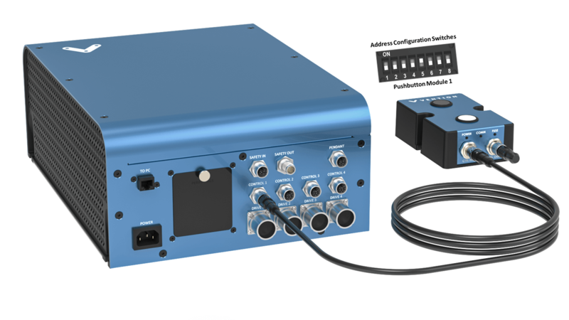
To connect a Pushbutton Module directly to MachineMotion 2 (see Figure 2):
- Set the address of the Pushbutton Module, as explained in the Setting the address configuration switches section below.
- Using the Control Device Extension Cable (CE-CA-022-5000):
- Connect the male end to any CONTROL port on MachineMotion 2.
- Connect the female end to the CTRL IN port on the Pushbutton Module.
- Connect the Module Termination Jumper (CE-JP-001-0001), to the CTRL OUT port on the Pushbutton Module.
Connecting to MachineMotion 2 (daisy chain)
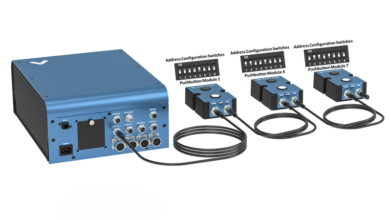
Compatible modules, including the Latching Pushbutton Module, can also be connected via daisy chain to a single CONTROL port on the MachineMotion 2 controller (see Figure 3). Across all four CONTROL ports, the controller supports up to eight modules at the same time, provided they all have distinct addresses (see Address configuration switches).
To connect several modules in a daisy chain:
- Set a distinct address for every module of the daisy chain, as explained in the section Setting the address configuration switches.
- Using a Control Device Extension Cable (CE-CA-022-5000):
- Connect the male end to any CONTROL port on MachineMotion 2.
- Connect the female end to the CTRL IN port on the first module of the daisy chain.
- For every additional module to be connected in the daisy chain, repeat this step using an additional Control Device Extension Cable (CE-CA-022-5000):
- Connect the male end to the CTRL OUT port on the previous module in the daisy chain.
- Connect the female end to the CTRL IN port on the current module in the daisy chain.
- Connect the Module Termination Jumper (CE-JP-001-0001), to the CTRL OUT port on the last module in the daisy chain.
Setting the address configuration switches
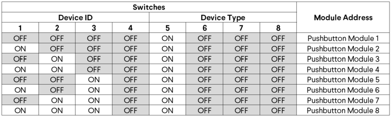
Each module has an address with two components: device ID and device type. Both device ID and device type are set by changing the state of the address configuration switches, which are located at the back of the Pushbutton Module under a removable rubber cap.
Switches 1 to 4 define the module device ID and allow the MachineMotion 2 controller to know which module it is communicating with. Every module connected to the same controller should have a distinct device ID, regardless of its device type.
Switches 5 to 8 define the module device type and their positions should remain identical for all modules of the same type.
The table below lists every valid address for the Pushbutton Module. An individual switch is considered ON when the selector is slid up and OFF when the selector is slid down.
Configuring the Latching Push-button Module in Control Center
If you would like to configure your Latching push-button and utilize MachineLogic to program your push-button, follow the steps below:
- Open the Control Center on a PC (by entering 192.168.7.2 in the Google Chrome URL) or use the MachineMotion 2 Pendant.
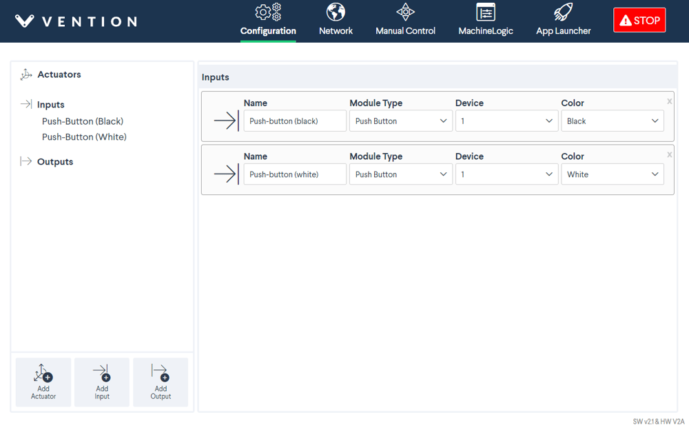
- Go to the Configuration tab and click Add Input.
- Fill out the following fields:
- Name: Give your push-button a friendly name, which will be used to call the push button module in MachineLogic
- Module Type: In the drop-down menu, select Push Button
- Device: Represents the device ID of your module. The device number is configured on the physical module using dip-switches, therefore, ensure the device ID configured in this dropdown matches the dip switches configured on the physical device.
- Color: Select the push-button color you would like to configure.
- To test the configured push-buttons, go to the Manual Control tab and navigate to the Digital Inputs/Outputs at the bottom left of the screen.
- Under Inputs, you should see your configured push-button modules:
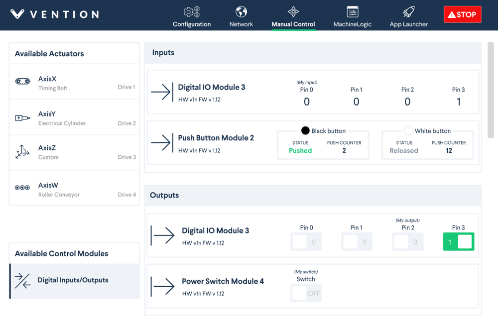
You could see the status of each button as “Pushed” or “Released”. The push counter allows you to test the push buttons in case the push button is installed far away from your HMI. The counter will go up each time the button is pressed.
Programming the Latching Push-button Module with MachineLogic
To program your Latching push-button in MachineLogic, ensure you have completed the steps in Configuring the Latching Push-button Module in Control Center.
- Go to the MachineLogic tab.
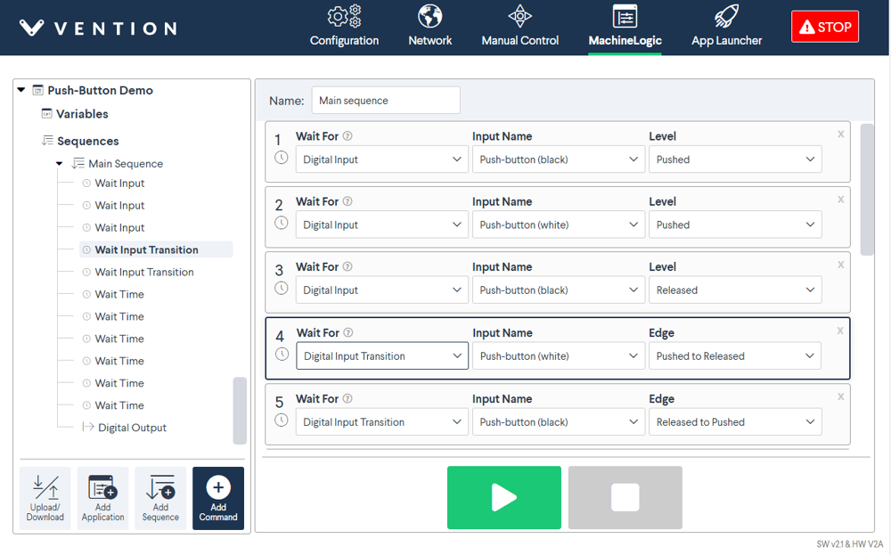
- There are a few commands that could be used for your push-button module. Click Add command > Add Wait:
- Under Wait For, selecting Digital Input would allow your program to wait for a push button to be Pushed or Released before playing the next command
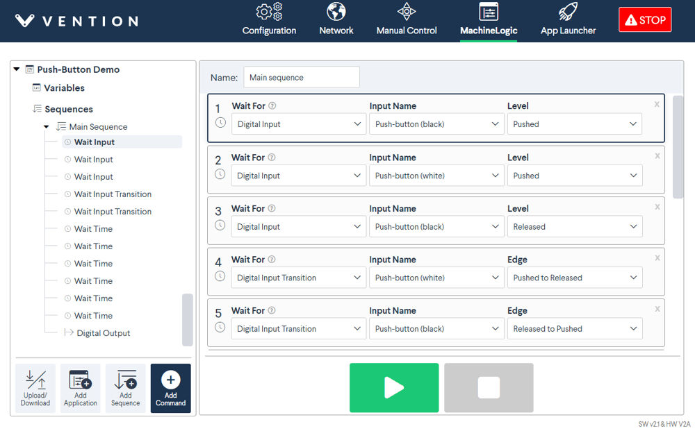
- Under Wait For, selecting Digital Input Transition would allow your program to wait for a push button to go from one state (pushed/released) to a different state (pushed/released) before playing the next command.
Using the Smart Push-button with the Python API
See Python API reference here