247.5 mm Extrusion Ecosystem Tech Doc
Introduction to 247.5 mm Ecosystem
The 247.5 mm ecosystem has been designed to cover heavy-duty applications. This XL ecosystem can effectively reduce the complexity and the number of parts in heavy-duty structures which used to be designed using smaller extrusions such as 45x45, 45x90, and 90x90 mm profiles.
This document will outline the extrusion’s capabilities, recommended configurations, handling procedures, and limitations that must be respected.
Applications
The 247.5 mm ecosystem is ideal for multiple types or large structures. One example is replacement of lattice frame X axes is large cartesian applications like the following.
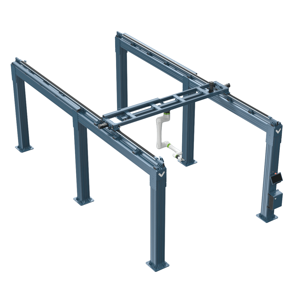
This greatly reduces the number of extrusions required and also makes the structure much more rigid.
Another application example that the 247.5mm ecosystem is well suited for is overhead robot range extender frames.
Supporting Architecture
Here is the list of the new parts in this ecosystem as well as supporting parts that can be used together to create structures for your applications.
New parts:
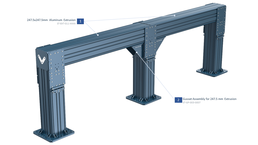
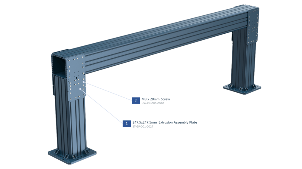
- 247.5 x 247.5 mm Extrusion (ST-EXT-011-XXXX):

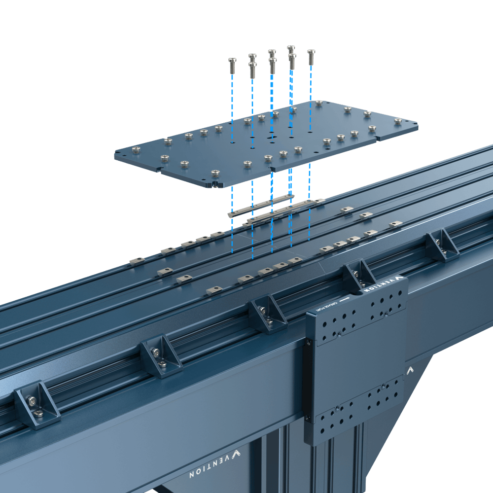
- 247.5 x 247.5 mm Extrusion Assembly Plate (ST-GP-001-0027):
This plate is used for connecting XL extrusions to each other.

- Large Extrusion Leveling Fixture (ST-SP-016-0001):
This fixture is used for leveling 247.5 mm extrusion structures.

- Floor Anchor for 247.5 mm Extrusions (ST-SE-001-0008):

- 247.5 X 247.5 mm Extrusion Endcap (HW-EC-011-0001):

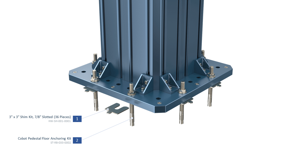
- 3” x 3” Shim Kit (HW-SH-001-0001):
For shimming the floor anchor plate.
![]()
Supporting parts:
- Actuator Mounting Plate (ST-GP-005-0010):
This plate is used for mounting Vention linear actuators on XL extrusions.

- Gusset Assembly for 247.5 mm Extrusion (ST-GP-003-0007):
This gusset is made of 2x ST-GP-005-0010 and 2x ST-GP-005-0012 plates and is used in the joints of XL extrusion structures.

- Floor Anchoring Kit (ST-RB-033-0002):
For anchoring the floor anchor plate.

Structural Joint Design Guide
This section covers common types of connections used in the XL ecosystem along with a qualitative look at rigidity. It should be noted that in all cases below the limitation of the connection is the friction capacity of the joint and not the extrusion.
Note: Make sure the tightening torque for M8 screws in XL ecosystem is between 10 and 13 N.m.
Fully Supported Structure (Bending Load)
- A fully supported structure can be made by using 4 Assembly Plates for connecting a beam to two columns.
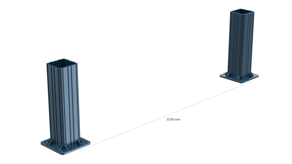
- The maximum allowable load (F) is 5 kN for a 3330 mm span in the above configuration, which needs to be considered in your design.
- In the calculation of the force (F), Static and Dynamic effects need to be considered.
| Config type | |
|---|---|
| Config Name | 3330 mm span frame with 2 Assembly Plates at each side |
| Max Force (N) | 5000 |
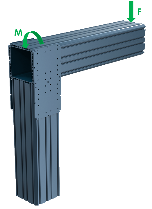
Cantilevered Structure (Bending Load)
- In a cantilevered bending structure, there are 3 recommended joint configurations which can be seen in the table below. The maximum allowable bending moment (M) due to the force (F) shown in the pictures needs to be considered in your design according to the table.
- In the calculation of the force (F) and moment (M), Static and Dynamic effects need to be considered.
- The order in the table is from high rigid config to less rigid config.
| Config type | 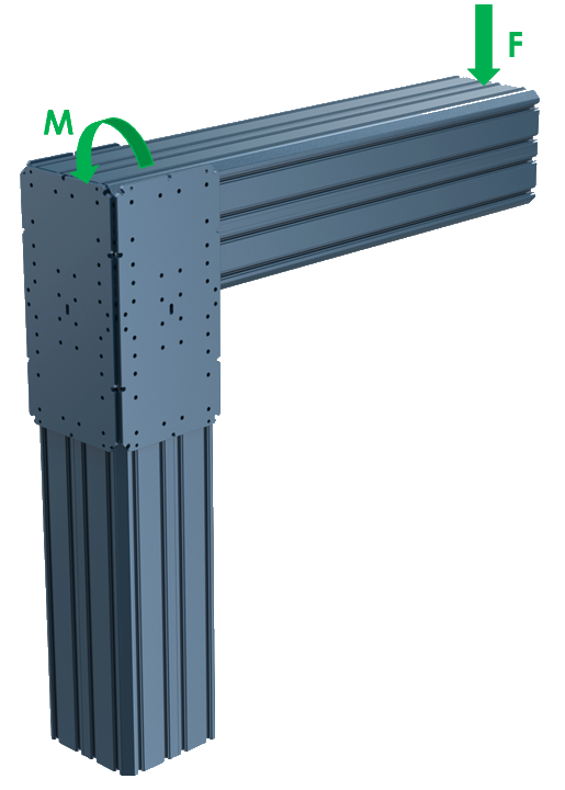 |
 |
 |
|---|---|---|---|
| Config Name | 3 Assembly Plates | 1 Assembly Plate at the end and 1 big gusset | 2 Assembly Plates at the sides |
| Max Moment (N.m) | 1250 | 1250 | 1250 |
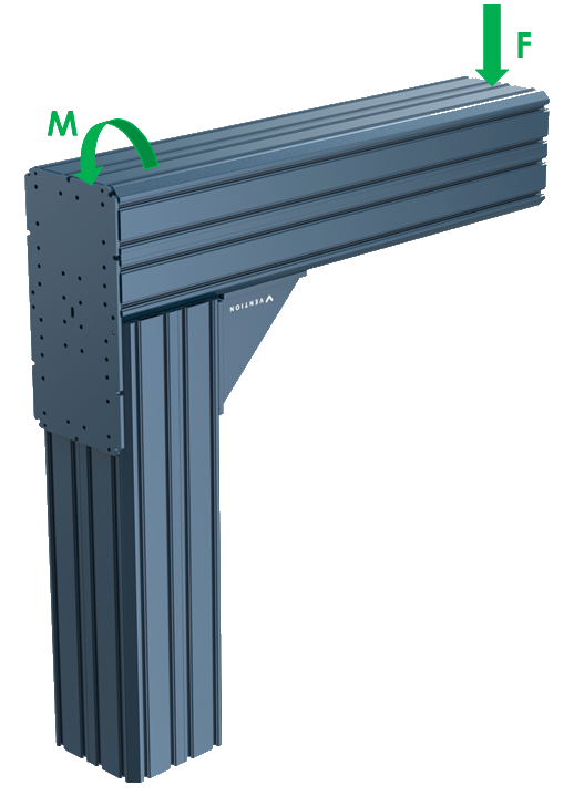
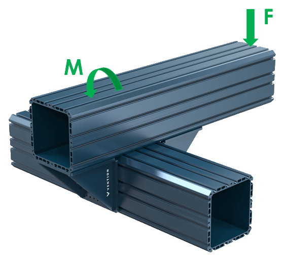
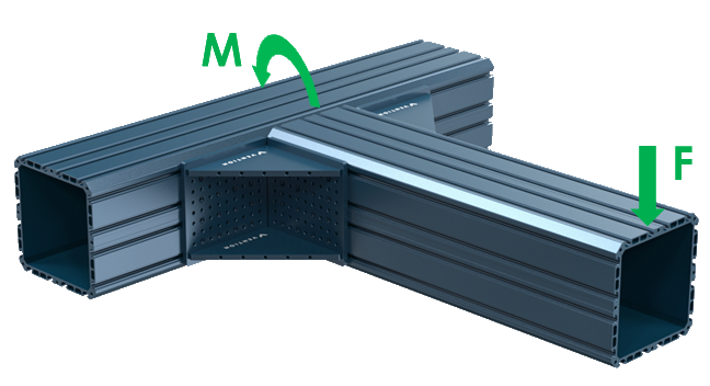
Cantilevered Structure (Torsion Load)
- In a cantilevered torsion structure, there are 3 recommended joint configurations which can be seen in the picture and table below. The maximum allowable bending moment (M) due to the force (F) shown in the pictures needs to be considered in your design according to the table.
- In the calculation of the force (F) and moment (M), Static and Dynamic effects need to be considered.
| Config type | 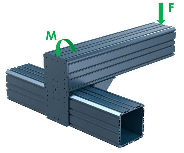 |
 |
 |
|---|---|---|---|
| Config Name | 1 gusset at the bottom and 1 Assembly Plate at the end | 2 gussets at the bottom side | 2 gussets at the sides |
| Max Moment (N.m) | 1250 | 1250 | 1250 |
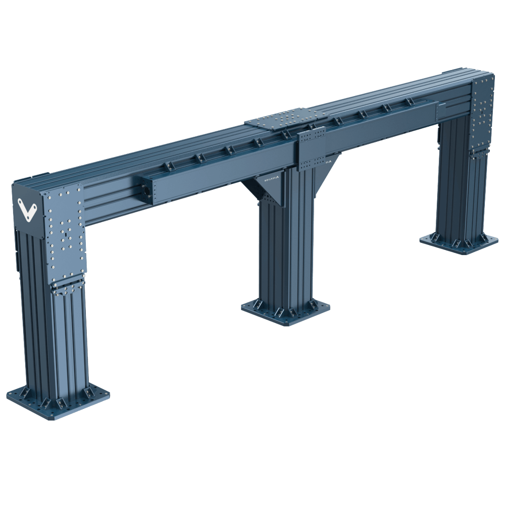
Long Structures
By attaching two XL beams to each other, you can create longer structures, but make sure you have a column right beneath the joint like in the picture below.
Additionally, it is suggested to use the long Butt-Joint Extrusion Connectors so improve the strength of the joint. The following image shows how they can be used.
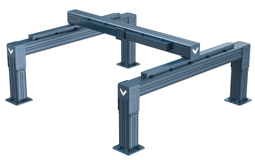
Gantry Structure
Gantry structures can be made using the 247.5 mm ecosystem using 2 parallel frames made of XL extrusions beside each other and 1 beam in between.
Note: Special attention must be given to the alignment of the parallel structures. Use of high precision bearing systems rigidly mounted in a parallel configuration requires horizontal positional tolerances of 0.025mm or 0.001”. Height tolerances are also important but are much less tight. For additional information on alignment requirements reach out to our Application Engineering team.
One method of aligning these structures is the use of high precision laser measurement devices that have accuracies within the positional tolerance range mentioned above.
Another simple but practical method is to create an assembly gauge to use as a spacer between each set of vertical posts. This method will allow for consistent width spacing of the vertical posts by temporarily rigidly connecting the two sides of the gantry structure during construction.
- Assemble one side of the gantry as per the instructions at the end of this document.
- Once one side is fully installed and anchored in place, the construction of the second side of the gantry system can begin.
- Use the gauge (extrusion of specific length) to space the first column of the second side. The gauge should be attached firmly to both the first and second side so that they are pulled to the exact width of the gauge. Anchor this first column.
- Repeat step 3 for each column on the second side. Anchoring after each spacing. Using the gauge ensures that all column pairs are spaced at the exact same distance from each other and will allow for a much more successful alignment process.
Floor Anchor Limitations
When designing a frame with the XL extrusions, it is important to keep the limitations of the anchors in mind. The customer is responsible for a complete assessment of the concrete where the structure will be installed to ensure it will be able to take the loads transferred from the frame.
The floor anchors have a maximum amount of moment load that they can support which is limited by the bolted connection between the anchor and the extrusion.
See the table below:
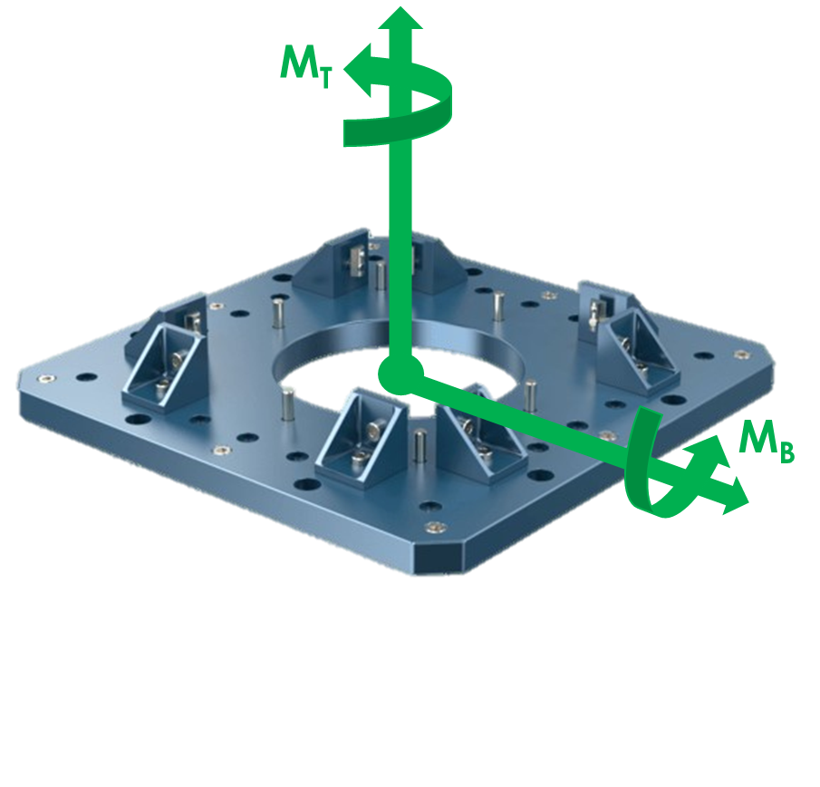
| Direction | Max Moment [Nm] |
|---|---|
| Mb (Bending Moment) | 2000 |
| Mt (Twisting Moment) | 1750 |
How to Mount Vention Actuators on 247.5 mm Extrusions
In this section, the installation of different types of Vention linear actuators will be explained.
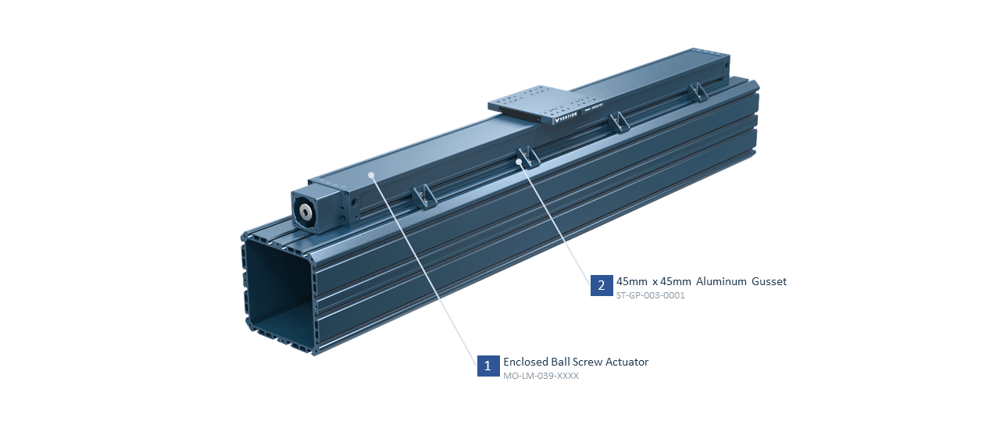
Ball Screw
When installing Vention Enclosed Ball Screw and Lead Screw actuators on XL extrusions, 45 x45 mm Vention gussets (ST-HP-003-0001 and ST-GP-003-0001) can be used like the picture below.
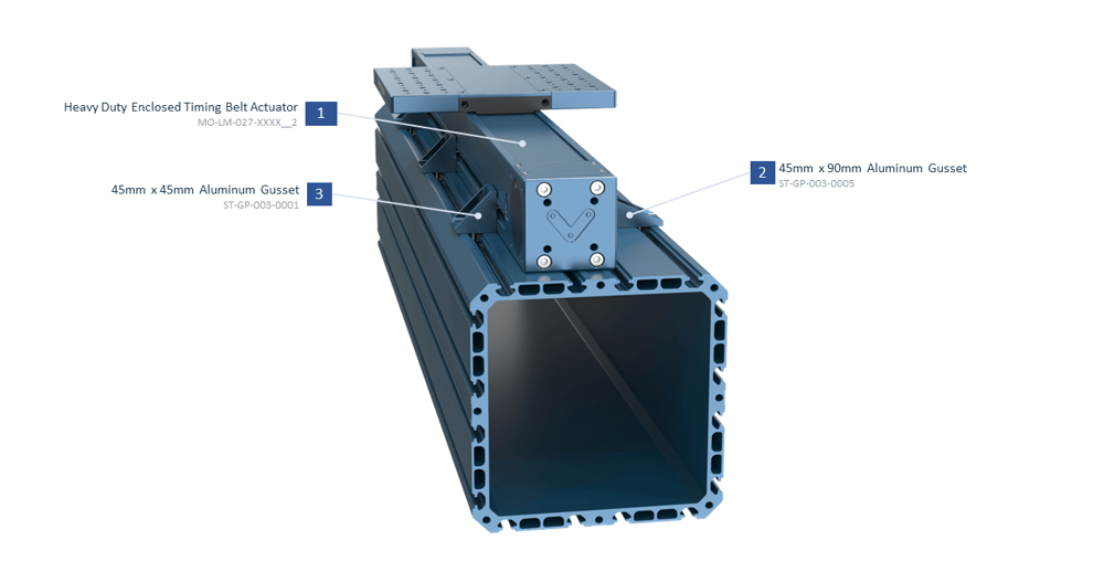
Enclosed Timing Belt
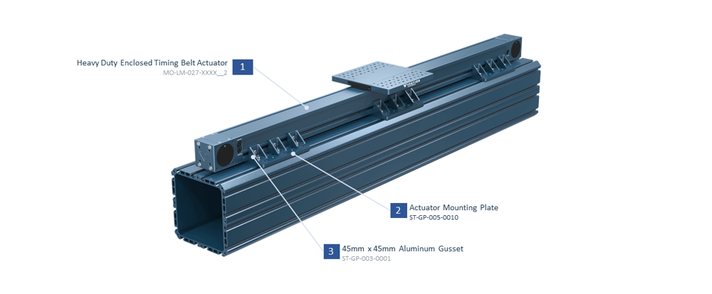
- When Installing Vention Enclosed Timing Belt Actuators centered on the XL extrusions, Actuator Mounting Plate (ST-GP-005-0010) can be used. First, install several Actuator Mounting plates on the 247.5 mm extrusion and then the Enclosed Timing Belt actuator will be installed on these Mounting Plates using Vention gussets like the picture below.
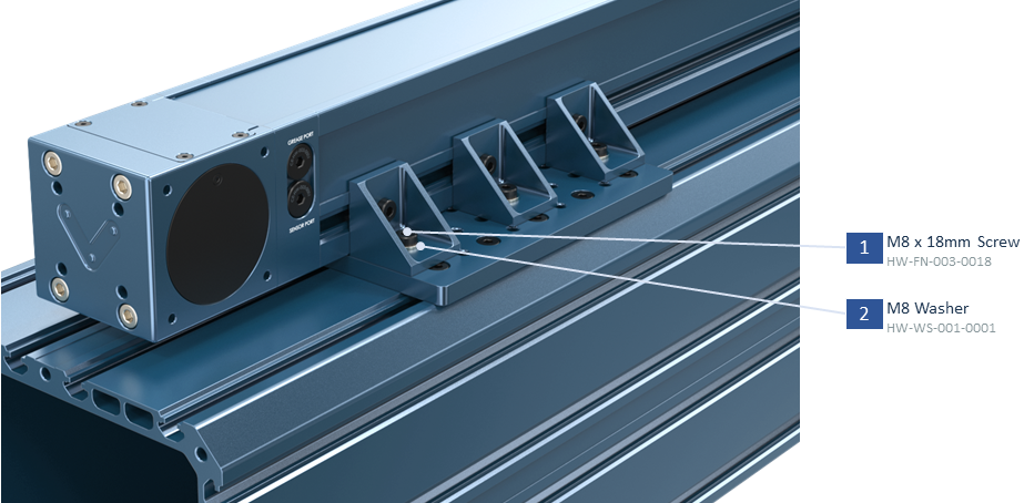
Important Note: When connecting an actuator to the XL extrusion system via the Actuator Mounting Plate ST-GP-005-0010 (ST-GP-005-0010), you need to use washers (HW-WS-001-0001). These can be added as add-ons in Machine Builder. (see the picture below)
- Alternatively, an enclosed timing belt can be mounted off-center by using 45x45 mm gussets (ST-GP-003-0001) in combination with 45x90 mm gussets (ST-GP-003-0005). No additional mounting plates are needed in this configuration.
45x90 Based Actuators
Actuators that are intended to be mounted on standard 45x90 mm extrusions such as rack and pinion, open timing belt, and the belt rack actuators can be mounted on XL ecosystem by mounting the 45x90 mm gussets to the 247.5 mm extrusion.
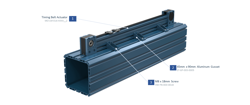
All these actuators can be mounted centered on the XL extrusion by using ST-GP-003-0005 gussets.
Assembly Instructions and Installation Procedure
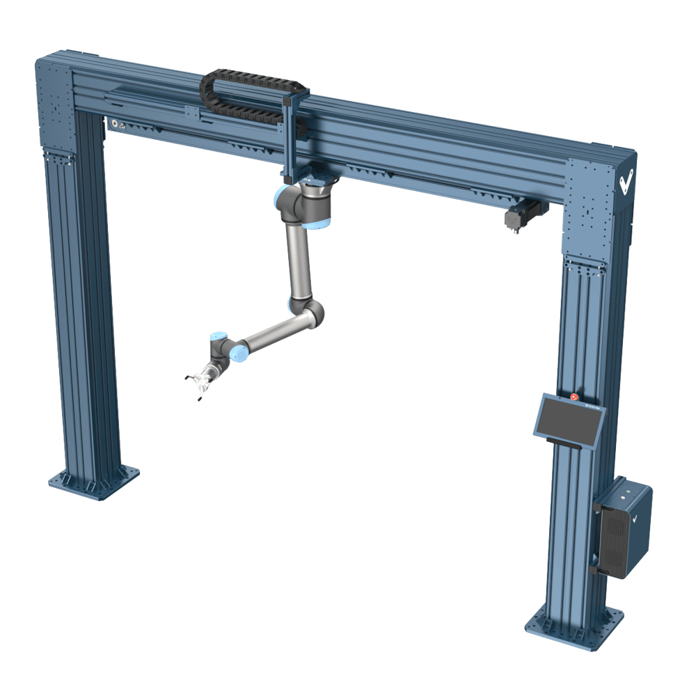
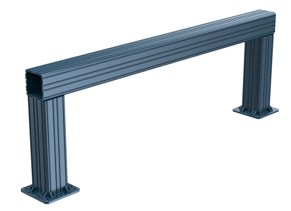
This section contains a step-by-step guide for building a structure like the picture below using 247.5mm extrusions and other XL ecosystem parts.
General note: unless otherwise specified, any bolt that connects to the t-slot of a 247.5mm extrusion should be torqued to 10-13Nm.

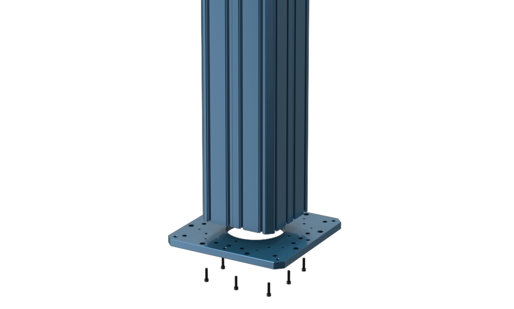
1. Install the XL column (ST-EXT-011-XXXX) on the reinforced base plate (ST-SE-001-0007) of the Floor Anchor Assembly (ST-SE-001-0008) using 8x M8x35 mm (HW-FN-003-1035). These bolts should be torqued to 25-30 Nm. We recommend adding Loctite to these fasteners.
2. Install the gussets and M14 set screws (jack screws) according to the picture below.
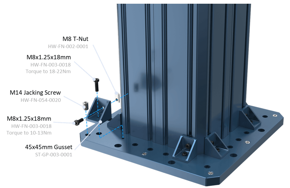
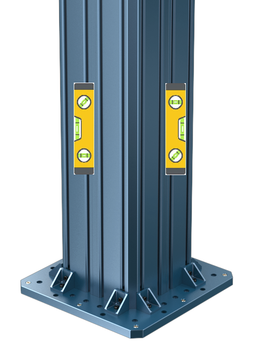
3. Check if the above assembly is perpendicular to the floor using a level by Placing it on 2 sides of the column. If the column is not level, use 8x M14 set screws (HW-FN-054-0020) on the plate to level it.
4. Once the column is level and in the correct location, use the shim kit (HW-SH-001-0001) to fill the gap between the plate and the floor. Install the shims and anchor bolts in the shown location according to the picture below. The shim slot should hug the anchor bolt. Use 8x 1/2 inch anchor bolts from the anchoring kit (ST-RB-033-0002) to anchor the plate to the floor. The holes can be drilled in concrete using a hammer drill.
5. After anchoring the first column in your preferred location, place the other column from a 3330 mm distance from the above one. (the distance depends on the beam length).
6. Place the 3330 mm horizontal beam on top of these 2 columns. For lifting the beam, you can use one of the methods explained in the Recommended Handling Methods section at the bottom of this page.
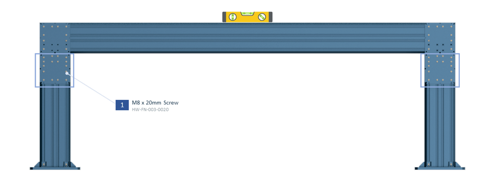
7. Install 4 assembly plates for connecting to the horizontal beam as in the picture below. To align the second column, temporarily tighten all M8x20 mm screws of assembly plates with a torque wrench (10-13 Nm). Make sure both ends of the horizontal beam are tangent to the columns’ outer sides. Tightening the bolts will pull the assembly straight.
8. Now that we are sure that the second column is in its exact right location, you need to loosen the above screws of the Assembly Plates of the second installed column and redo steps 2, 3, 4, and 5 for this column too.
9. Now it’s time to level the horizontal beam. Place a level on top of the horizontal beam. If it’s not level, loosen the bolts (shown bolts in the square outlines below) that attach the assembly plate, ST-GP-001-0027, to the vertical column so that it can slide vertically.
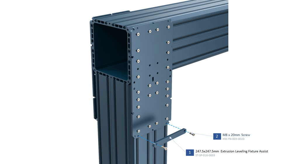
10. Now it’s time to install the leveling mechanism. First, install the ST-SP-016-0003 on Assembly Plate with 2x M8x20 mm like in the picture below.
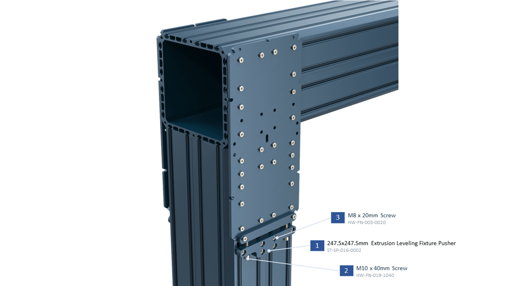
11. Install ST-SP-016-0002 by tightening the shown 6x M8x20 mm screws. Then using 2x M10x40 mm you can move the assembly plate up and down and level the horizontal beam. Install one leveling mechanism for each assembly plate on both sides of the column.
12. After leveling the horizontal beam, you can tighten all the screws of the assembly plates shown in step 9.
13. Install the End Cap (HW-EC-011-0001) to close the beam end using 4x M8x10 mm (HW-FN-003-0010) screws.
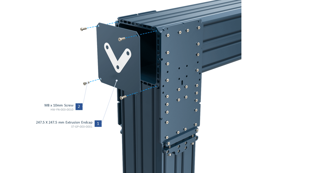
Note: Use High Strength Thread Locker (HW-CS-001-0003) to prevent the screws from loosening over time due to vibration.

Recommended Handling Methods of 247.5 mm Extrusions
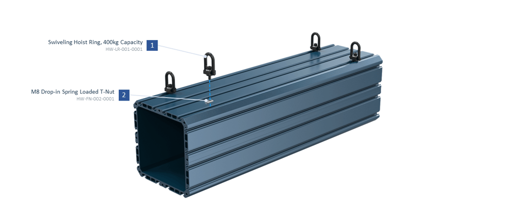
- In case you have access to a crane, you can install 4 swiveling hoist rings (HW-LR-001-0001) on 4 corners of the extrusion as in the picture below. First, insert 4x M8 T-nuts (HW-FN-002-0001) inside the shown grooves of the extrusion and tighten the M8 screws of the Hoist Rings. Now you can use straps to connect the 4 Hoist Rings to the hook of your crane.
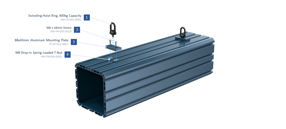
- Another option using hoist rings would be to center two of them on the extrusion using the mounting plate ST-SP-012-0001 like shown:
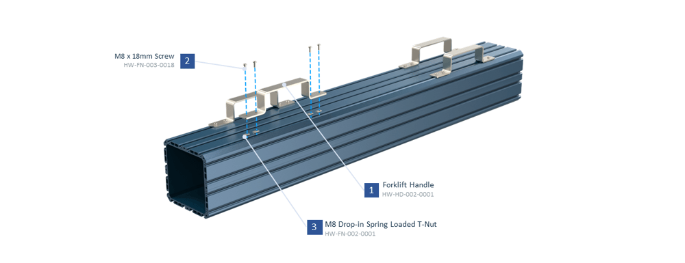
- In case you have access to a forklift, you can install 4 forklift handles (HW-HD-002-0001) on top of the extrusion, and it can easily be lifted by the forklift. Each forklift handle is installed on the extrusion using 4x M8 T-nuts (HW-FN-002-0001) and 4x M8 screws (HW-FN-003-0018) as in the picture below. The tightening torque for M8 screws is between 10 and 13 N.m.
- Finally, you may also hoist the extrusion using a long strap passed through the center of the extrusion profile, however, this may not be possible if you are in the process of butt joining two extrusions as the ends must be available for this technique… etc.