Introduction to Vention’s Sliding Door Hardware
Sliding doors in industrial applications offer several advantages over traditional hinged doors that cannot be overlooked when seeking to optimize your workstation. The benefits include space optimization, easy access to machinery, user safety, maintenance access, division of workspaces, etc.
Vention’s ecosystem includes two types of sliding door: panel sliding doors and extrusion frame sliding doors.
Panel Sliding Door
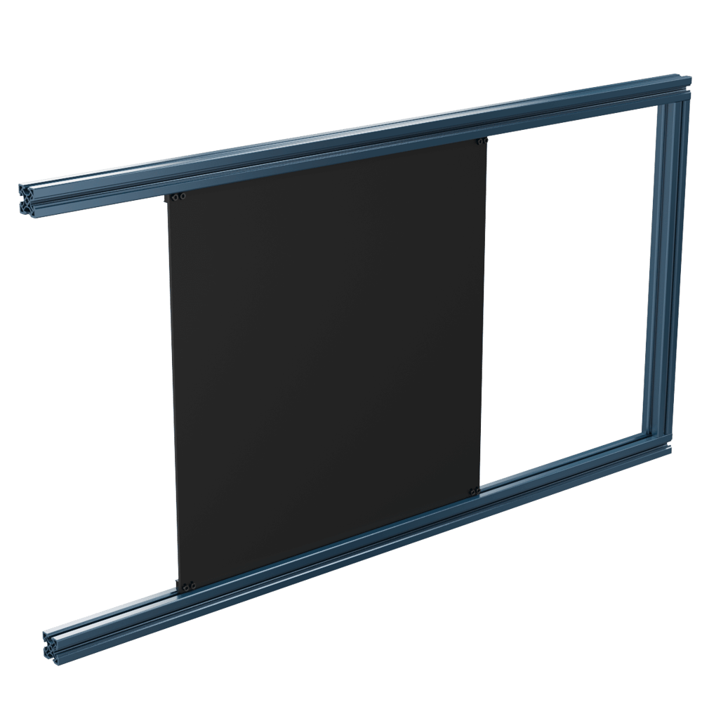
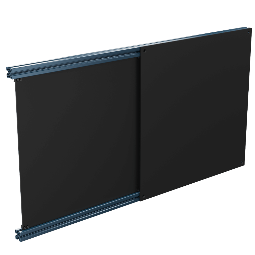
Panel sliding doors (ST-DR-001-0001) are intended for no-load applications. Space optimisation, division of workspaces and aesthetics are common use cases. These panel sliding doors by default are a 1/4in (6.35mm) thick panel with a profile of 675mm x 675mm, but if a custom size is required, please consult our Application Engineering department.
|
Guidelines for Panel Sliding Doors Installation
When adjusting the panel sliding doors to your Vention setup, ensure that there is an opening on either side to slide the panel in before fully closing off your door frame. The panel sliders are intended for use within the t-slots only and as such are designed to be captive once the assembly is complete.
Squareness of the frame is very important for smooth sliding of the panel doors. To assist with this, use structural framing components with HP-features. If the doors are still sliding, it may be necessary to loosen the frame slightly and tighten after achieving the desired amount of resistance when sliding.
The stationary side of the sliding door can be created using a panel mounted on the outside of the frame or inserted into an adjacent t-slot (such as with ST-EXT-002-XXXX, ST-EXT-005-XXXX, or any other extrusion with multiple t-slots per face).
 45x45mm Extrusion with Stationary Panel | 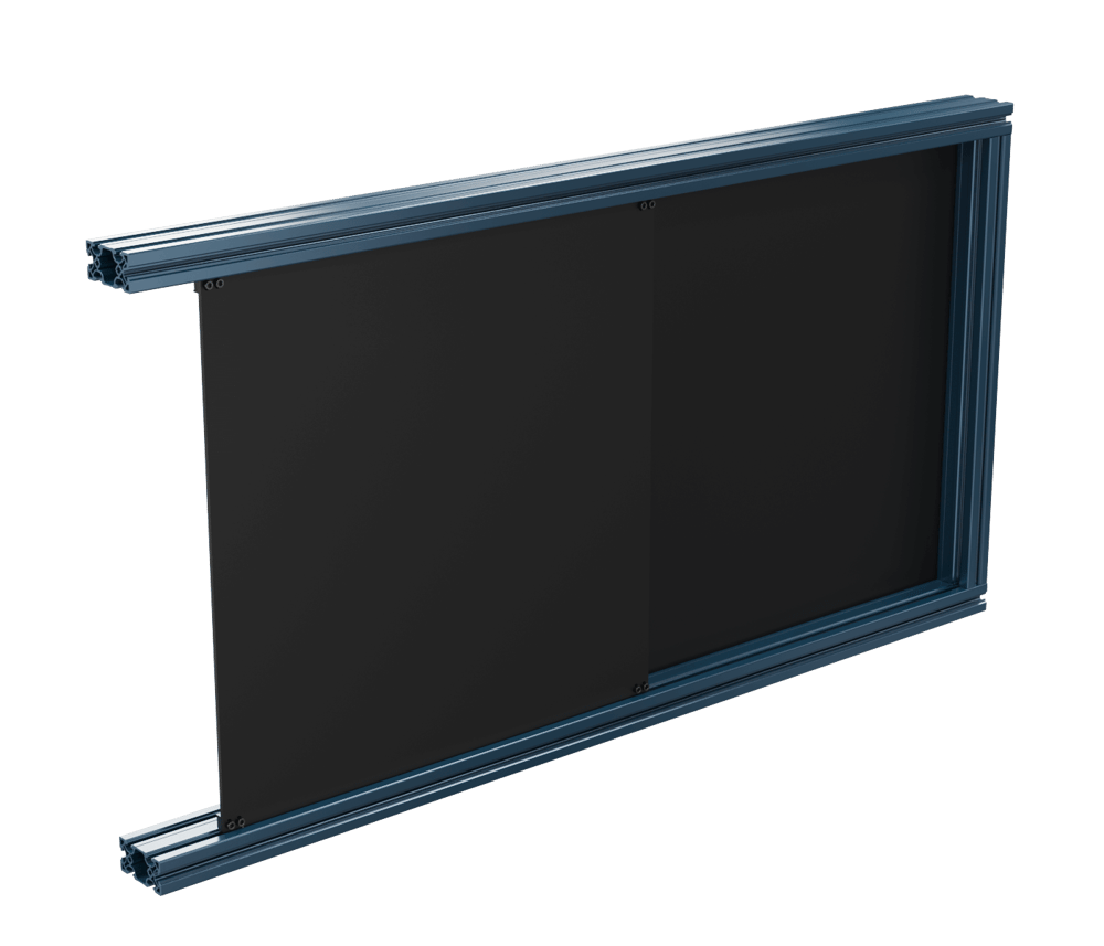 45x90mm Extrusion with Stationary Panel |
Adjustment of Panel Sliding Doors
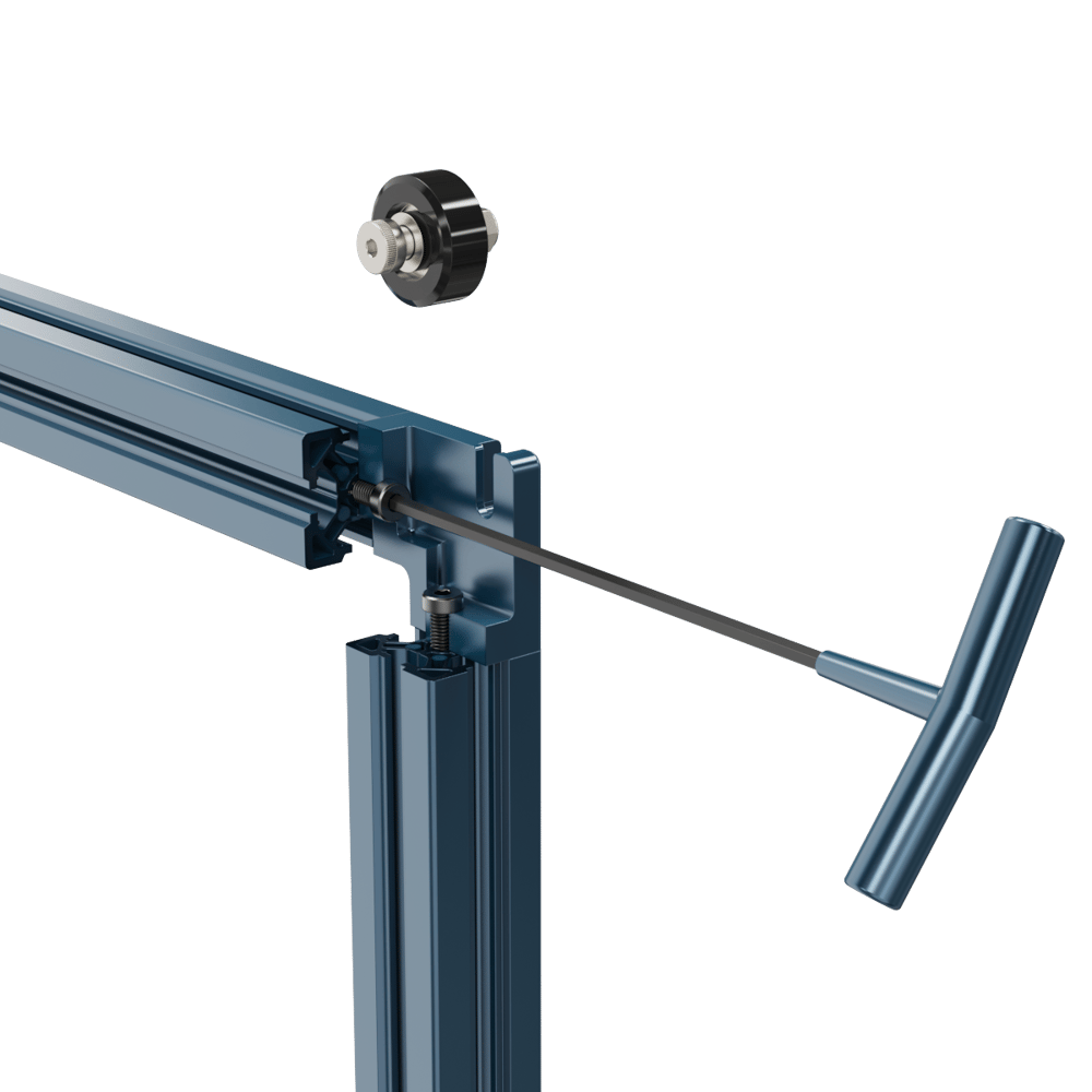
To adjust the sliders position on the panel, which can help in ensuring that the door slides smoothly, simply use an 5mm T-handle like the one that is included in the welcome box. This will allow for enough adjustment to account for slight misalignments or size differences in your frame.
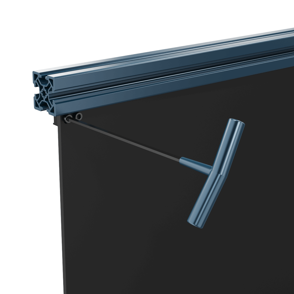 Panel Sliding Door T-Handle Adjustment |
Extrusion Sliding Doors
Sliding door frame connectors (ST-DR-002-0000) can be used to create a sliding door using an extrusion frame. This allows for all the flexibility of Vention’s 45x45mm profile extrusions on both the stationary and moving components of the door.
The sliding door frame connector kit allows for the creation of either horizontal or vertical sliding doors. When creating a vertical sliding door, ensure that a locking mechanism is added to avoid any safety concerns. See the end of this document for some potential options. If your application has specific safety requirements, please reach out to our Application Engineering department.
Guidelines for design with Extrusion Sliding Doors
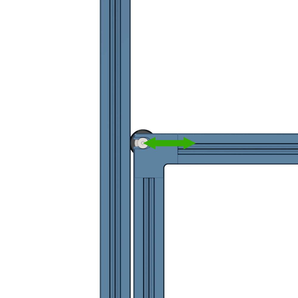
To avoid any interference with other extrusions within the enclosure or workstation, the sliding door frame connectors have an in-built offset, which will allow you to slide freely without worry of hitting any other parts on the frame.
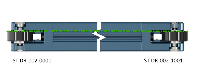
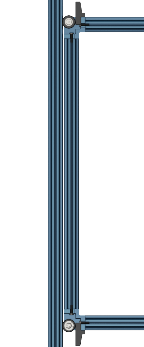
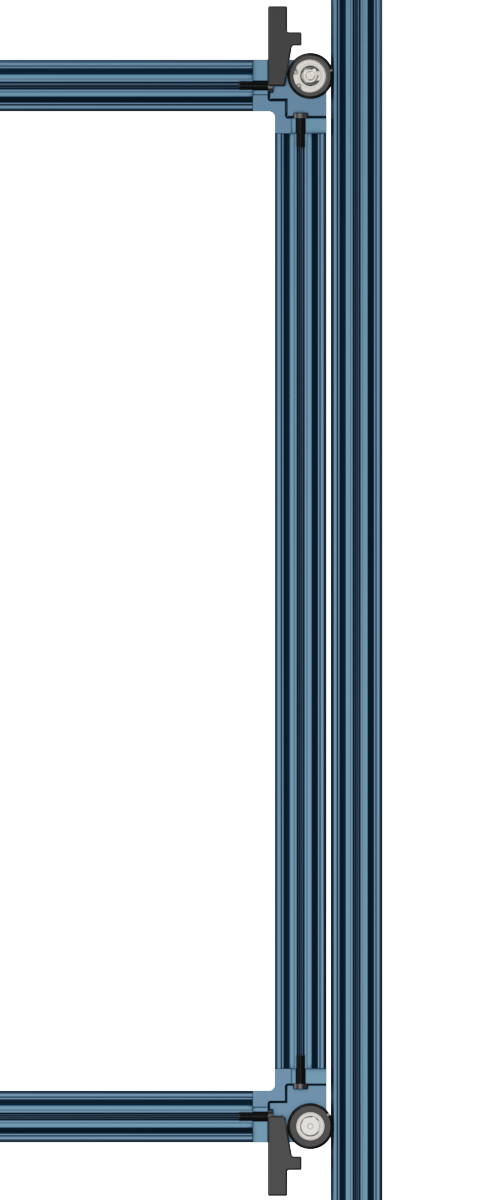
ST-DR-002-000X and ST-DR-002-100X are shown below, and when building your door frame, it is critical to ensure when assembled they are oriented correctly. Otherwise, the door will not roll smoothly in the mating extrusions. Below is an example of ST-DR-002-000X and ST-DR-002-100X being oriented correctly.
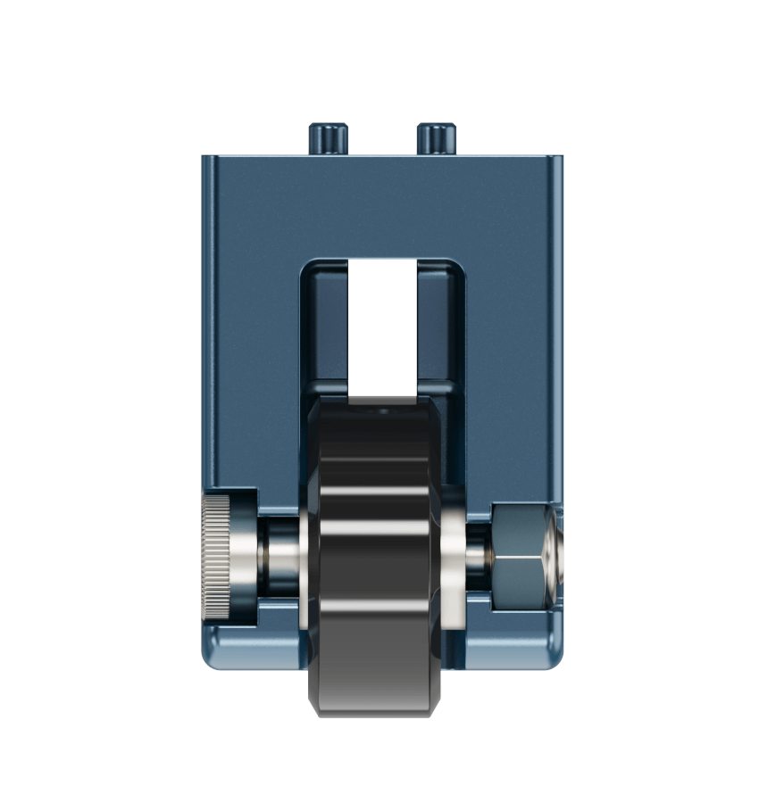 ST-DR-002-000X Wheel Offset | 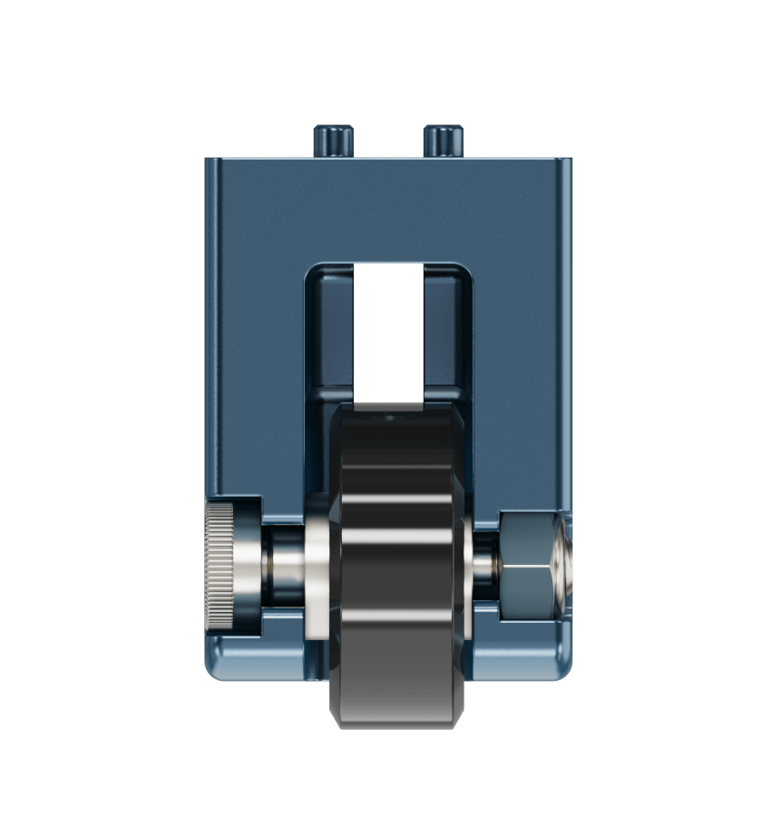 ST-DR-002-100X Wheel Offset |
 Correct Corner Orientation | |
Assembly and Adjustment of Extrusion Sliding Doors
When assembling the sliding door frame connectors onto your extrusions, the following are critical to proper installation:
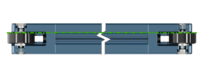
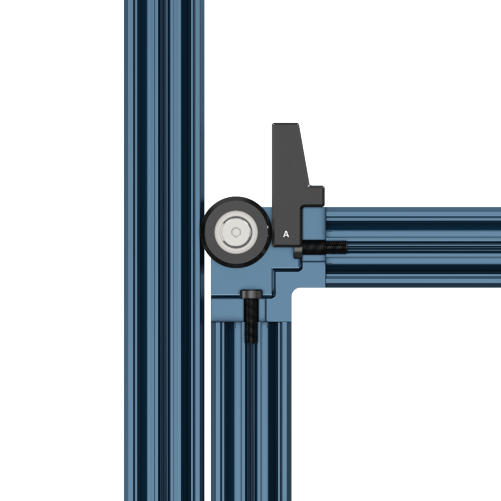
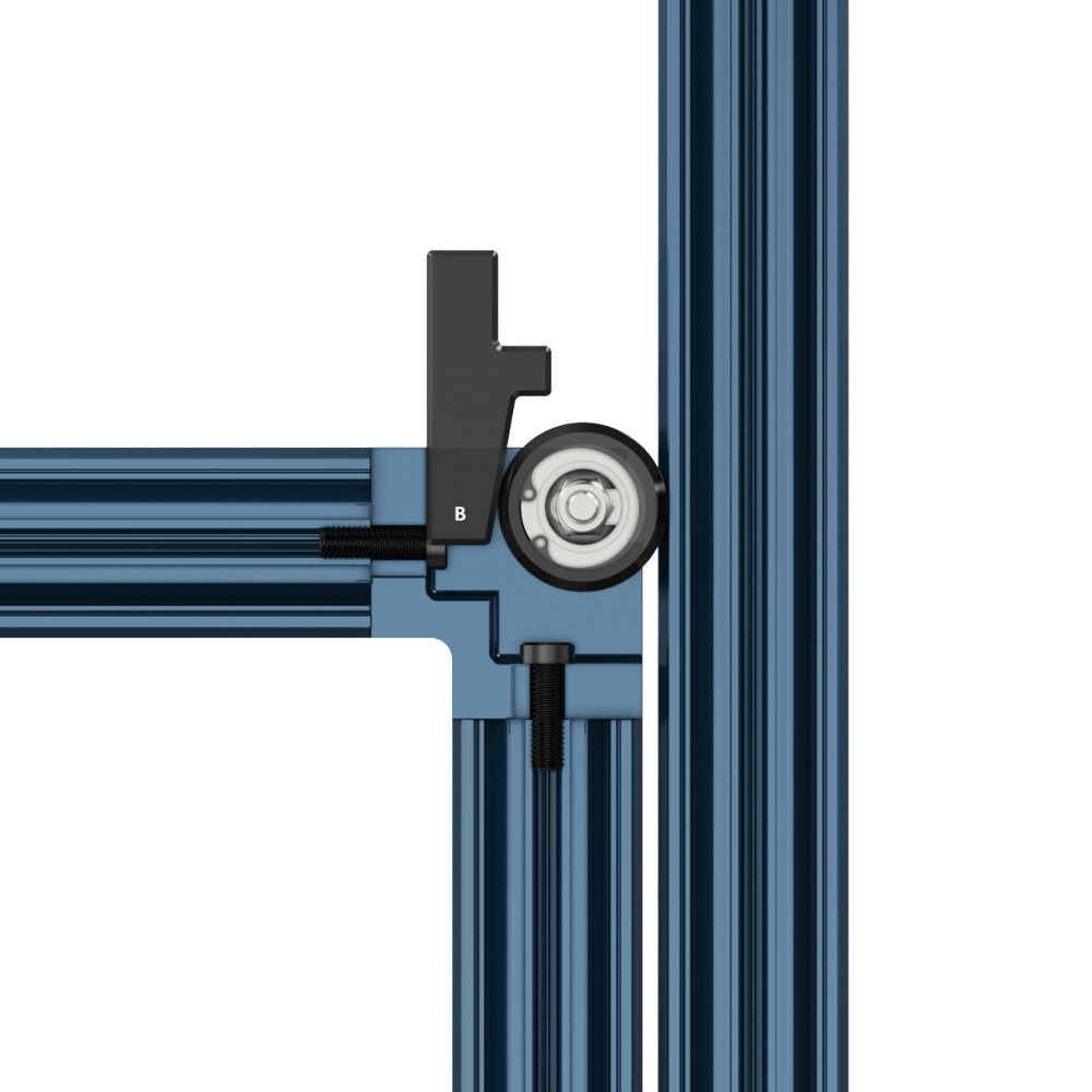
1. Ensure that the frame connectors are arranged so that the offset is in the same direction, which can be accomplished by having ST-DR-002-000Xs and ST-DR-002-100Xs on opposite diagonals. This is shown in the diagram below with ST-DR-002-000X (A) shown in Magenta, and ST-DR-002-100X (B) shown in Green.
 Correct Corner Arrangement |
 Correct Corner Arrangement Wheel Offset |
2. Ensure that the slot of each corner connector is perpendicular to the t-slot the extrusions that the door will be sliding along, otherwise adjustment will not be possible,
 Correct Slot Orientation |
3. Loosen the shoulder screw to release the wheel assembly from the corner connector. This allows for the corner connector to be fastened to the tapped ends of the two extrusions. Once the corner connector has been fully fastened to the extrusions, squeeze the wheel assembly and drop it back into the corner connector. Ensure that they are attached to the extrusions according to Steps 1 and 2 of this process.
 Fastening the Corner Connectors |
4. Ensure that all additional structural and framing elements (plates, extrusions, etc.) are kept on the frame side opposite to the door’s offset, this will prevent the door colliding with these components when sliding.
Once your sliding door is fully assembled, it is time to insert it into the surrounding enclosure. When assembling, using the provided Sliding Door Adjustment Tool (HW-TL-012-0000) is highly recommended. This tool will allow you to set the nominal spacing on one side of the door and adjust for any frame sizing or misalignment on the other. To properly adjust your door, perform the following:
1. Use Tool Side “A” to give a nominal gap to two corner connectors that are connected to the same extrusion. Tighten these connectors so that the locking patch of the nut is engaged.
 Using Tool Side "A" |
|
2. Use Tool Side “B” to wedge the remaining frame connectors snuggly into place, and fully tighten them so that the locking patch of the nut is engaged.
 Using Tool Side "B" |
|
Locking of Extrusion Sliding Doors
To lock your door in place, many options in the Vention ecosystem can be used. A gate bolt (ST-SE-006-XXXX) can provide a secure solution and can even be used with a Safety Interlock. Locating pins or the Latch-style toggle clamp (HW-LT-003-0001) can all be effective solutions for fastening your door.
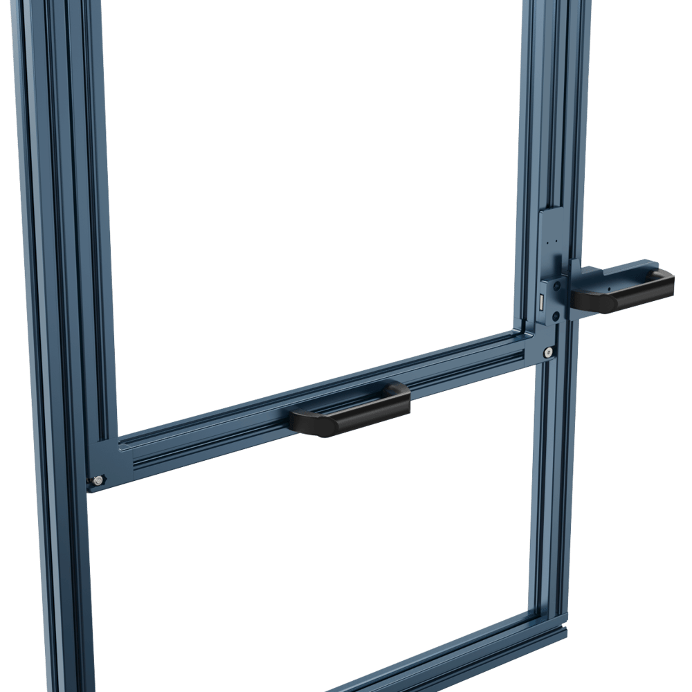 Gate bolt Locking | 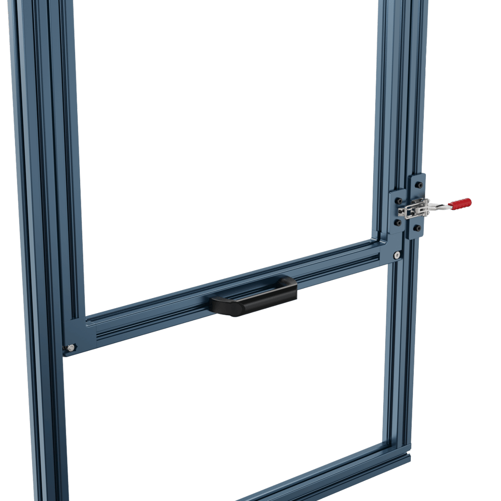 Latch Locking |
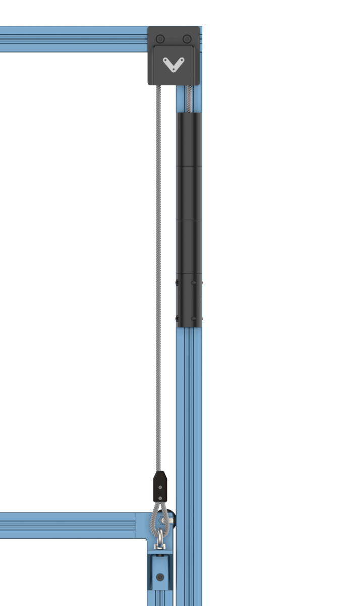
Vertical Sliding Door Counterweight Kit
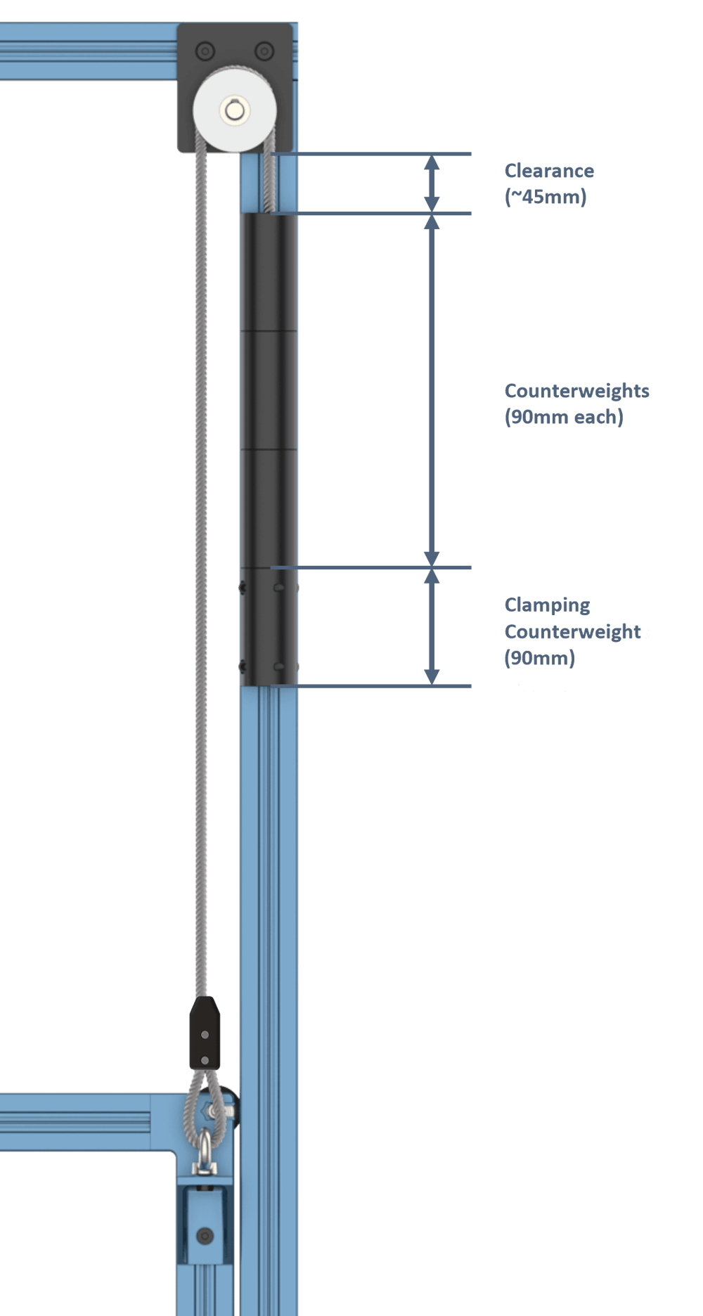
When using Vention’s extrusion sliding doors in a vertical configuration, it is recommended to pair them with a set of two vertical counterweight kits (ST-DR-003-0001). This will allow for the door to be suspended in the air, without needing constant support from the user.
One of the most critical details to properly designing a vertical sliding door with counterweight is the weight of the door, which can be easily found in MachineBuilder. If ever you are unsure how to calculate this, please contact our Application Engineering department for guidance. Once this has been determined, the number of 1kg counterweights (ST-DR-003-0006) can be determined. These must be added into the MachineBuilder design by connecting them to the top of the 1kg clamping counterweights.
Additionally, the design guidelines listed below should be followed when using the counterweight kit for vertical sliding doors:
1. Always place the counterweight kit or kits on the inside of the enclosure. This will ensure no safety risks for users on the outside.
2. Ensure that the extrusion at the top of the door frame, which the counterweight pulley blocks will be attached to, is horizontal and spans the entire door frame as shown in the assembly instructions below. This will allow for adjustment for side to side adjustment of the suspended counterweights.
3. Ensure that some clearance is given on either side of the suspended counterweight across the entire travel of the counterweights.
The counterweight kit should be assembled as follows:
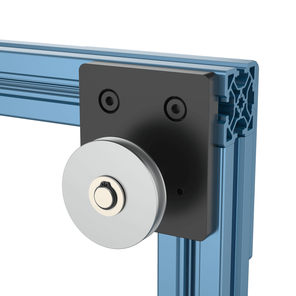
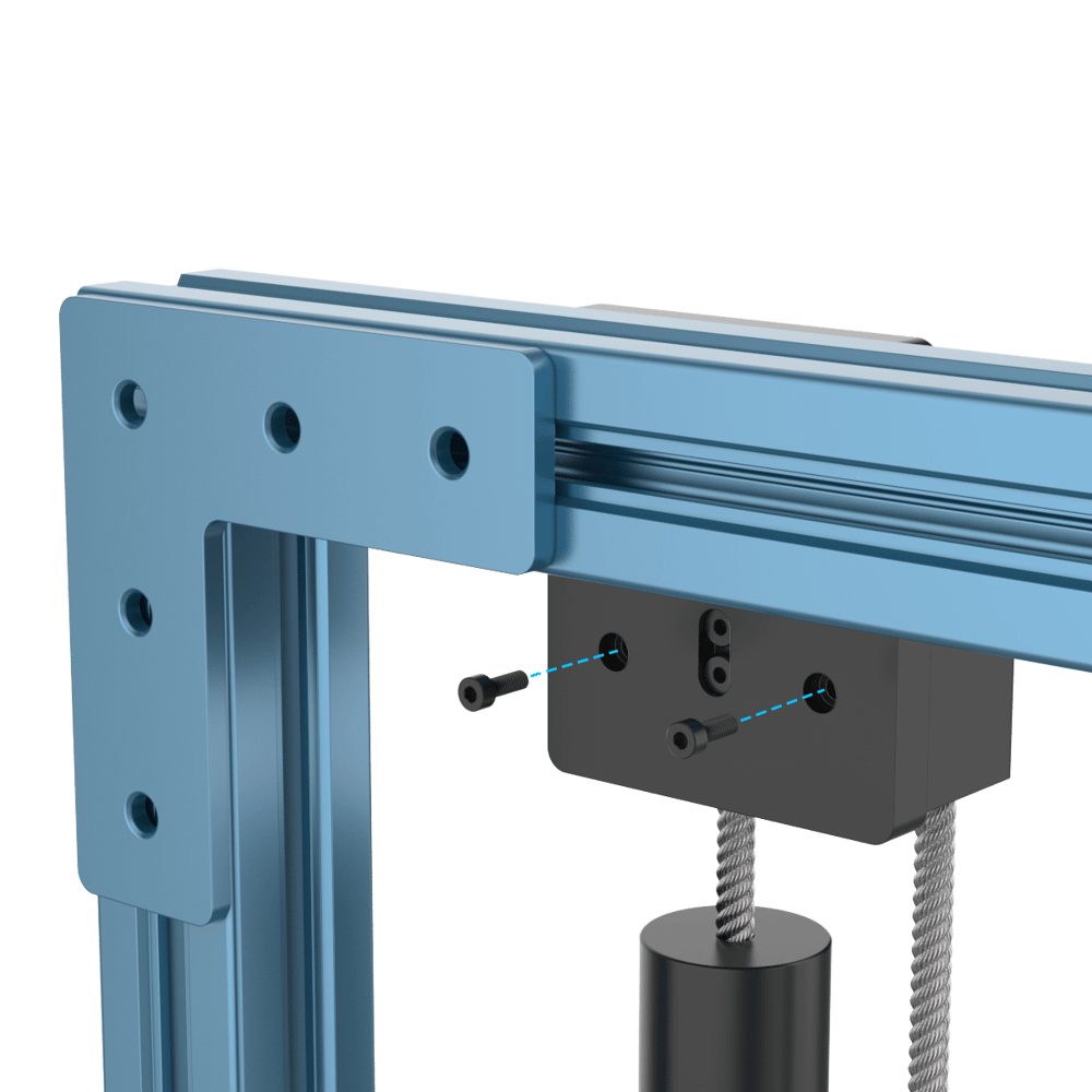
1. Attach the pulley block plate to the extrusion frame using the provided M8 bolts. Do not fully tighten these screws, as the block will be moved in the horizontal t-slots to fasten the pulley cover.
|
2. Measure the correct amount of rope needed for the size of door in your design. To do this:
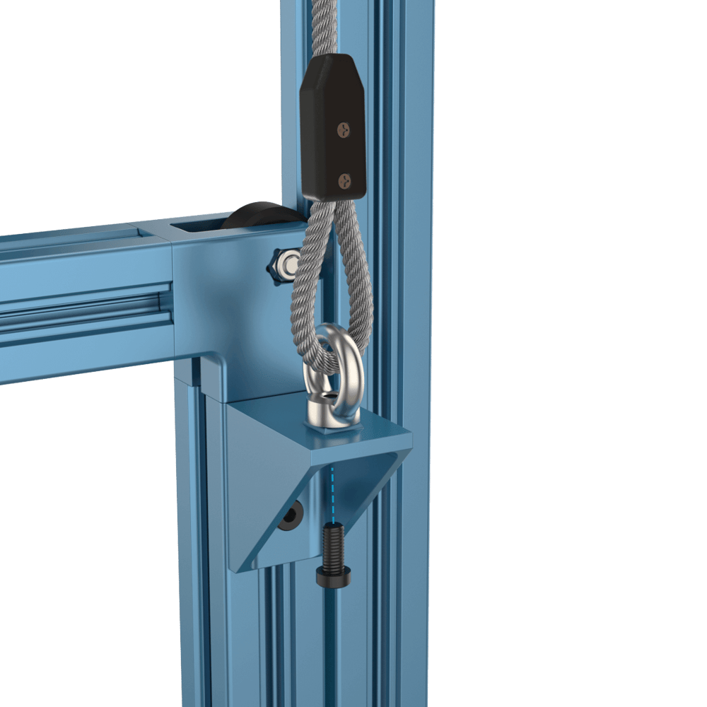
a. Attach the provided 67.5mm x 67.5mm Gusset with Locators (ST-HP-003-0007) and fasten the eye-nut attached to the 3m rope segment with the provided M8 x 18mm bolt.
|
b. Lower your vertical door to the bottom of it’s stroke. This will ensure that the counterweights will not contact the pulley block.
c. Pass the rope segment over and along the pulley.
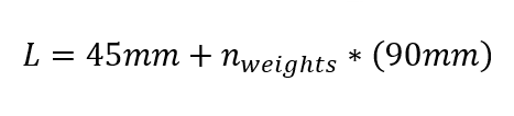
d. Mark the location of the rope where it will be cut. Based on the number of counterweights needed, add 90mm of clearance.
NOTE: The clamping counterweights weighs 1kg and is also 90mm long, so this should be counted as a “required” counterweight in this equation.
To calculate the length of the overhanging rope use the following formula.
NOTE: the value for n should be rounded to the nearest integer.
|
If your system has multiple counterweight kits, divide the value for n by the number of kits.
|
|
e. Once the location is marked, to ease cutting of the rope a small amount of tape can be applied to prevent fraying.
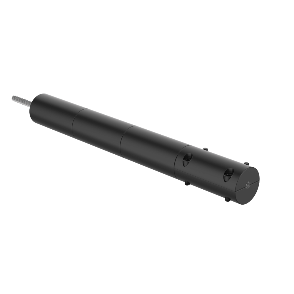
3. Slide the cut rope through all of the 1kg counterweights (ST-DR-003-0006) and add an additional ~100mm of rope.
|
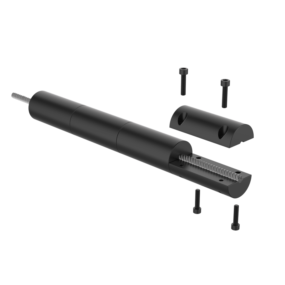
4. Fasten the clamping counterweights to the rope and loop the rope and all counterweights over the pulley.
|
5. Slide the pulley block to the side to uncover the counterbores in the rear. Fasten the pulley block cover with the provided M4 screws.
|
6. Once attached, slide the completed block back into position and fully fasten the M8s into the extrusion.
|