Cable Management Ecosystem
Contents
Overview
Cable management is an important part of the design process in terms of functionality, aesthetics and safety. A design with proper cable management offers a professional look and ease of maintenance for its users.
Cable measurements table
| Cable type | Part number | Cable outside diameter (mm) | Connector outside diameter (mm) | Weight per meter (g/m) | Minimum bend radius (mm) |
|---|---|---|---|---|---|
| M12 end-stop cable | CE-CA-018-XXXX | 5.0 | 14.6 | 46 | 25 |
| MM1 Stepper motor cable | CE-CA-020-XXXX | 6.9 | 22.2 | 47 | 25 |
| MM2 Stepper motor cable | CE-CA-020-XXXX | 15 | 26 | 300 | 75 |
| MachineMotion1 control device cable | CE-CA-022-5000 | 6.2 | 14.6 | 56 | 45 |
| MachineMotion2 control device cable | CE-CA-022-5001 | 7.0 | 14.5 | 63 | 39 |
| Safety device cable | CE-CA-028-XXXX | 5.1 | 15.0 | 44 | 25 |
| 6 mm pneumatic tubing | CA-TB-006-XXXX | 6.0 | 10.8 | 33 | 40 |
| Pneumatic actuator position cable | CE-SN-008-0001 | 2.6 | 15.0 x 15.0 (square) | 12 | 10 |
Note: If possible, position cable connectors outside of cable raceways or drag chains. This helps keep cable bundles small and makes maintenance easier.
Drag Chain
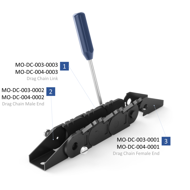
Drag chains (MO-DC-XXX-XXXX), also known as cable carriers, and cable tracks carry electrical cables and pneumatic hoses to the moving side of an actuator. Each chain is composed of repeating links into which the cables are inserted. Cable carrier ends must be attached to a framing component.
Installing the drag chain
You will need a flat blade screwdriver and Vention T-handle. Drag chain ends come in two types, male and female. Male ends have two screws, whereas female ends have two holes into which the drag chain fits.
To separate or assemble links in a drag chain:
- Using a small flat blade screwdriver, open the three crossbar links on either side of the break point.
- Insert screwdriver between the links and lever them apart.
- Re-attach links by squeezing the ends of the male link (see description below) and pushing the male and female ends together.
- To install the male end, remove the two screws with a flat head screwdriver then reinstall them with the drag chain link in place.
- To install the female end, open the last three crossbar links and squeeze the drag chain link. Bend the female drag chain end slightly to install onto the drag chain link.
⚠ Important: Always remove screws before assembling male drag chain ends. Failure to do so may result in bending and damaging the brackets.
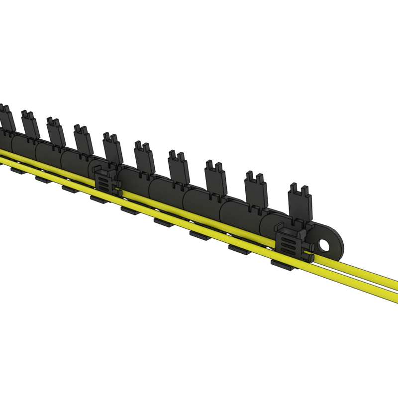
To insert cables into the drag chain, open the crossbars on each link with a screwdriver. Snap them closed with a push.
Drag chain strain relief brackets are included with each drag chain end. Insert the brackets between the crossbars of every fifth link, and attach cables to them with zip ties.
Designing with drag chains
Vention offers two sizes of drag chain (shown below). The right size for you depends on your cable bundle size.
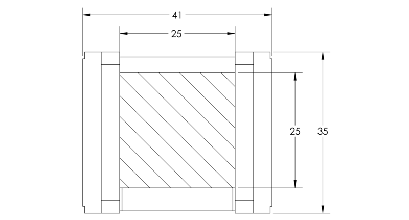
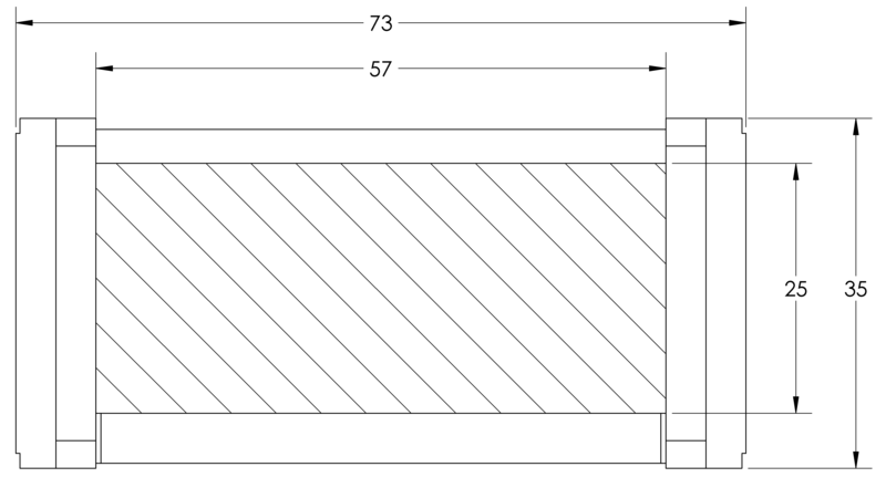
⚠ Important: Always include 10% extra space around each cable and 20% around pneumatic hoses, to allow the them to move freely when the drag chain is bent.
It is most cost-effective to place the fixed side of the drag chain in the center of travel, because this minimizes the number of chain links. In this case, the required length is:


The max unsupported length depends on the drag chain’s fill weight. Determine your fill weight with reference to the cable measurements table. Max unsupported length is therefore:

Where length is in meters, weight is in kg. When mounting drag chains vertically, we recommend simply hanging the chain. That way you won’t need any extra supports, so you’ll save costs and hassle.

Cobot dress pack
Installing the cobot dress pack
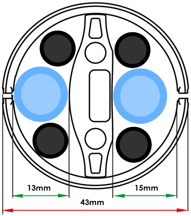
When installing the cobot dress pack, the first step is always to insert the tubes and cables needed. This kit has two zones that can take components of up to 13mm and 15mm (see picture below).
Once all the components are fitted in the dress pack, the next step is to mount it on the robot.
- Install the Dress Pack Flange Offset Mount (HW-CA-005-0004) between the EOAT and the wrist of the robot using the provided M6 screws (18mm or 20mm depending on the EOAT).
- Install the Strain Relief Clamping Bracket on the Dress Pack Flange Offset Mount with the provided M5 screws. Make sure the strain relief is pointing away from the robot.
- Install all the mounting brackets without strain relief on top of the forearm and upper arm of the robot at the start and end of each segment. Ensure the velcro is fully tightened and meets about halfway around the arm. Do not cut the velcro yet.
- Clamp the last link of the dress kit chain in the mounting bracket with the strain relief.
- Clamp the dress pack chain to the next mounting bracket while leaving some slack in the chain.
- At slow speed, while keeping a hand on an estop, run the robot to confirm that there is enough slack in the dress pack to allow for all the needed motions.
- Adjust the mounting bracket and the slack in the dress pack accordingly.
- Clamp the dress pack in the next mounting bracket, while keeping the dresskit straight.
- Repeat steps 4 to 7 for the upper arm and base of the robot.
- Test all motion at full speed and adjust accordingly.
- Once certain the dress pack is not constraining the robot and does not get stuck during motion, the excess velcro can be cut on every mounting bracket.
- If the dress pack is too long, shorten it by grabbing it with two hands and twisting it. Make sure to not shorten it too much, since this will reduce the resistance to torsion if the removed links are reinstalled.
- Using the tie wraps provided fix every tube or cable coming out of the dress pack to the strain relief fingers of the Strain Relief Clamping Bracket.

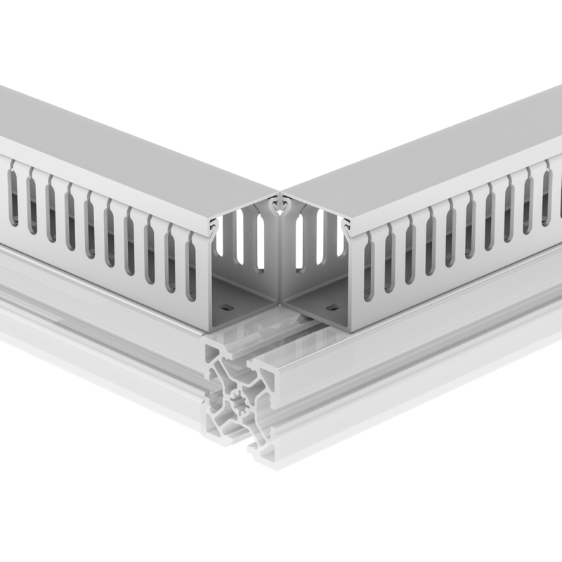
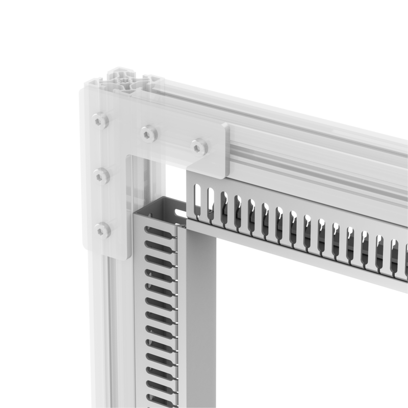
Cable Tray
Installing the cable tray
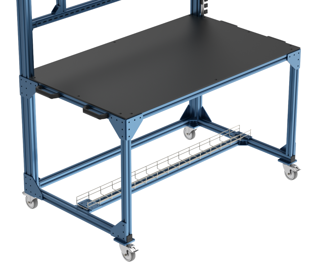
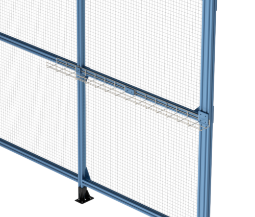
The cable tray can be mounted with plates to clamp it to an extrusion on its side or its top. The following images shows some examples of how it can be done.
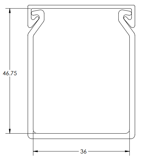
Wiring duct
Installing the wiring duct
Installing a wiring duct is quick and only requires a 4 mm hex key.
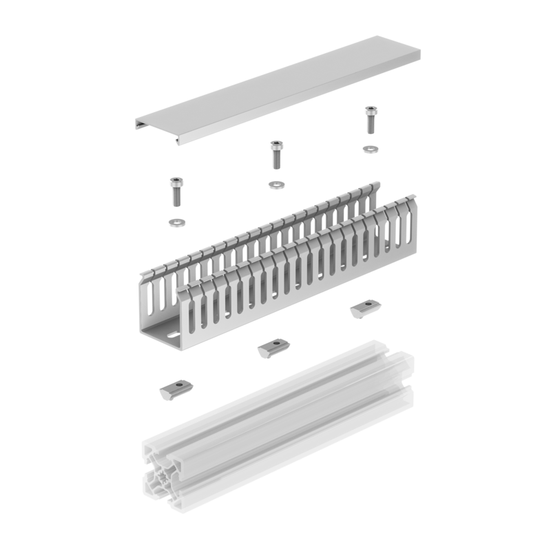
- Remove the wiring duct cover to access the mounting holes.
- Place a washer (HW-WS-005-0002) between the wiring duct base and the screw (HW-FN-005-0016). Using a 4 mm hex key, tighten the screws to secure the wiring duct.
- Place the cables inside the wiring duct and snap the cover in place.
Note: To avoid deforming/damaging the raceway, install the fasteners 200 mm apart (that is, every four slots), and do not over-tighten. In general, they should only be tightened by an extra quarter turn once resistance is felt.
If the walls of the raceway tilt inwards due to over-tightening, remove the cover and use your hands to gently spread apart the walls, in order to create an outward force that helps secure the cover.
Adjusting the raceway length and modifying the teeth
The raceway can be cut to custom lengths with a duct cutter or hacksaw. Cut the wiring duct U-channel and cover separately, to avoid slipping and uneven cuts. Once cut, you may want to deburr the edges with a box cutter.
You can remove the wiring duct teeth to allow larger cables to exit at various distances from its ends. To do so, a duct or box cutter can be used. To use the box cutter method, score the base of the teeth and bend the teeth away from the score line until they snap off.
Wire fill
The recommended raceway wire fill percentage is 50%. This takes the material’s thickness into account, as well as the air space between cables.
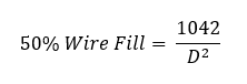
The above equation calculates the number of cables, at a given diameter D, that can fit in a 40 x 50 mm raceway.
The variable D must be expressed in mm.
Note: Air space varies with the cable diameter (for instance, larger cables have more air space between them).
Accessories
Cable ties are a quick way to organize cables. Add screw-in cable tie mounts (HW-TW-001-0001) at every point where the cables must be supported.
5 mm x 250 mm Cable Ties (HW-TW-002-0001).

