Shock Absorber
Overview
The installation of shock absorbers in vertical lifting applications is critical to prevent component damage in the event of payload free fall. This document outlines shock absorber specifications, applications, and configurations to ensure proper function.
Applications
The main application of shock absorbers is vertical lifting. They act as an effective safety measure in the unlikely event that the assembly enters free fall. This can occur if there is a loss of power and the power-off brake fails to activate, or if a motor stalls. In either case, the shock absorber prevents the assembly components from being damaged upon impact.
Technical Specifications
| Part Number | HW-BP-002-0000 |
| Overall Height (mm) | 242.5-272.5 |
| Stroke Length (mm) | 75 |
| Minimum Effective Falling Mass (kg) | 54 |
| Maximum Impact Velocity (m/s)* | 3.5 |
| Maximum Energy Capacity per Cycle (J) | 750 |
| Maximum Shock Absorber Force (N) | 10000 |
*Adding additional shock absorbers does not increase the maximum impact velocity, only the maximum energy capacity.
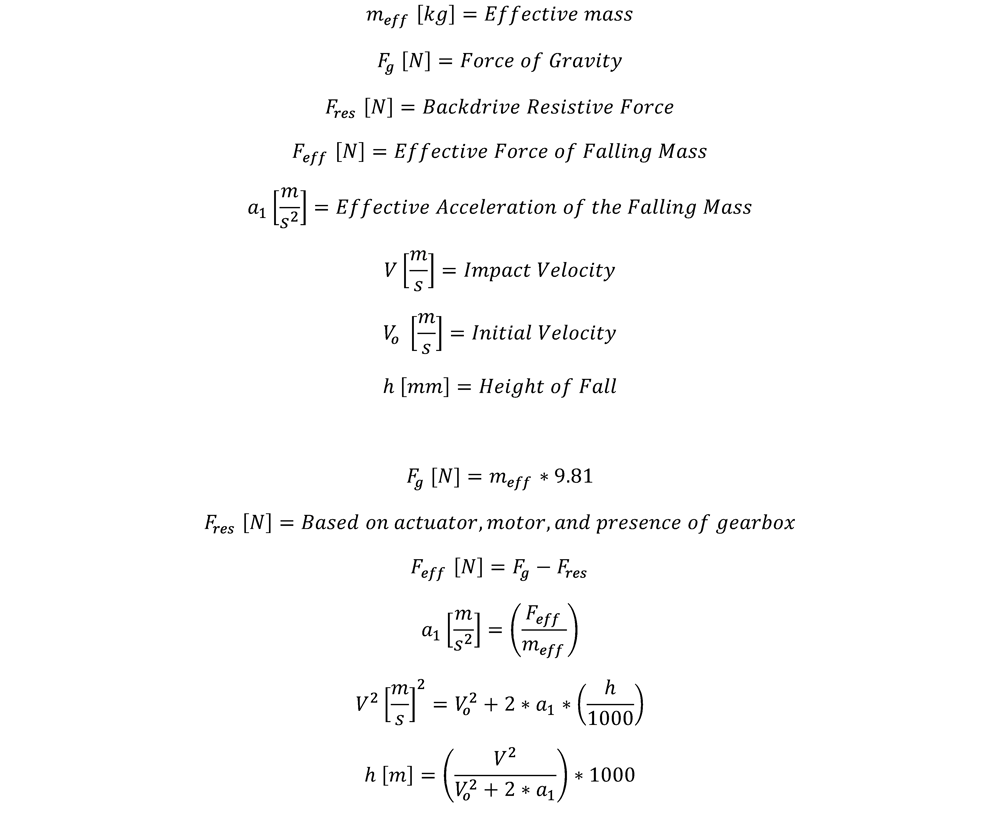
Impact Velocity
In practice, a falling object never achieves true free fall, because many forces affect its acceleration. Among the most impactful are the forces created by the actuator and motor to resist motion.
Through experimental analysis, the forces generated by Vention’s actuators and motors have been calculated, as shown in the table below.
| Actuator and Motor Size | Backdrive Force (N), Fres | Backdrive Force with a 5:1 Gearbox (N), Fres |
|---|---|---|
| Timing Belt, with 100 mm NEMA | 32.5 | 162.5 |
| Timing Belt, with 156 mm NEMA | 47.5 | 237.5 |
| Enclosed Timing Belt, with 100 mm NEMA | 50 | 250 |
| Enclosed Timing Belt, with 156 mm NEMA | 80 | 400 |
| Rack and Pinion, with 100 mm NEMA | 12.5 | 62.5 |
| Rack and Pinion, with 156 mm NEMA | 32.5 | 162.5 |
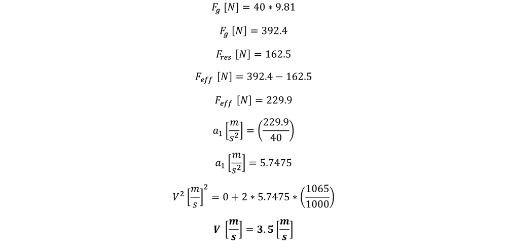
Using the values in the table above we can calculate the impact velocity of the mass:
Sample Calculation:
This example uses a weight of 40 kg, falling from a height of 1065 mm, assembled with a rack and pinion, 156 mm NEMA, and a 5:1 gearbox.
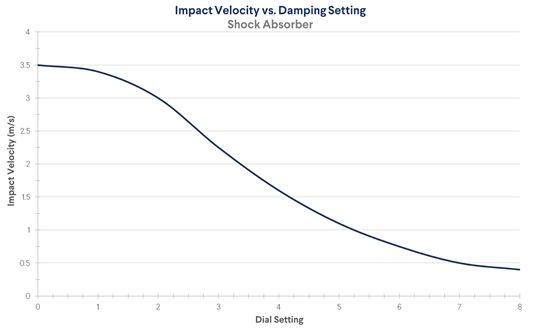
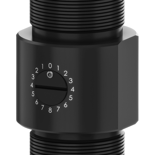
Damping Settings
Damping requirements are most dependent on the impact velocity of the falling mass. The chart below shows the optimal damping ratio for various impact velocities.
⚠ Warning: Shock absorber effectiveness is not guaranteed when using velocities outside the ranges recommended below. Follow these guidelines to both prevent component damage and maximize the shock absorber’s lifespan.
To set the damping rate:
- Ensure the set screw is loose before adjusting the dial.
- Align the set screw with the appropriate dial setting number (given the graph above). The settings are symmetrical, so the set screw can be set to the number on the left or right.
- After setting the damping rate, re-tighten the set screw to ensure the setting will not change over time.
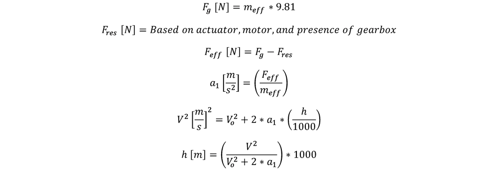
Maximum Allowable Free-fall Height
The shock absorber’s rated velocity affects many design decisions, including the allowable fall height. The formula below can be used to calculate the maximum allowable free-fall height.
This equates to the maximum height from which the payload could fall where the shock absorber would effectively dampen the impact. Above this height, the shock absorber’s effectiveness cannot be guaranteed.
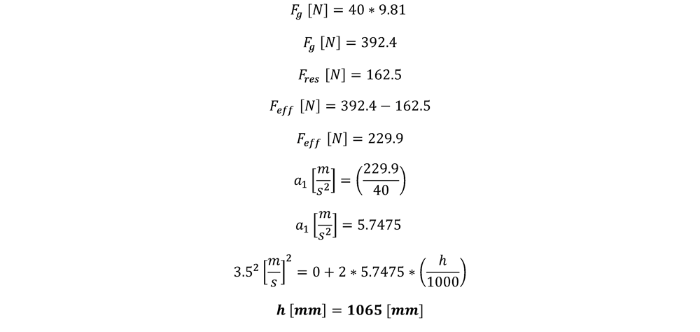
Sample Calculation:
This example uses a weight of 40 kg, assembled with a rack and pinion, 156 mm NEMA, and a 5:1 gearbox.
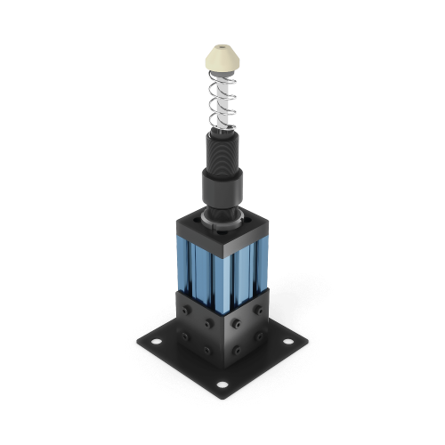
General Assembly Procedure
To install the shock absorber assembly, you must first fix the shock absorber mount (item 2.1 in the figure below) to the supporting structure.
The mount must be placed in a location that respects the Component Spacing detailed below. Be sure to bolt the mount to a structure (3) that is capable of handling the reaction force of the shock absorber.
⚠ Important: It is imperative that the shock absorber is mounted parallel to the axis of motion, otherwise both the shock absorber and the assembly may be damaged.
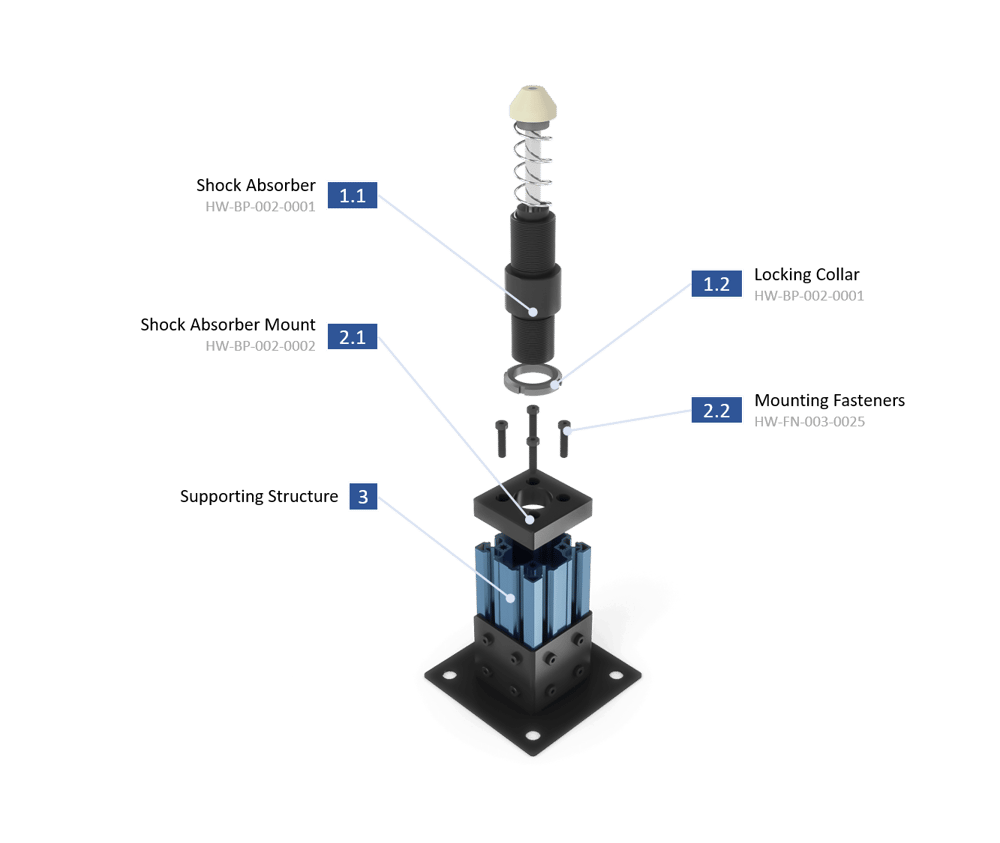
After fixing the shock absorber mount to the structure:
- Thread the locking collar (1.2) onto the shock absorber (1.1).
- Thread the shock absorber (1.1 and 1.2) into the mount (2.1).
- Set the shock absorber’s height with the locking collar (1.2).
Set the height so that the shock absorber’s stroke ends before the actuator’s travel. The tip of the shock absorber should extend at least 80 mm (75 mm stroke + 5 mm clearance) above the end of the actuator’s travel. This will protect the end of the actuator and allow the shock absorber to absorb the resultant forces.
Ideally, the supporting structure should be simple, rigid, and firmly attached to the floor, as in the above example. If floor anchoring is not possible, ensure the structure can handle at least the 10 kN reaction force of the shock, with a minimum safety factor of 4.
An example of a mounting configuration where the shock absorber cannot be bolted to the floor is shown below.
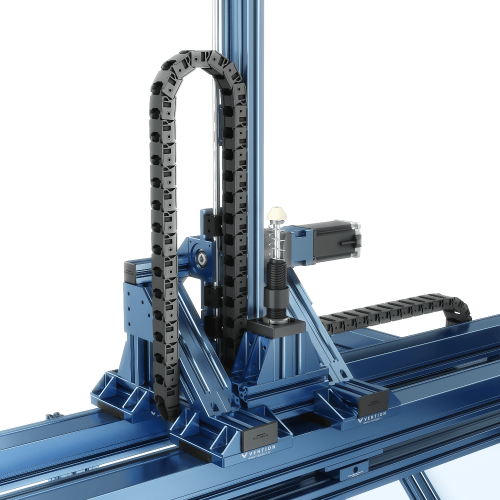
The above structure has been analysed and verified to be suitable for loads over 40 kN while the four bearings are each rated for 5 kN. This is an acceptable mounting configuration as the structure has a safety factor of over 4 and the combined bearings have a safety factor of 2. To ensure that your shock absorber mounting is appropriate, please contact Vention’s application engineering team.
Component Spacing
When mounting the shock absorber, you must consider the effect of the falling mass on the linear bearings. This impact is governed by the relationship between the location of the shock absorber, the center of gravity of the falling mass, and the position of the linear bearings.
The diagram below depicts a simple assembly of a free-falling mass, shock absorber, and bearings.
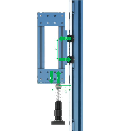
The bearings in the diagram will experience a dynamic load as shown. Referring to the Linear Guides & Accessories technical document, it can be seen that the maximum allowable force per bearing is 1000 N.
Given the weight of the free-falling assembly and the height of the fall, it is possible to determine bearing reaction forces and validate the component spacing. For ideal configurations, alter rr, rs, and rg so that the bearing reaction force Fr approaches zero.
The following equation calculates the bearing reaction force Fr. Input the known values for bearing spacing (rr), center of gravity distance (rg), and shock distance (rs), and solve for Fr. Make sure the value of Fr is below the bearing capacity.
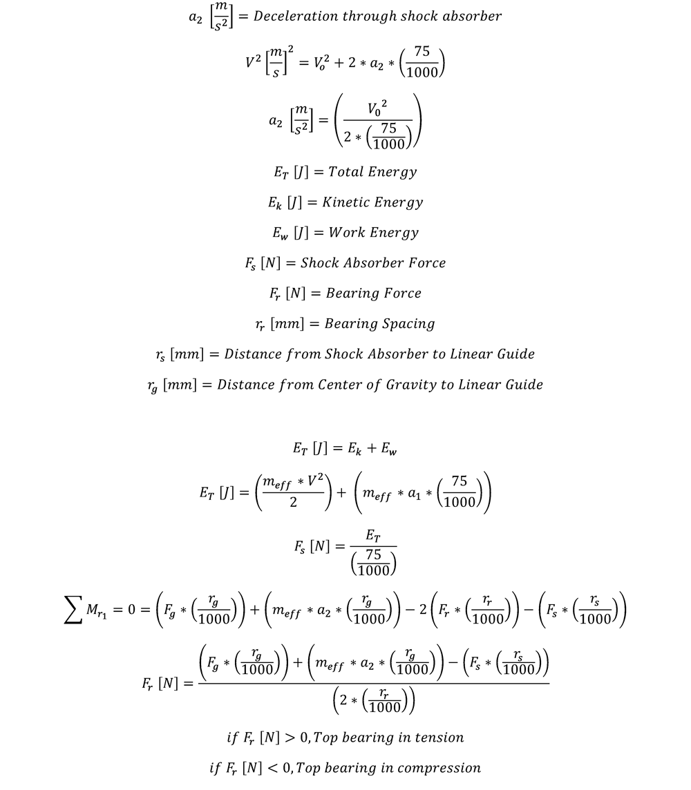
If possible, set the values of rs, rr, and rg during the design process to minimize Fr. This will ensure machine performance and longevity.
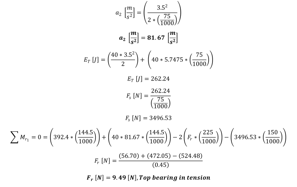
Sample Calculation:
For the given example, a weight of 40 kg, falling from a height of 1065 mm, with bearing spacing of 225 mm, a center of gravity distance of 144.5 mm, and a shock absorber distance of 150 mm. To determine the resistive forces created by the motor, a rack and pinion with a 156 mm NEMA motor and a 5:1 gearbox used.
The desired value of the forces exhibited on each bearing is below its rated value of 1000 N.