

Datasheet
Updated: Friday, April 14th 2023
Safety Module Datasheet (CE-SA-008-0000__3)
Contents
- Overview
- Features
- Important Notes
- Safety
- Cables & Connections
- Included cables
- Muting sensors
- Safety IN port
- Control IN port
- Power and Fuse Lights
- Technical specs
- General Specifications
- Electrical Specifications
- Safety RX - Pin-out - M12, female, 12-pin, A-Keyed
- Safety TX - Pin-out - M12, female, 5-pin, A-Keyed
- Muting 1 and Muting 2 - Pin-out
- Control IN - Pin-out - M12, male, 4-pin, A-Keyed
- Safety IN - Pin-out - M12, female, 12-pin, A-Keyed
- Safety OUT - Pin-out - M12, male, 12-pin, A-Keyed
- Applications
- Safety Module with light curtains (no muting)
- Safety Module with light curtains (with muting)
- Safety Module with laser scanner (no muting)
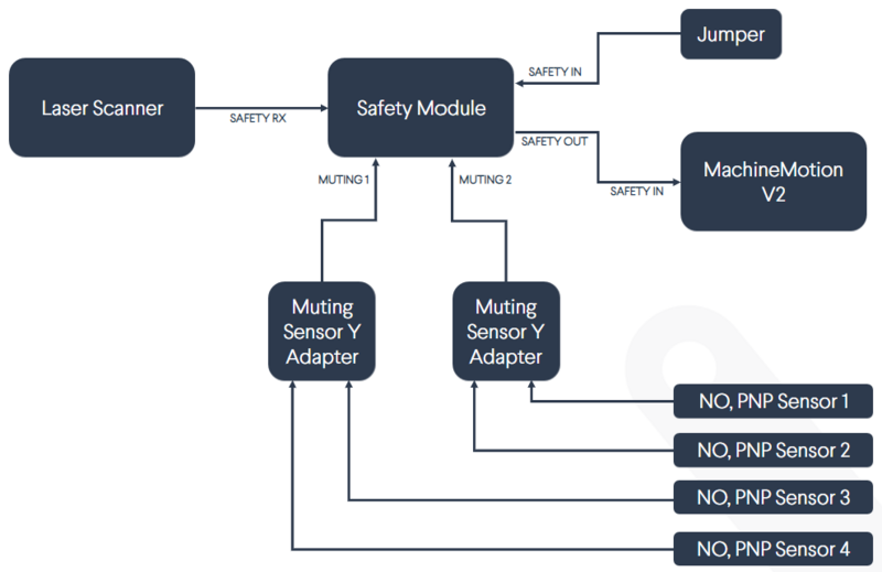
- Safety Module with laser scanner (with muting)
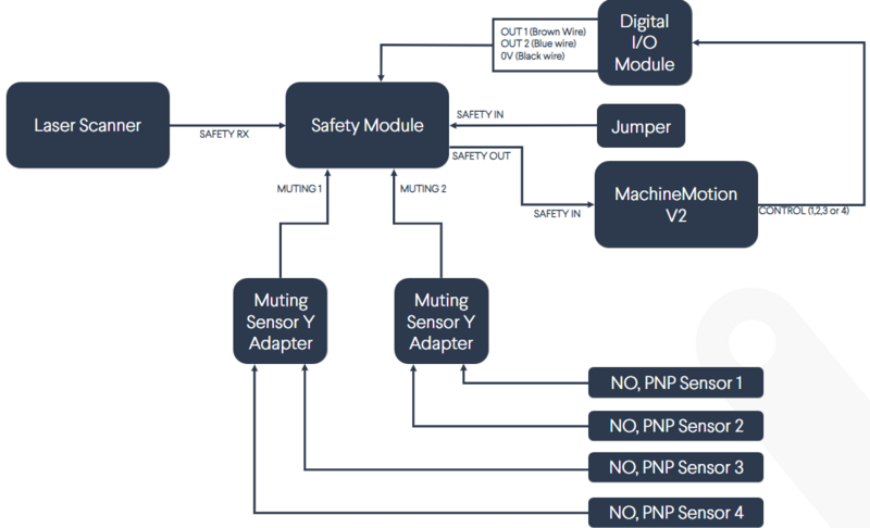
- Safety Module with laser scanner (with muting and bank switching)
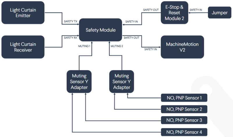
- Safety Module with e-stop module and laser scanner (with muting)
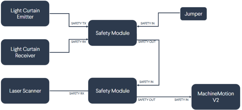
- 2x Daisy-chained Safety Modules V2 (light curtains and laser scanner)
- Safety Data
- EU Declaration of Conformity
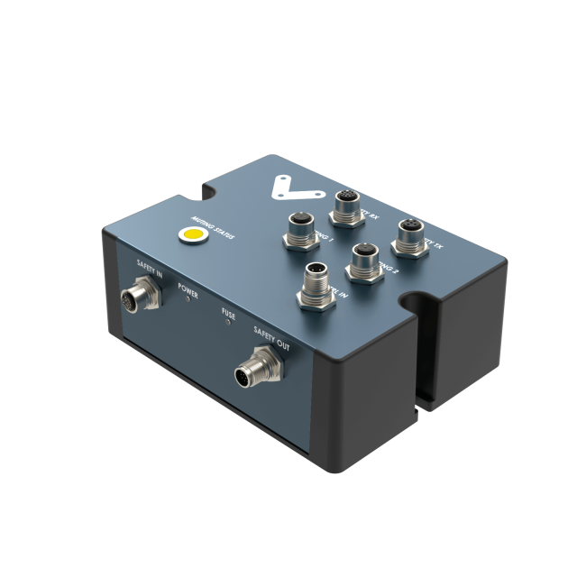
Overview
The Safety Module, CE-SA-008-0000__3 is intended to interface safety devices with the MachineMotion V2. The module is based on a multifunctional safety relay which enables and interrupts a safety circuit in a safe way. It can be used to protect people and machines with E-Stop modules and safety devices such as light curtains and laser scanners. If the safety device has a muting option, muting sensors can also be connected to the Safety Module. A yellow flashing LED on the module will indicate if muting is active.
Features
- Configuration-free, plug-and-play
- Compatible with MachineMotion V2
- Daisy-chainable
- Compatible with Datalogic SG4 & Keyence GL-R light curtains
- Compatible with Datalogic & Keyence laser scanners
- Inputs for muting sensor
- On-board LED to indicate muting
- Bank-switching control inputs for laser scanner
Important Notes
Safety

The Safety Module performs safety functions as a part of a whole installation or machine. A complete safety system normally includes sensors or input units, logic units and contactors or output units. The manufacturer of the installation or machine is responsible for ensuring proper functioning of the whole system. The total concept of the control system into which the Safety Module is integrated must be validated by the user. Vention cannot guarantee all specifications of an installation or a machine without being responsible for the risk assessment and the design of the safety system. Vention takes over no liability for recommendations which are given or implied in the following description.
The following items must be taken into consideration during the design, risk assessment & installation of the safety system :
- The Safety Module shall not be put into operation only after the safety functions have been tested during the commissioning.
- The use of the Safety Module does not prevent the automatic reset of devices connected to the Safety OUT port.
- The use of the Safety Module does not prevent the automatic start of the devices connected to the Safety OUT ports. According to EN IEC 60204-1:2018 and EN ISO 10218-1:2011 it is not allowed to restart automatically after emergency stop. Therefore the control systems of the connected devices have to disable the automatic start after emergency stop.
- Opening the Safety Module or implementing unauthorized changes voids any warranty.

Functional error! Danger to life, risk of serious injuries or property damage
- The Safety Module may only be connected to the equipment listed in this manual.
- The Safety Module is designed to operate in indoor environments without dust or high humidity. Dust and dampness may lead to malfunction. Do not install or operate the Safety Module outdoors.
Cables & Connections
Included cables
Safety Module comes with multiple cables. It is important to use the appropriate cable for the intended application and connect it properly. Cables are labeled on both ends to indicate how they should be connected to the module and safety device. The following cables are included:
- MachineMotion 2 Safety Extension Cable – 5 m (CE-CA-102-5001) - Connects Safety Module to MachineMotion V2 or to another Safety Module (in which case multiple Safety Modules V2 are daisy-chained). This connection is through the first Safety Module’s SAFETY OUT to MachineMotion V2 or the second Safety Module’s SAFETY IN.
Note 1: Two safety functions can be simultaneously interfaced with Safety Module (a safety device through SAFETY RX, and an e-stop module through SAFETY IN). However, only one safety device can be connected to the safety module at a time (laser scanner or light curtains). If you need to interface N number of safety devices to MachineMotion V2, you will need N number of safety modules (daisy-chained). Please refer to the User Manual for more information about the connections.
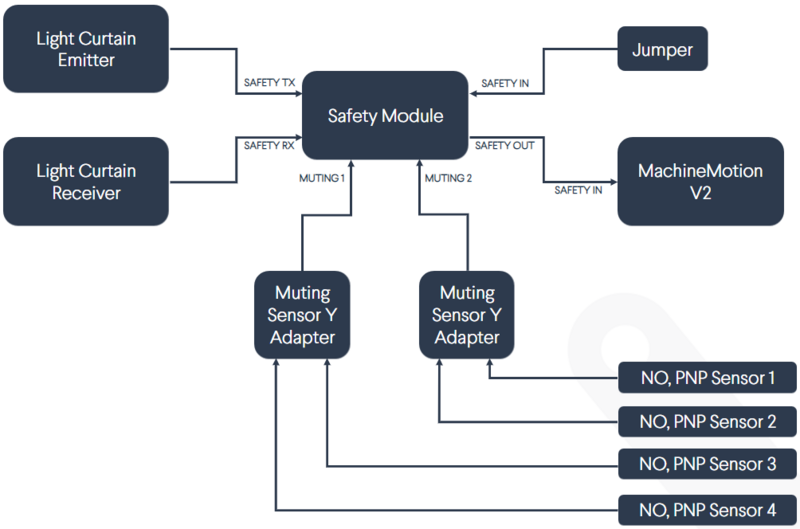
Note 2: If muting is required, connect the muting sensor in pairs to the Muting Sensor Y Adapter. Then connect the adapter to the Safety Module via the MUTING 1 and/or MUTING 2 connectors. Safety Module Muting Kit (CE-AP-002-0000) is not included with the Safety Module.
Note 3: If bank switching is required, connect the Bank Switching Cable for Safety Module and DIOv2 (CE-CA-067-5000) to the CTRL IN connector on the Safety Module and to the Digital IO Module V2 (CE-MD-001-0000__2) outputs. Bank Switching Cable for Safety Module and DIOv2 (CE-CA-067-5000) and Digital IO Module V2 (CE-MD-001-0000__2) are not included with the Safety Module
Muting sensors
The output type of the muting sensors that connects to Safety Module must be NO, PNP. Safety Module includes two Muting Sensor Y Adapters (CE-SA-107-0001), which allow you to connect up to four muting sensors.
Safety IN port
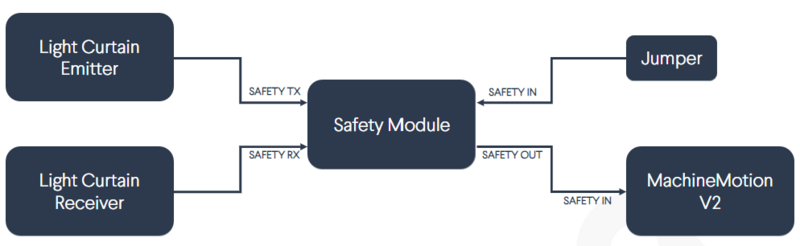
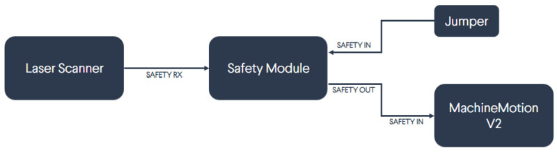
This port connects to the SAFETY OUT port of another Safety Module (if daisy-chaining multiple safety modules) or to an E-Stop and Reset Module 2 (CE-SA-007-0000). IMPORTANT: If the SAFETY IN port is not used, insert the included yellow jumper.
Control IN port
This port can be connected to an output port of a Digital IO Module (CE-MD-001-0001) using the included M12 A-Keyed 4-Pin Female to Leads Cable. It is intended for the bank switching option when using a laser scanner with the safety module.
Power and Fuse Lights
Safety Module is 24-V powered through the SAFETY OUT port. When powered, the white POWER LED light turns on. If 24 V and 0 V are shorted on one of the Safety Module ports, the red FUSE LED light will turn on, indicating a short fault. The LED will turn off when the short fault is removed.
Technical specs
General Specifications
| Part Number | CE-SA-008-0000__3 |
| Weight | 0.8kg |
| Dimensions | 19.0 x 15.0 x 9.0mm |
| Material |
|
| Operating Temp | 0 to 40°C |
| Included in the box |
|
Electrical Specifications
| Nominal input voltage | 24 VDC |
| Input voltage range | 19.2 ~ 26.4 VDC |
| Operating power consumption |
|
| Peak power consumption |
|
| Compatible muting sensor output type | NO, PNP |
| Short circuit protection | Internal E-FUSE IC |
| Max current allowed | 2 A |
| Post-short current | 250 mA |
| Release delay at 24 V | < 40 ms |
Safety RX - Pin-out - M12, female, 12-pin, A-Keyed
| Pin 1 | 24 VDC |
| Pin 2 | 0V |
| Pin 3 | Muting 2 |
| Pin 4 | NC |
| Pin 5 | OSSD2 |
| Pin 6 | Muting LED Laser Scanner |
| Pin 7 | Muting 1 |
| Pin 8 | OSSD1 |
| Pin 9 | Output 2 |
| Pin 10 | Muting LED Light Curtain |
| Pin 11 | Output 1 |
| Pin 12 | Earth |
Safety TX - Pin-out - M12, female, 5-pin, A-Keyed
| Pin 1 | 24 VDC |
| Pin 2 | NC |
| Pin 3 | 0 V |
| Pin 4 | Earth |
| Pin 5 | NC |
Muting 1 and Muting 2 - Pin-out
| Pin 1 | 24 VDC |
| Pin 2 | NC |
| Pin 3 | 0 V |
| Pin 4 | Muting 1 / Muting 2 |
Control IN - Pin-out - M12, male, 4-pin, A-Keyed
| Pin 1 | NC |
| Pin 2 | Output 1 |
| Pin 3 | 0 V |
| Pin 4 | Output 2 |
Safety IN - Pin-out - M12, female, 12-pin, A-Keyed
| Pin 1 | 24 VDC |
| Pin 2 | 0V |
| Pin 3 | Channel 1 Contact 1 |
| Pin 4 | Channel 1 Contact 2 |
| Pin 5 | Channel 2 Contact 1 |
| Pin 6 | Channel 2 Contact 2 |
| Pin 7 | Reset Contact 1 |
| Pin 8 | Reset Contact 2 |
| Pin 9 | NC |
| Pin 10 | NC |
| Pin 11 | NC |
| Pin 12 | NC |
Safety OUT - Pin-out - M12, male, 12-pin, A-Keyed
| Pin 1 | 24 VDC |
| Pin 2 | 0V |
| Pin 3 | Channel 1 Contact 1 |
| Pin 4 | Channel 1 Contact 2 |
| Pin 5 | Channel 2 Contact 1 |
| Pin 6 | Channel 2 Contact 2 |
| Pin 7 | Reset Contact 1 |
| Pin 8 | Reset Contact 2 |
| Pin 9 | NC |
| Pin 10 | NC |
| Pin 11 | NC |
| Pin 12 | NC |
Applications
Safety Module interfaces safety devices with MachineMotion V2. Typical safety devices include:
- Light curtains
- Laser scanners
- Vention E-Stop and Reset Module 2 (CE-SA-007-0000)
Safety Module with light curtains (no muting)
Safety Module with light curtains (with muting)
Safety Module with laser scanner (no muting)
Safety Module with laser scanner (with muting)
Safety Module with laser scanner (with muting and bank switching)
Safety Module with e-stop module and laser scanner (with muting)
2x Daisy-chained Safety Modules V2 (light curtains and laser scanner)
Safety Data
The Safety Module is used to propagate safety signals between :
- The SafetyIN port to the Safety OUT port; and
- The Safety Rx port (light-curtain or area scanner) to the Safety OUT port.
For each of these functions realized by the RSM, safety data can be found in the following table.
| Function | PL | Cat. | MTTFd | DCavg |
|---|---|---|---|---|
| From Robot to Safety OUT | e | 3 | 126 | 99% |
| From Safety IN to To Robot | e | 3 | 65.1 | 99% |
The above information have been calculated based on the following operation conditions :
| Data | Value | Unit |
|---|---|---|
| dop | 365 | days/years |
| hop | 24 | hours/days |
| tcycle | 8640 | s/cycle |
EU Declaration of Conformity
The Safety Module is in compliance with the Machinery directive, the RoHS directive and the EMC directive. The EU declaration of conformity is available in the documentation section of the product details page of the Safety Module.