

User manual
Updated: Wednesday, May 3rd 2023
FANUC Extension for MachineMotion User Manual
Overview
This guide outlines the options for using Vention’s MachineMotion controller in conjunction with Fanuc’s R-30iB Mini Plus controller.
You must consider these two aspects of integration:
- Communication—sending signals and/or commands back and forth.
- Safety—ensuring an E-stop in one system triggers the entire system.
This guide covers the options available for each aspect of the integration, with each of their pros and cons, so you can unlock the full potential of Vention’s MachineMotion ecosystem.
Safety
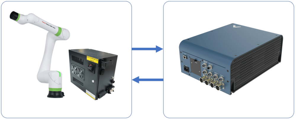
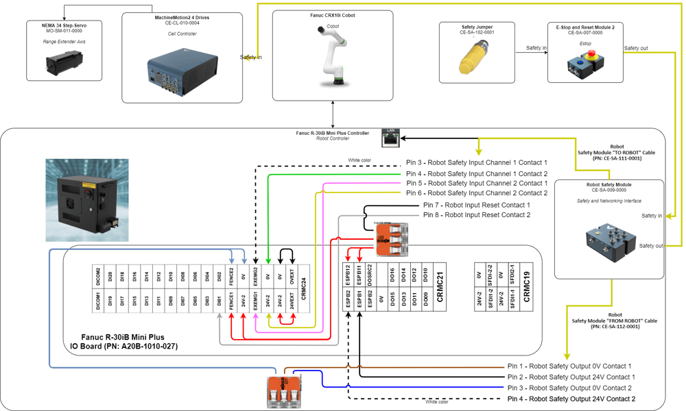
Vention’s Robot Safety Module is used to interface safety signals and Ethernet connection to the FANUC controller.
Below are the connections needed (area scanner optional; additional safety devices could be plugged in series to the E-stop module)
Safety behaviour
- In case of an E-stop (Vention or FANUC Pendant), or any other device that detects a dangerous situation on the Vention Safety Chain:
- Safe Behaviour:
- MachineMotion axis falls into STO
- FANUC CRX Falls into STO or SS1, as configured
- Recovery
- Pressing on the reset (blue) button will give power back to the MachineMotion and activate FANUC CRX safety signals from Robot Safety Module
- Safe Behaviour:
- In case of a reduced speed situation from the laser area scanner:
- Safe Behaviour:
- FANUC CRX will activate collision detection and slow down to collaborative speed
- MachineMotion is not influenced by this situation. This needs to be taken into account in the risk assessment. Axis will run at configured speed
- Recovery:
- If the laser area scanner is not able to detect a human everywhere where there is a danger, but can detect the entry points, then the laser scanner should be configured with manual reset. In this case, pressing the reset button will bring back the FANUC CRX to normal speed
- If the laser scanner is able to detect a human everywhere where there is a danger, then the laser area scanner can be configured with auto reset (to be determined and confirmed by risk assessment). In this case, if the laser area scanner does not detect a human in the workspace, the FANUC CRX will resume to full speed.
- Safe Behaviour:
Software installation
Note: The KAREL option is required to run any customer KAREL programs in FANUC robots. KAREL is a powerful programming language that allows you to access and control all aspects of the FANUC robot, except motion.
To install the MachineMotion V2 FANUC extension, perform the following steps:
- Insert the provided USB stick containing the MachineMotion V2 FANUC extensions into the USB port of your FANUC controller.
- In the FILE menu on the FANUC pendant click the FILE sub-menu.
- Press F5 [UTIL]
- Select 1 Set Device
- Select 6 USB DISK (UD1:)
- Press F2 [DIR] to open the directory subset popup.
- Click option 0 – Next until you reach the final page containing option 7. Directories.
- Select option 7. Directories to open the directory browser.
- Double click the directory option titled V.X.X.X (version number) to open the directory.
- Import Vention
.pcfiles:- Select option 8 * PC (all Karel p-code).
- Press F2 LOAD to load
VTN_*programs. - Wait for load to complete.
MachineMotion V2 setup
- Ensure that all motors are connected to their respective “Drive” ports and all I/O modules are connected to their respective “Control” ports. You can refer to the MachineMotion V2 User guide for more details
- Ensure that all safety devices are correctly connected and commissioned and that a risk assessment is completed and signed.
- Plug the MachineMotion V2 into a power outlet.
- Connect with an ethernet cable a laptop to the machine motion TO PC port.
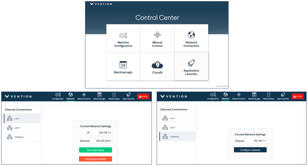
- Open a browser (i.e. Google Chrome) and navigate to http://192.168.7.2.
- Click on the “Machine Configuration” Icon, and configure all your Servo Axis in your system. Refer to the automation system diagram ASD to check your specific axis configuration.
- Configure the MachineMotion V2 Network Connection for the port connected to the FANUC controller.
For example, if LAN 1 is connected to the FANUC controller.- IP: 192.168.0.2
- Netmask: 255.255.255.0
-
Gateway: 192.168.0.1
Note: You can connect and interface with multiple MachineMotion V2 controllers on a shared subnet using an ethernet router or a ethernet switch.
Communication
TCP communication using the MachineMotion V2 FANUC extension
- Ensure that options R632 – KAREL and R648 – User Socket Messaging are installed on the CRX controller. Refer to Fanuc documentation for detailed instructions on how to install options, or reach out to Vention’s customer success team.
- The FANUC controller needs to be connected via Ethernet to the Vention MachineMotion. It is recommended to use the Vention Robot Safety module. See Figure 3.
-
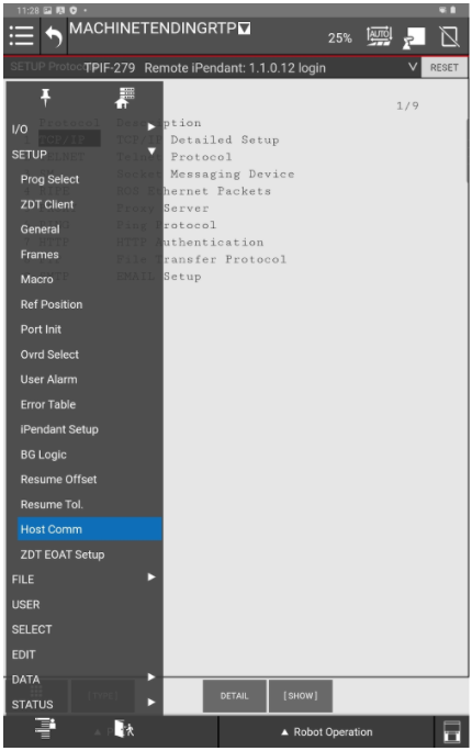
From the FANUC teach pendant go to the menu and navigate to the SETUP section and select Host Comm.
For additional information: Refer to the FANUC KAREL Reference Manual, section 12, procedure 12.1 for expanded detail on the steps below. This can be accessed via the FANUC Customer Resource Center.
- Select TCP/IP.
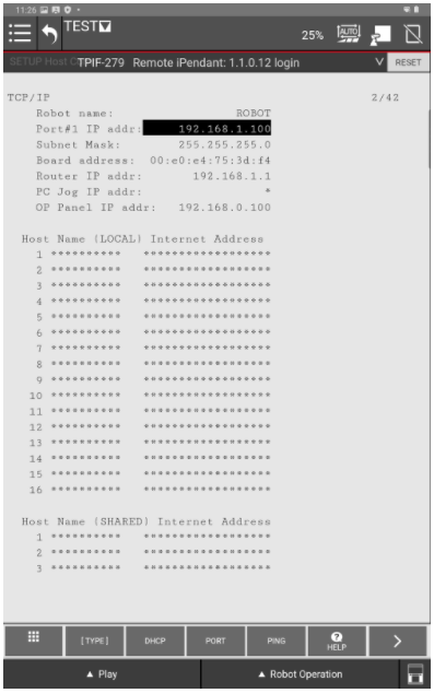
- Press DETAIL.
- Configure the FANUC controller’s network settings.
For example, if you used the suggested network configuration in the MachineMotion, you can use the following FANUC network configuration:- Port #1 IP addr:: 192.168.0.3
- Subnet Mask: 255.255.255.0
-
Router IP addr: 192.168.0.1 (The IP Address configured on the MachineMotion V2).
- Reboot the FANUC controller for the network configuration changes to take effect.
- Configure the Client Tag network parameters (
C1:, C2:, ...).
For additional information of to re-configure a client tag, see: Important note on FANUC ClientTag configuration.- From the FANUC teach pendant go to the menu and navigate to the SETUP section and select Host Comm.
- Double click SHOW and 2 Clients.
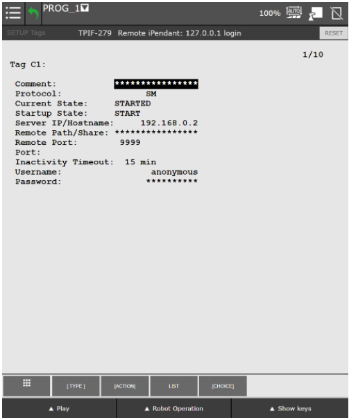
- Press C1:
- Protocol needs to be set to SM
- Enter for Server IP/Hostname Vention MachineMotion IP Address (Ex. 192.168.0.2)
- Remote port needs to be set to 9999
- For any additional MachineMotion’s, repeat the above steps for the additional connection tags (“C2:”, “C3:”, …).
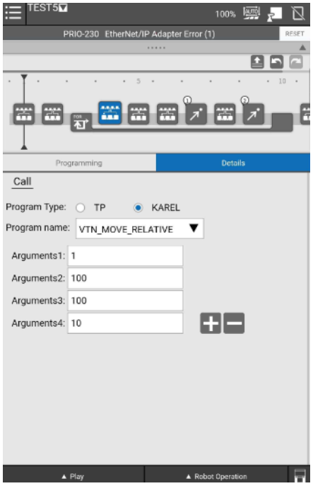
- To send commands to the MachineMotion V2:
- Create a TP program.
- All MachineMotion commands are sent by using the function block “CALL” compiled KAREL programs (
.pcfiles). - Enter the arguments of each MachineMotion V2 FANUC extension commands.
- All TP programs sending commands to the MachineMotion should start with calling
VTN_OPEN_CONNand should end withVTN_CLOSE_CONN.
Note: All Vention MachineMotion commands start with
VTN_
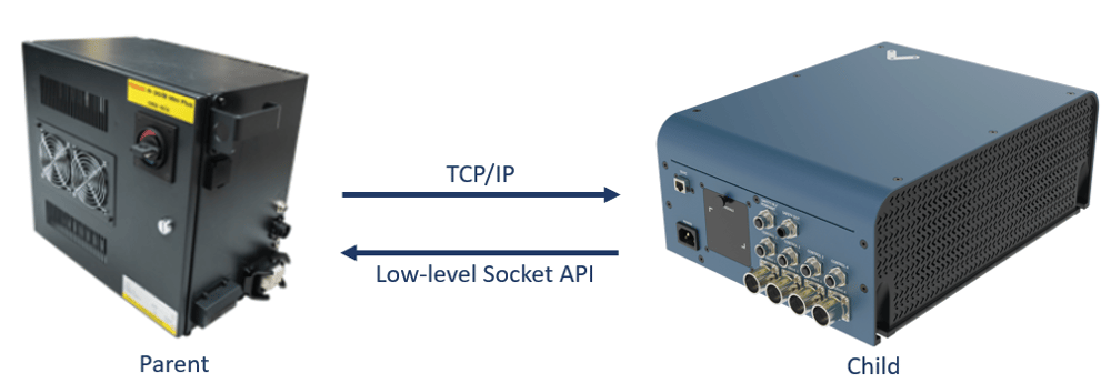
- Notes on FANUC-Vention communication via TCP/IP:
- The logic lives on the FANUC controller (parent); MachineMotion is the child controller.
- The FANUC controller sends commands to MachineMotion and waits for a response.
- E-Stop Behaviour: If an E-stop is triggered while running a Fanuc TP program calling MachineMotion commands, the last MachineMotion command will not be completed upon restart. It is then recommended to abort the TP program and restart it after recovering from an E-Stop.
MachineMotion V2 FANUC extension commands
The following commands provide an interface to control the MachineMotion V2 from within FANUC TP programs. Errors occurring within these programs will appear with error code 148. For additional help with debugging, see Debugging and viewing
VTNlog messages. For additional information on FANUC ClientTags, see Important note on FANUC ClientTag configuration.
| Command name | Description | Argument 1 | Argument 2 | Argument 3 | Argument 4 | Argument 5 |
|---|---|---|---|---|---|---|
| VTN_OPEN_CONN | This function opens the connection with the Vention MachineMotion. This function must be called before any other actions with a given MachineMotion V2 connection. | Connection String Index (1, 2, …) | n/a | n/a | n/a | n/a |
| VTN_CLOSE_CONN | This function closes the connection with the MachineMotion V2. Upon successfully closing the connection, all axes will stop. | Connection String Index (1, 2, …) | n/a | n/a | n/a | n/a |
| VTN_HOME_AXIS | This function is used to home an axis. This function will wait until the homing is completed before exiting. | Connection String Index (1, 2, …) | Axis Number (1 to 4) | n/a | n/a | n/a |
| VTN_MOVE_ABSOLUTE | This function is used to move the axis to an absolute position. This function will wait until the move is completed before finishing. | Connection String Index (1, 2, …) | Axis Number (1 to 4) | Absolute position [mm] | Speed [mm/s] | Acceleration [mm/s^2] |
| VTN_MOVE_RELATIVE | This function is used to move the axis to a relative position. This function will wait until the move is completed before exiting. | Connection String Index (1, 2, …) | Axis Number (1 to 4) | Relative position [mm] | Speed [mm/s] | Acceleration [mm/s^2] |
| VTN_MOVE_CONTINUOUS | This function is used to move the axis with constant speed. This function will send the command to the axis and immediately exit. | Connection String Index (1, 2, …) | Axis Number (1 to 4) | Speed [mm/s] | Acceleration [mm/s^2] | n/a |
| VTN_STOP_MOVE_CONTINUOUS | This function is used to stop a continuous move. This function will wait until the axis is stopped before exiting. | Connection String Index (1, 2, …) | Axis Number (1 to 4) | Deceleration [mm/s^2] | n/a | n/a |
Important note on FANUC ClientTag configuration
Due to the FANUC controller’s handling of ClientTags, it is possible that when using a re-configured ClientTag the FANUC controller will refer to old network configuration parameters (IP, Port, etc). To resolve this issue refer to the section in the FANUC controller manual titled “Setting up a ClientTag” or follow the procedure below.
Re-configuring a FANUC controller ClientTag
- On the FANUC controller teach pendant, press MENU.
- Select SETUP.
- Press F1, [TYPE].
- Select Host Comm.
- Press F4, [SHOW].
- Select Clients.
- Select the Tag you wish to setup for socket messaging and press F3, [DETAIL].
- Move to the Protocol Name option and press F4, [CHOICE] and select SM (Socket Messaging).
- Move the cursor to the Startup State item:
- Press F4, [CHOICE] and select UNDEFINE
- Press F4, [CHOICE] and select DEFINE
- Move to the Server IP/Hostname option, press Enter and type in the IP address of the MachineMotion V2 controller.
- Perform the following steps. If an error occurs in either step, reboot your FANUC controller and resume from here.
- Press F2, [ACTION] and select STOP.
- Press F2, [ACTION] and select UNDEFINE.
- Move to the Port option, press enter and type in
9999. - Press F2, [ACTION] and select DEFINE.
- Press F2, [ACTION] and select START.
- Reboot the FANUC controller.
- Upon reboot, the ClientTag should be ready for use.
Debugging and viewing VTN log messages
In troubleshooting situations it may be useful to examine internal program logs from the
VTN_*KAREL programs. To do so, perform the following procedure to access the FANUC controller USER log area.
- On the FANUC controller teach pendant, press MENU.
- Select User
- A list of log messages from previously run programs will appear.