

Datasheet
Updated: Tuesday, June 20th 2023
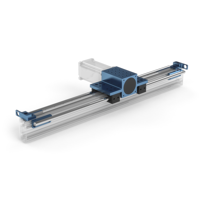
Rack and Pinion Actuator
Contents
Overview
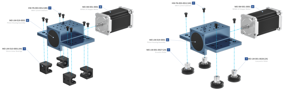
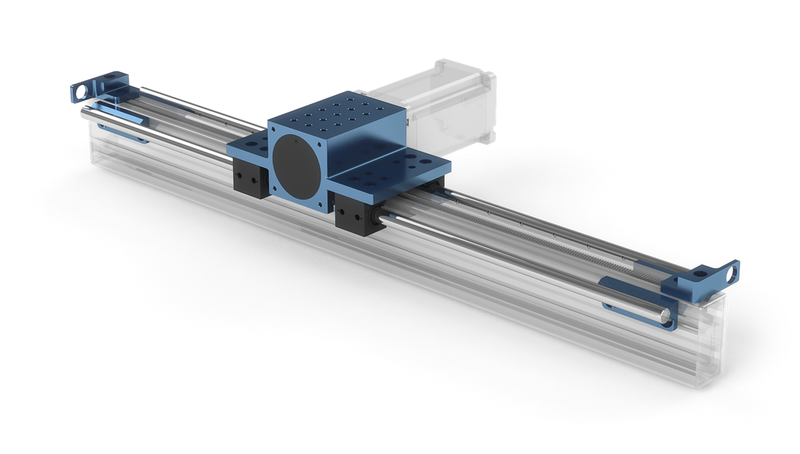
The assembly of the rack and pinion consists of installation of the rack segments into the extruded aluminum T-slot and the pinion housing assembly mounted on linear bearings or rollers. The pinion housing assembly (MO-LM-019-0001) allows for any combination of Vention’s NEMA 34 stepper motors and/or Vention’s 5:1 gearbox to drive the actuator. With the 40:1 force to torque ratio of the rack and pinion and any combination of powertrain parts, multiple levels of force can be achieved. The housing also features mounting holes that interface perfectly with extruded aluminum T-slots, assembly plates, or gantries. End stops allow for installation of any Vention M18 sensors and also mount directly to the rack. Finally, two rack segment lengths are avaliable and can be used in combination to create your desired rack length.
Applications
There are several applications for rack and pinion systems. One ideal use is in z-axis applications for lifting heavier loads at a fast pace, such as a Vention 3 or 4 axis palletizer’s z-axis. Another application where a rack and pinion system excels in long range extenders such as a cobot range extender.
Technical Specifications
Powertrain Combinations
| Max Force - Motor with Rack and Pinion [N] | Max Force - Motor and Gearbox with Rack and Pinion [N] | |
| MO-SM-011-0000 | 350 | 1000 (Actuator Limited) |
| MO-SM-012-0000 | 200 | 990 |
| MO-SM-013-0000 | 105 | 505 |
Force versus Speed
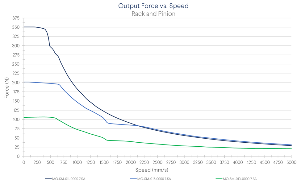
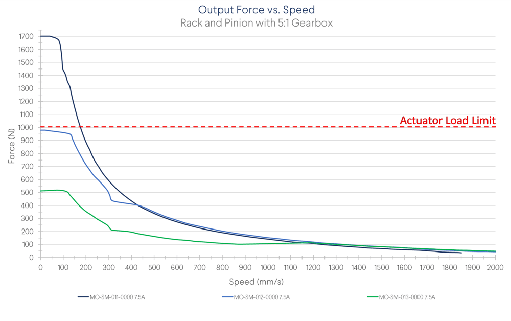
Note: During MachineMotion’s boot up sequence, the holding force is momentarily 65% of its rated value. Please keep in mind when using in vertical and/or angled applications.
Specifications
| Maximum Speed (mm/s) | 3000 (without gearbox) 1563 (with gearbox) |
| Axial Load Capacity (N) | 1000 |
| Pinion Pitch Diameter (mm) | 50 |
| Displacement Ratio (mm/turn) | 157.08 |
| Linear Force / Torque Ratio (N/Nm) | 40 |
| Repeatability including backlash (mm) | ±0.25 |
| Total Backlash (mm) | 0.25 |
| Motor Compatibility | All NEMA 34, 14mm shaft, 5mm Key |
Assembly Instructions
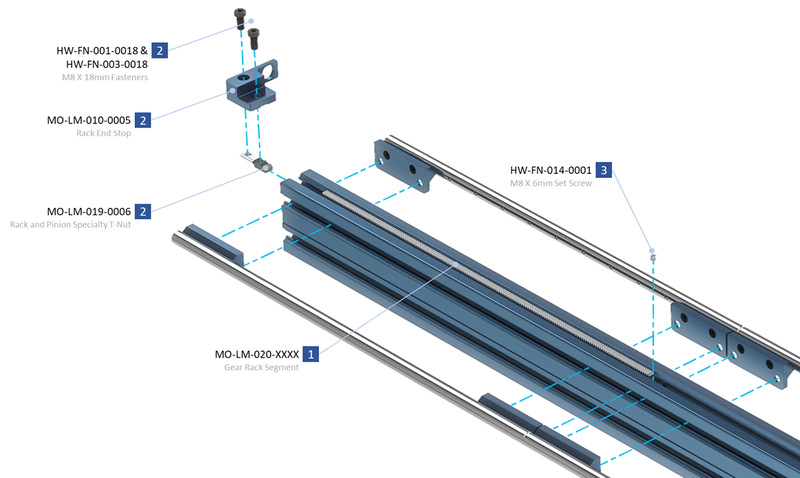
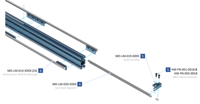
- Slide the rack segments into the aluminum extrusion T-slots as shown. This can be done by hand or by using the rack installation tool that comes with your order
- Install the end stop to the first segment using the included specialty T-Nut to properly support the end of the rack segment. Make sure that the specialty T-nut and rack end are butted up together before tightening the end stop fasteners.
- Secure the other end of the rack segment using the included set screw to jam the segment in place.
- Slide in the next rack segments as required using the rack installation tool, HW-TL-004-0001 to slide it in.
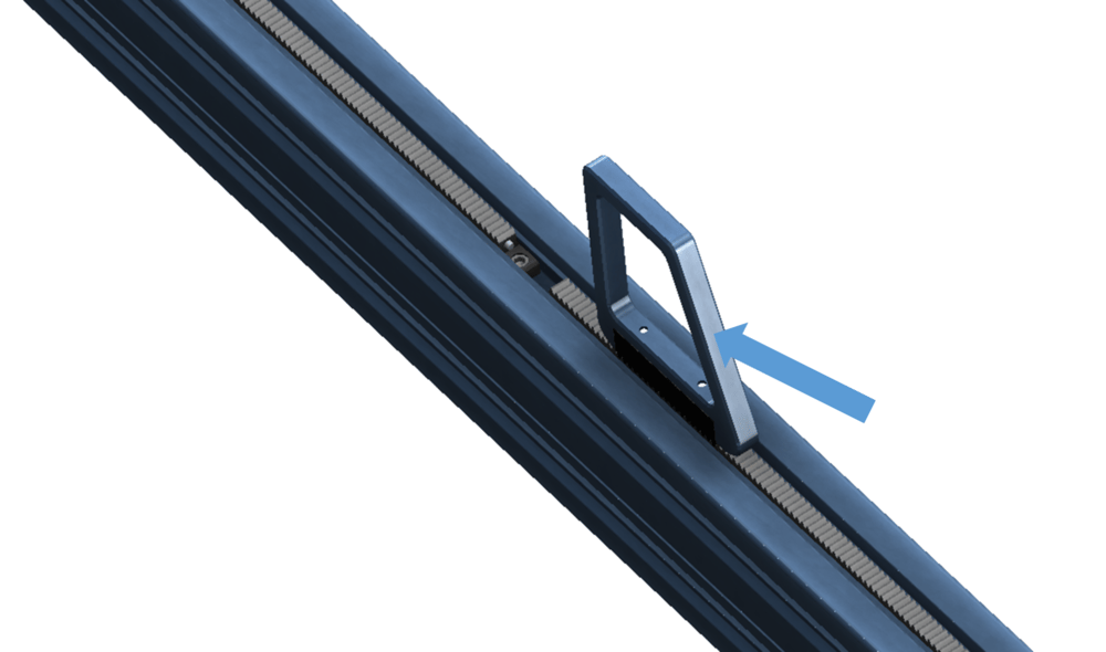
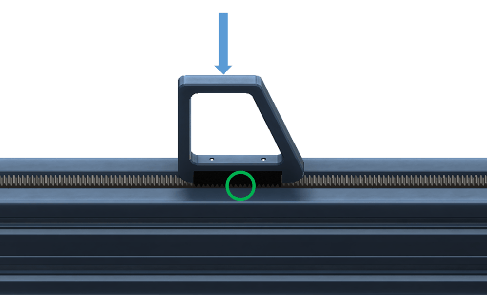
- Once the rack segments are close, some force may be required to properly engage the segments. If necessary, adjust the set screw in step 3 so that the fit between the two segments is snug. We recomend using a soft blow hammer on the angled side of the installation tool and tapping the segment until the faces are butted together:
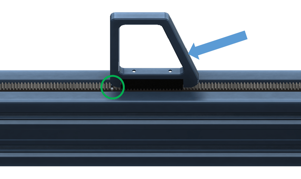
- ensure that the teeth are properly spaced by placing the teeth of the tool over the joint of the two rack segments. Optimal alignment can be achieved by tapping the top of the rack installation tool with a soft blow hammer to force the teeth into the correct spacing as shown (note the green circle represents the location of the joint):
- Once all segments are in place, install the end stop to the last rack segment using a HW-FN-003-0018 instead of a set screw.
- As received, the pinion housing assembly is pre-assembled
- Attach the Rack and Pinion Housing to the extrusion via one of Venion’s linear guides such as the Vention 16mm linear guide rails (Assembly requires shaft MO-LM-014-XXXX and bearings MO-LM-010-0001) or the Vention roller wheels (Assembly requires two eccentric wheels MO-LM-001-0027 and two concentric wheels MO-LM-001-0028).
- Once the housing is mounted, run the housing along the axis by hand ensuring that it is smooth and the pinion does not jam at any joint.
- Mount the intended powertrain parts such as the 5:1 gearbox and motor to the housing input and connect any extrusions or assembly plates to the sides or top of the housing.
- Assembly is complete.
Additional Assembly Tips
Wait to tighten the fasteners of the linear shaft until the pinion housing is mounted on the linear guide. Tighten the fasteners only as you move along the actuator with the pinion housing, allowing the guides to self align with the assembly.