Rack and Pinon Actuator
Overview
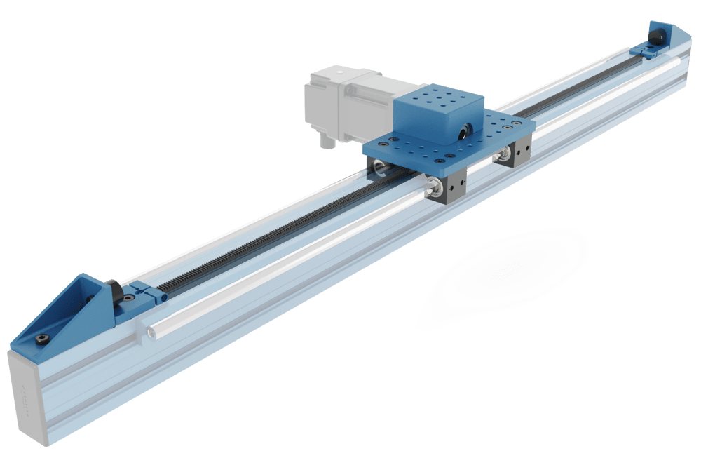
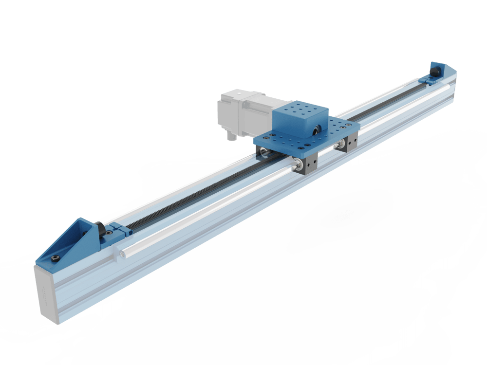
The rack and pinion actuator consists of rack segments installed into the extrusion frame and the pinion housing assembly mounted onto the frame through a set of linear guide bearings. The pinion housing assembly (MO-LM-019-0000) allows for any combination of Vention’s NEMA 34 stepper motors and/or Vention’s power transmission components to drive the actuator. With choices in motor type as well as the use of a gearbox, multiple levels of force can be achieved. The housing also features mounting holes that interface perfectly with Vention’s frame connectors and assembly plates. Two rack segment lengths (540mm and 810mm) are available and can be used in combination to create an actuator of any desired rack length.
This datasheet provides technical specifications for Vention’s Rack & Pinion Actuator V2. For details on Vention’s Rack & Pinion Actuator V1, refer to the ‘Documentation for Previous Product Versions’ section at the bottom of this page.
Applications
There are several applications for rack and pinion systems. One ideal use is in high speed lifting operations, such as a Vention’s 3 or 4 axis palletizer z-axes. Another application where a rack and pinion system excels is in long range extenders or any application where actuation stroke of 3.3m or larger is needed.
Technical Specifications
Power Transmission Combinations
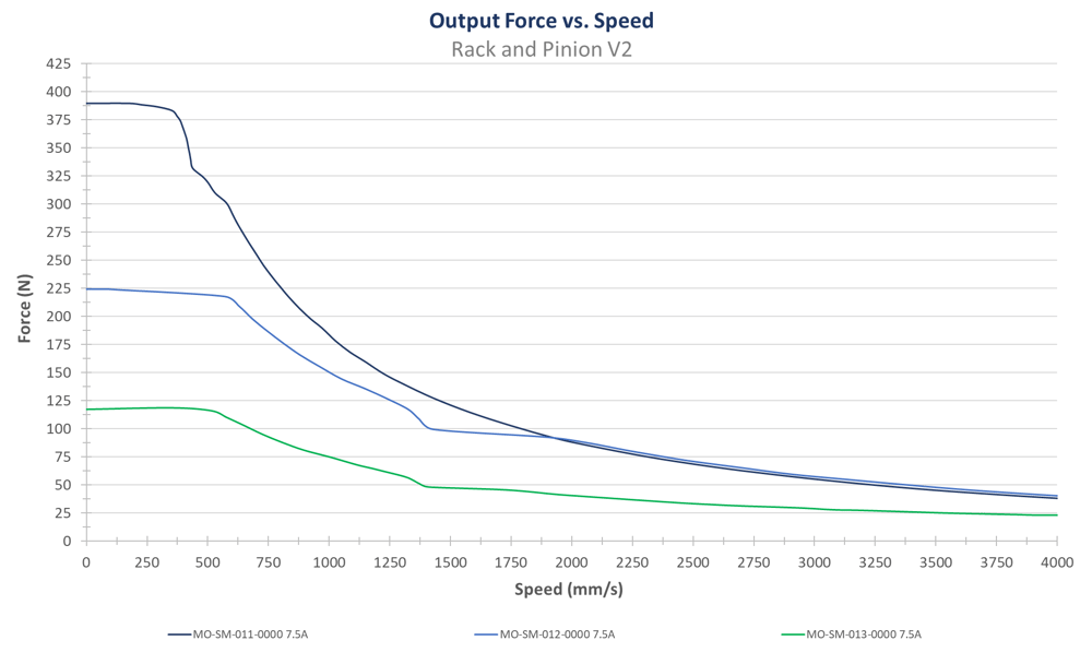
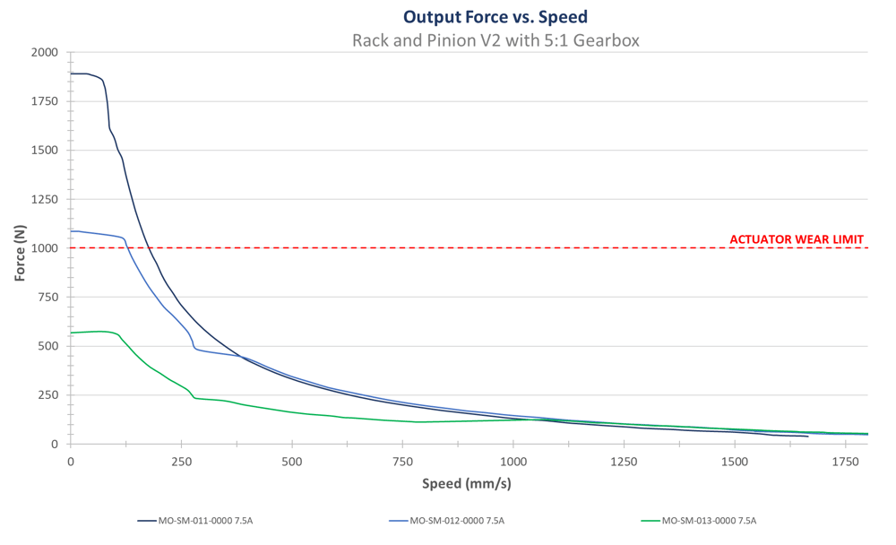
| Max Force - Motor Only [N] | Max Force - Motor and Gearbox [N] | |
| MO-SM-011-0000 | 385 | 1000 (Limited by actuator wear rate) |
| MO-SM-012-0000 | 220 | 1000 (Limited by actuator wear rate) |
| MO-SM-013-0000 | 115 | 570 |
Force versus Speed
Note:
- During MachineMotion’s boot up sequence, the holding force is momentarily 65% of its rated value. Please keep in mind when using in vertical and/or angled applications.
- These performance curves are made with our motors and controller at steady state conditions. Using others motors or controllers will have different behavior therefore performance and reliability cannot be guaranteed.
Specifications
| Maximum Speed (mm/s) | 4000 (without gearbox) 1750 (with gearbox) |
| Axial Load Capacity (N) | 1000 |
| Pinion Pitch Diameter (mm) | 45 |
| Displacement Ratio (mm/turn) | 141.37 |
| Repeatability including backlash (mm) | ±0.3 |
| Total Backlash (mm) | 0.25 |
| Motor Compatibility | All NEMA 34, 14mm shaft, 5mm key |
Assembly Instructions
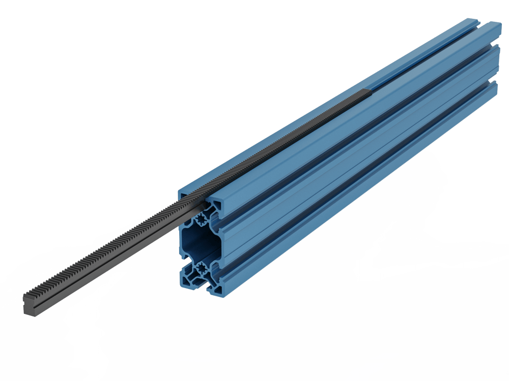
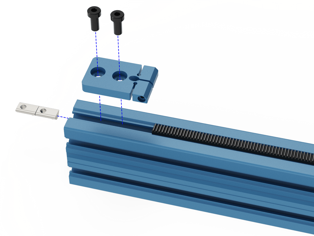
- Slide the rack segments into the aluminum extrusion T-slots as shown. This can be done by hand or by using the rack installation tool, HW-TL-004-0001, that comes with your order.
- Install the Rack Compression Block at the end of the first segment using the included 16mm long M8 bolts (HW-FN-003-0016) ant T-Nuts (HW-FN-002-0001). For now, leave the M6 (HW-FN-013-0025) set screw and M4 clamping bolt (HW-FN-010-0030) loose or uninstalled; they will be covered in a future step.
- Slide in the subsequent rack segments until all segments have been installed. This can be done by hand or by using the rack installation tool, HW-TL-004-0001, and a soft blow hammer if there is any resistance.
- Once all segments have been installed, mount to second Rack Compression Block as shown, again using 16mm M8 bolts and T nuts.
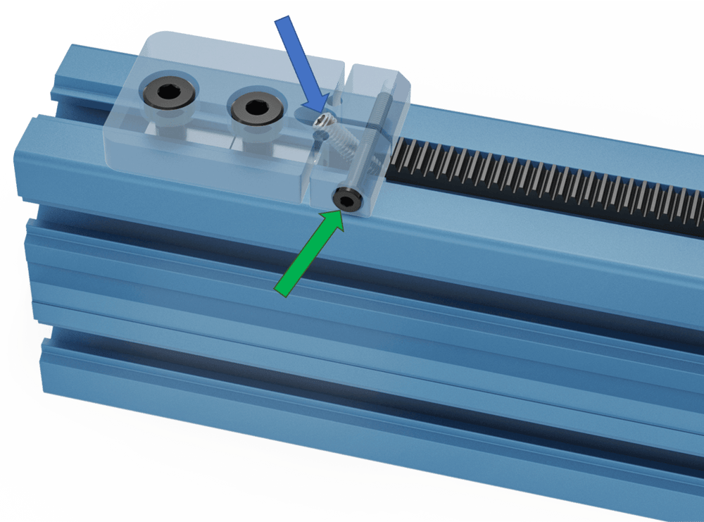
- Once the compression block is fixed in place, install the M6 set screws, HW-FN-013-0025 (blue arrow) in each compression block. Additionally, install the M4 clamping bolt, HW-FN-010-0030 (green arrow) in the side of both compression blocks. The M4 should be snug but not tightened. Begin tightening both M6 set screws by even amounts on both compression blocks until all slack in the rack segments has been absorbed. Finally, tighten the M4 clamping bolts to prevent the M6 set screws from loosening.
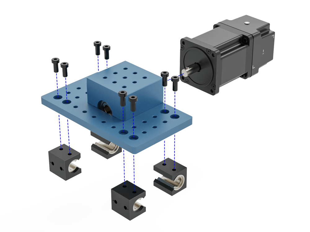
- As received, the Housing and Pinion Assembly is already pre-assembled.
- Mount the intended power transmission components such as the 5:1 gearbox and motor to the housing input shaft and attach the Rack and Pinion Housing to the extrusion via one of Vention’s linear guides such as the Vention 16mm linear guide rails (Assembly requires shaft MO-LM-014-XXXX and bearings MO-LM-010-0001) or the Vention roller wheels (assembly requires two eccentric wheels MO-LM-001-0027 and two concentric wheels MO-LM-001-0028). When installing the housing on linear bearings, ensure you use 12mm long M8 fasteners (HW-FN-003-0012).
- Notes:
- The bearings should be mounted on the rail before attaching the housing. The image below does not show the rails for visual clarity.
- When installing motors, apply a small amount of grease to the motor shaft so that it is lightly coated. This will reduce the possibility of fretting corrosion occurring during operation, making future removal easier.
- Moreover, do not use excessive force (hammering, prying or using screws to “push” the motor) to install the motor.
- Once the housing is mounted, run the housing along the axis by hand ensuring that it is smooth and the pinion does not jam at any joint.
- Mount external home and end position sensors as well as bump stop HW-BP-001-0004.
- Be sure to apply grease to the racks and cycle the actuator back and forth by hand, ensuring the grease is distributed and coating the rack teeth. For more instructions on how to lubricate the actuator see the maintenance instructions here.
- Assembly is complete.
Additional Assembly Tips
For custom length rack and pinions, the rack segments can be cut with a hack saw or grinder. If this is done, place the rough cut end at the very end of the actuator contacting the compression block so that the rough cut does not affect the meshing of the gear racks and pinion.