20mm Profile Guide Rails
Contents
- Overview
- Applications
- Technical Specifications
-
Assembly Instructions
- MO-LM-049-0001, Fixed Mount 20mm Series Profile Guide Bearing Carriage
- MO-LM-049-0003, XL Extrusion Swivel Mount 20mm Series Profile Guide Bearing Carriage
- Grease Fitting Installation on MO-LM-049-0001 & MO-LM-049-0003
- MO-LM-049-XXXX, 20mm Series Profile Guide Rail Assembly
- Mounting Bearings on Rails
- Maintenance
Overview
Vention’s 20mm profile guide rails push the boundaries of load capacity and life expectancy previously available. With this bearing system, higher payload applications are possible with fewer bearings. This reduces installation complexities, improves system reliability, and eases maintenance.
The bearings are also sealed on all faces, making them suitable for environments where the round rail bearing systems cannot function.
The guide rail system has two bearing styles available. MO-LM-049-0001 is a rigidly mounted bearing that is compatible with all of Vention’s standard extrusions and linear guide accessories with the exception of 247.5 x 247.5mm extrusions (ST-EXT-011-XXXX). For the XL (247.5 x 247.5mm) extrusions, the other bearing mount assembly, MO-LM-049-0003, must be used. Both bearing types can be used with any combination of the rail assemblies, MO-LM-049-XXXX, which are butt-joinable and also available in 6 lengths from 360mm to 3330mm to accommodate a variety of length requirements.
Advantages of this system include smooth and precise guiding, high rigidity and payload, long bearing life, high versatility, and strong environmental protection. Read on to learn the specifics of this linear guiding system.
Applications
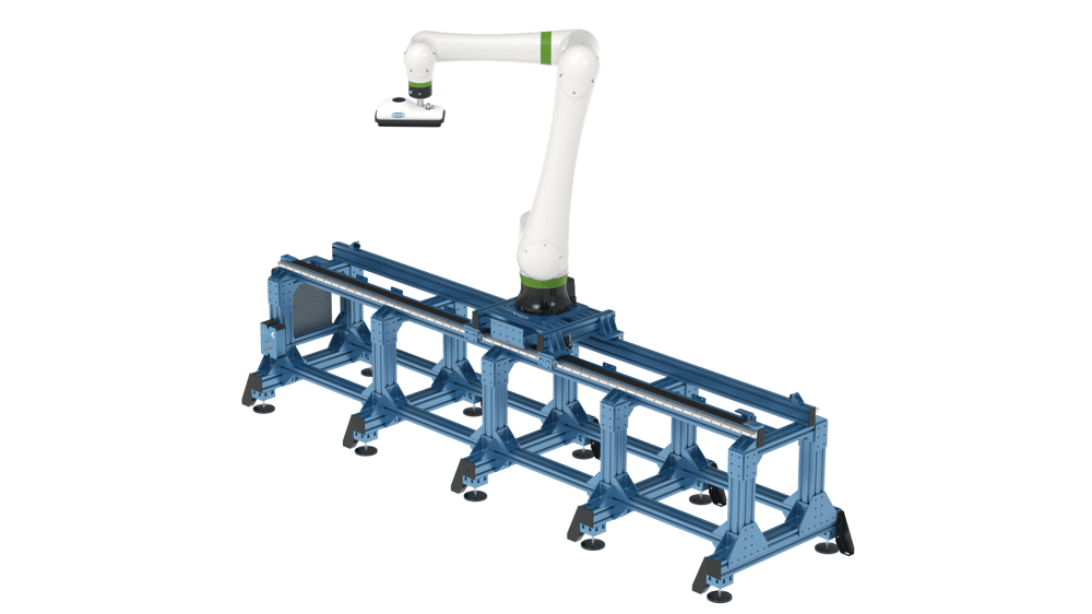
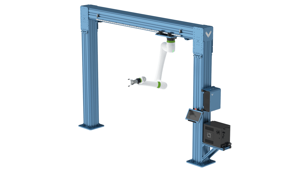
The applications for the new 20mm profile guide bearing system share some common parameters. The bearings are well suited for heavy duty, high rigidity applications where external guiding is necessary. The bearings are particularly well suited for large gantry systems or high payload cobot range extenders.
The 20mm profile guides are also the only bearings that can be mounted directly to the XL extrusion system by using the XL Extrusion Swivel Mount 20mm Series Profile Guide Bearing Carriage.
Technical Specifications
General Specs
The general specifications of the product can be found in the table below, while more detailed information about dimension, weight, and load capacity can be found in the following tables.
| Max Rated Speed | 10 m/s |
| Frictional Loss (New) | 8 N |
| Frictional Loss (After break-in) | 5 N |
| Binding Ratio | >10 |
| Grease Capacity | 5ml |
| Maintenance Interval | 100 km |
| Possible Configurations (MO-LM-049-0001) | 1, 2, 4+ bearings |
| Possible Configurations (MO-LM-049-0003) | 4+ bearings |
Weights and Dimensions
| Name | Part Number | Weight (kg) | Length (mm) |
|---|---|---|---|
| Fixed Mount 20mm Series Profile Guide Bearing Carriage | MO-LM-049-0001 | 0.607 | 90 |
| XL Extrusion Swivel Mount 20mm Series Profile Guide Bearing Carriage | MO-LM-049-0003 | 1.195 | 88 |
| 20mm Series Profile Guide Rail Assembly, 360mm | MO-LM-049-0360 | 0.924 | 360 |
| 20mm Series Profile Guide Rail Assembly, 585mm | MO-LM-049-0585 | 1.437 | 585 |
| 20mm Series Profile Guide Rail Assembly, 855mm | MO-LM-049-0855 | 2.104 | 855 |
| 20mm Series Profile Guide Rail Assembly, 1530mm | MO-LM-049-1530 | 3.746 | 1530 |
| 20mm Series Profile Guide Rail Assembly, 2295mm | MO-LM-049-2295 | 5.594 | 2295 |
| 20mm Series Profile Guide Rail Assembly, 3330mm | MO-LM-049-3330 | 8.108 | 3330 |
Loads and Moments
The table below contains all of the force and moment ratings for the bearing system. The maximum static load, Co, cannot be exceeded at any point as this will permanently deform the bearing element. The maximum dynamic load, C10, represents a loading condition where 90% of the bearings will survive (10% failure rate) at a travel distance of 100km. These values should be used for reference only as most applications travel much farther distance than 100 km and therefore will need to have lower applied forces to the bearings. Consult our application engineering team for help with determining the life of your system.
| Direction | Maximum Static Load (Co) | Maximum Dynamic Load (C10) |
|---|---|---|
| Fx | 34.3 kN | 27.4 kN |
| Fy | 34.3 kN | 27.4 kN |
| Fz | 34.3 kN | 27.4 kN |
| Mx* | 370 Nm | 295 Nm |
| My* | 350 Nm | 280 Nm |
| Mz* | 350 Nm | 280 Nm |
*Note: Only MO-LM-049-0001 is capable of taking moment loads directly. MO-LM-049-0003 has a spherical bearing to allow for angular alignment on the XL extrusions and therefore cannot take moment loads directly. Therefore MO-LM-049-0003 can only be used in configurations of 4+ bearings.
As an example, mounting a CRX25 on a four bearing system using XL extrusion and MO-LM-049-0003 bearings will have approximately 4 years of expected L10 life and 12 years MTBF (mean time between failures) under the following conditions:
- 16 hours/day, 5 days/week, 52 weeks/year
- 3+ cycles per minute defined by:
- 2m stroke
- 1m/s max speed
- 2m/s2 acceleration
- Semi retracted robot arm during motion (CGx/y located within 400mm of the base)
For help analyzing you application’s life and validating bearing selection, consult our application engineering team.
Assembly Instructions
Below the assembly instructions are broken up into section for the bearings, the rails, and how to join them together.
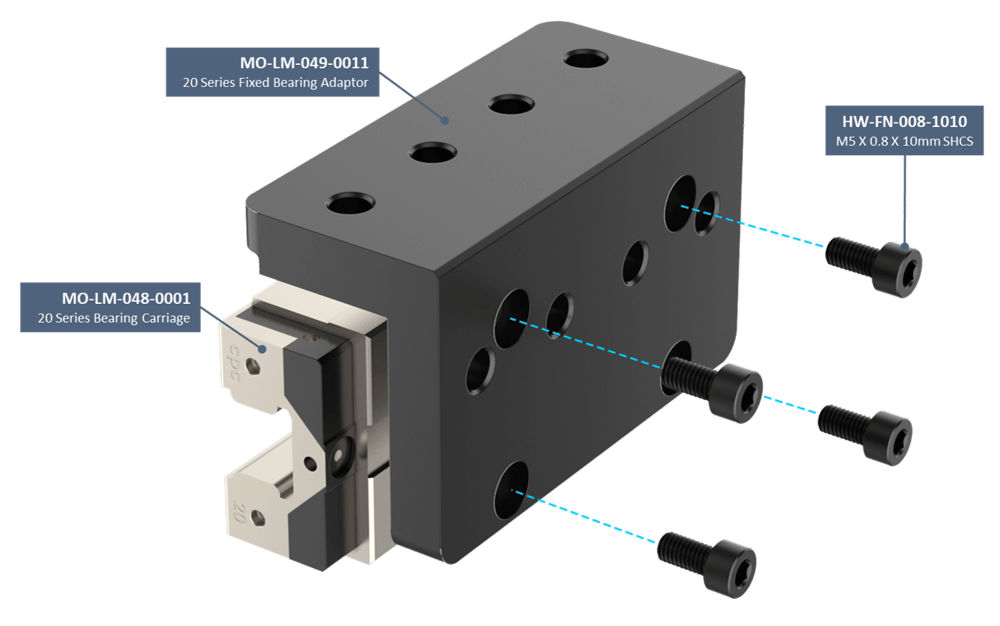
MO-LM-049-0001, Fixed Mount 20mm Series Profile Guide Bearing Carriage
To assemble the Fixed Mount 20mm Series Profile Guide Bearing Carriage follow the following steps:
1. Open the bearing packaging. Remove the vacuum sealed plastic wrapping on the bearing but keep the hard plastic insert installed in the bearing! That insert is needed for installation of the bearing on the rail. Take care to keep the bearing clean and wipe away any anti-corrosion oil on the mounting faces.
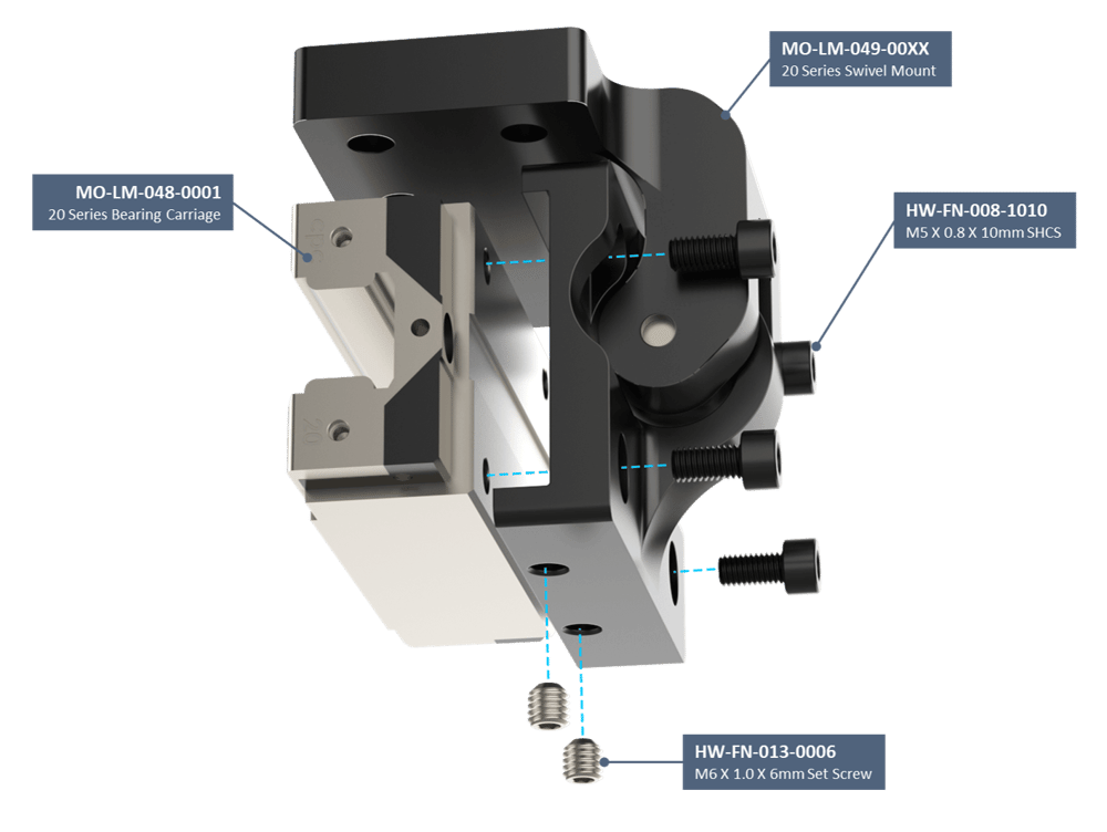
2. Unwrap the bearing mount and locate the four M5 standard head fasteners included in the box.
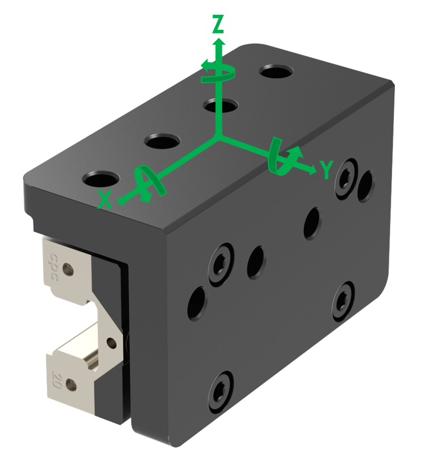
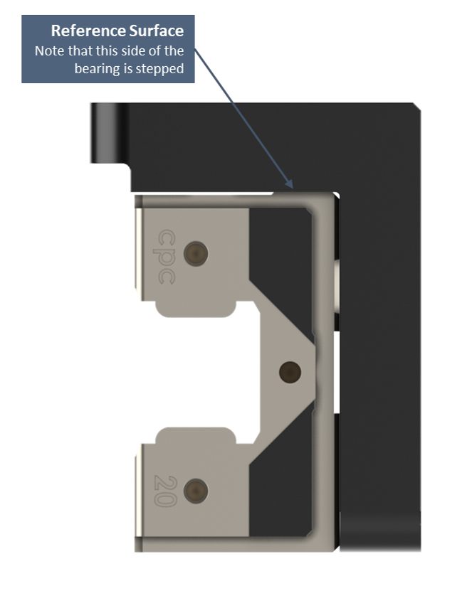
3. Orient the bearing so that the reference surface of the bearing (the side of the bearing with the ground surface that is stepped) is towards the upper-inner corner of the aluminum mounting block. See the image below for reference and notice that the stepped side is on top.
4. Align and install the M5 bolts through the counterbores of the mounting block with the threaded holes in the bearing carriage. Keep the bolts loose at this point.
5. While pushing the reference surface of the bearing into the face of the bearing mount so that there is no gap, tighten the four M5 bolts to lock the bearing in place.
6. Torque each M5 bolt to 10-11Nm.
7. Assembly is complete.
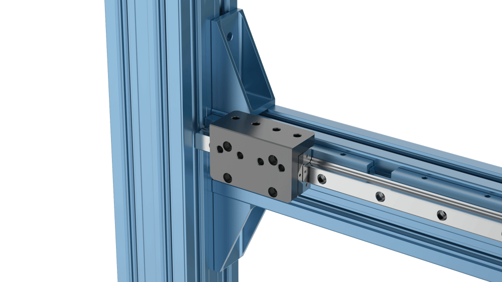
MO-LM-049-0003, XL Extrusion Swivel Mount 20mm Series Profile Guide Bearing Carriage
Assembly of the XL Extrusion Swivel Mount 20mm Series Profile Guide Bearing Carriage involves the following steps:
1. Open the bearing packaging. Remove the vacuum sealed plastic wrapping on the bearing but keep the hard plastic insert installed in the bearing! That insert is needed for installation of the bearing on the rail. Take care to keep the bearing clean and wipe away any anti-corrosion oil on the mounting faces.
2. Unwrap the bearing mount and locate the four M5 standard head fasteners and two M6 set screws included in the box.
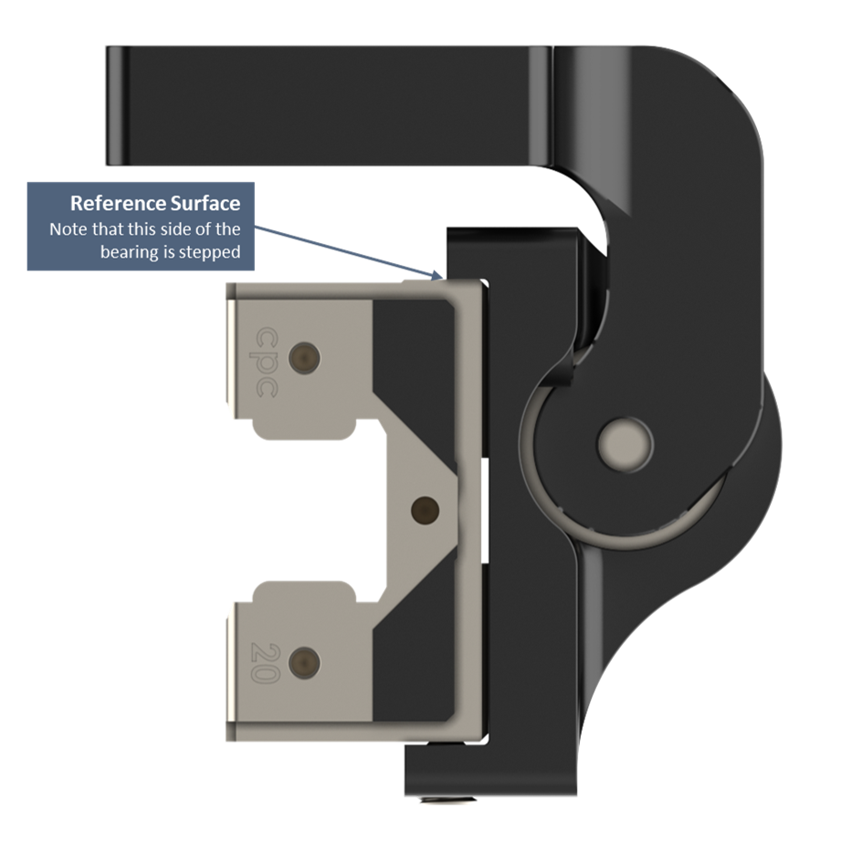
3. Orient the bearing so that the reference surface of the bearing (the side of the bearing with the ground surface that is stepped) is towards the upper-inner corner of the mounting assembly. The side without the reference surface should be next to the two holes for the M6 set screws.
4. Align and install the M5 bolts through the counterbores of the mounting block with the threaded holes in the bearing carriage. Keep the bolts loose at this point.
5. Install the two M6 set screws in the bottom of the bearing mount and lightly tighten them so that reference surface of the bearing is forced against the upper-inner corner of the mounting assembly. The set screws should only be lightly tightened at this point (1-2Nm).
6. Tighten all the M5 bolts and M6 set screws to 10-11Nm.
7. Assembly is complete.
Grease Fitting Installation on MO-LM-049-0001 & MO-LM-049-0003
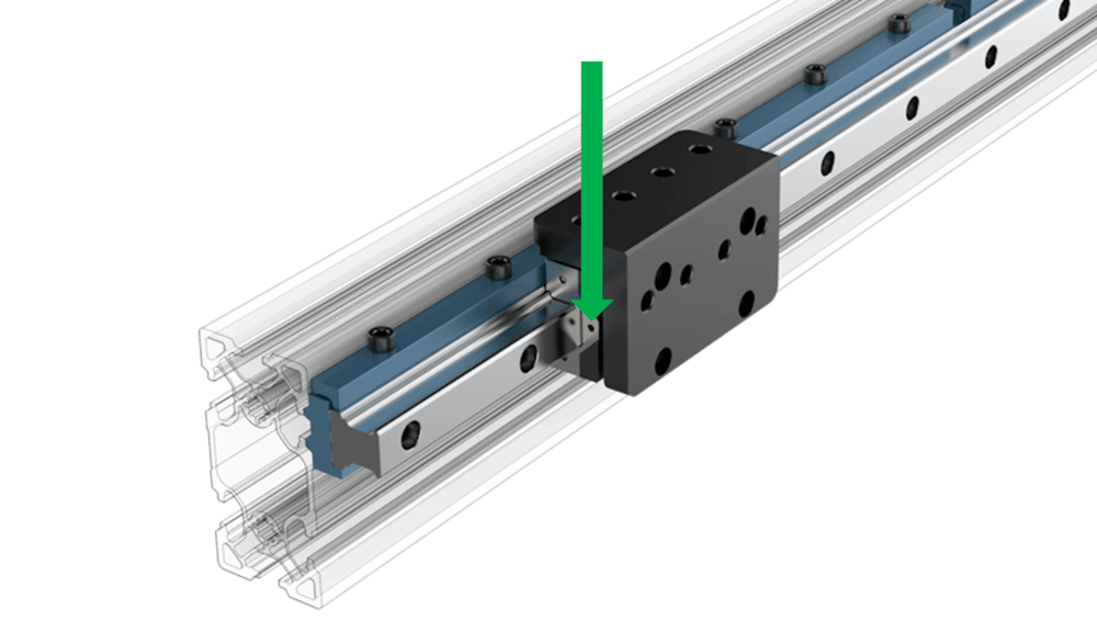
The bearing comes in the box with M3 grease fittings separate from the bearing block. To install the fitting, remove the M3 set screw in the location indicated by the arrow:
The grease fitting can be threaded into the open port. The Vention 14oz Grease Gun Kit comes with the fitting to connect to the grease fittings on these bearings.
Alternatively, the set screw can be removed at each lubrication cycle and grease injected directly in the hole using a needle style dispenser. The Vention 14oz Grease Gun Kit comes with the necessary needle style dispenser.
MO-LM-049-XXXX, 20mm Series Profile Guide Rail Assembly
Assembly of the linear guide rails will depend on your application and what the rails are mounted to. First, the instructions for mounting a single rail using the rail mounts will be covered. The following sections will go over more advanced installations involving butt-joining and shimming processes. However, first read these general warnings to help you avoid any assembly issues:
1. In assembly situations where the end of the rail is within 90mm of an obstruction such as another extrusion or even the pulley block of an actuator such as MO-LM-016-XXXX, it is important to pre-mount the bearings on the rails before installing them. This is because the bearing will be blocked from installation after the rail is mounted.
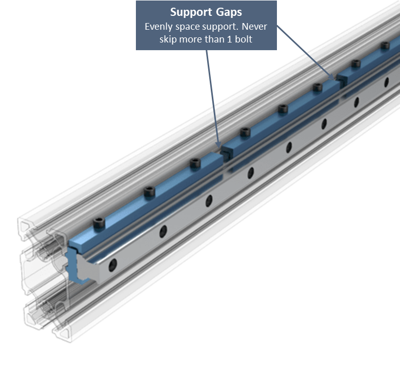
2. Most of the rail lengths do not have perfectly continuous supports. The gaps between supports are normal but the installation should be done such that there is never more than one bolt skipped between supports.
3. For larger gantry system where guides are mounted on separate extrusions, refer to the Vention Linear Axis Alignment Procedure technical document for instructions on how to align the frame to satisfy the product requirements.
Rail Mounts
To mount a 20mm Series Profile Guide Rail to an extrusion frame, follow these instructions:
1. Locate the box containing the linear guide rails.
2. The rails will be in a vacuum sealed plastic wrapping with anti-corrosion oil. Unwrap the rails and wipe them clean. Note: these rails can rust if no oil or grease is present on them so if they will be sitting unused be sure to apply a thin layer of grease on the rail.
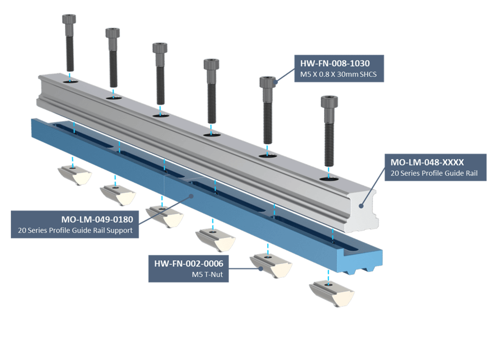
3. Locate the rail supports, MO-LM-049-0180, and the associated hardware, M5 x 30mm bolts and M5 t-nuts.
4. Orient the rail so that the reference face of the rail support is on the bottom. It is recommended to pre-install the T-nuts and bolts onto the guide rail by threading them together two revolutions of the bolt. It is also possible to install the t-nuts in the extrusion first then attach the bolts afterwards if desired but the pre-installation method is faster.
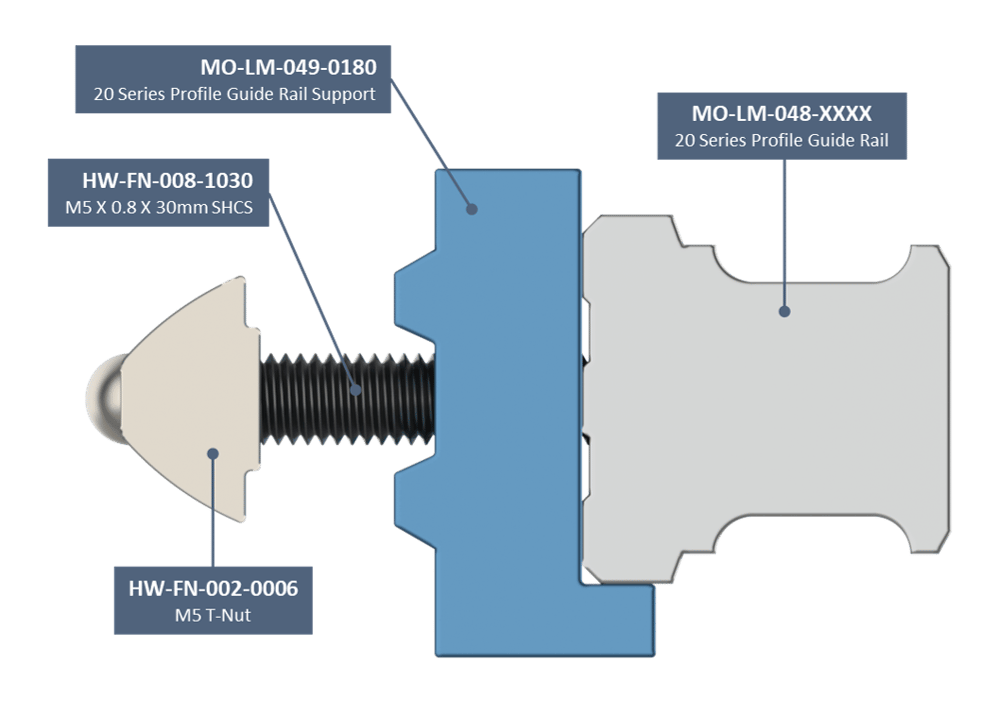
5. Slide the assembly into the end of the extrusion and move it to its final position. Screw in the the mounting bolts until snug but not tight.
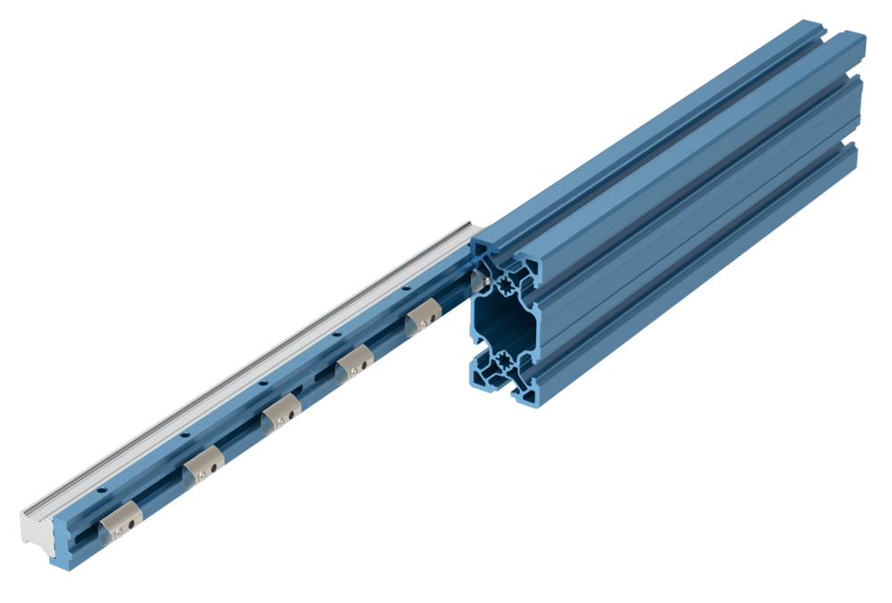
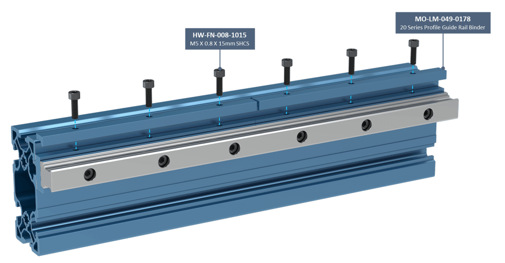
6. Locate the binder plates, MO-LM-049-0178, and their associated hardware, M5 x 15mm bolts.
7. Install binder plates on each rail support section. Lightly tighten both the binder plate and rail bolts to 1-2Nm as you go.
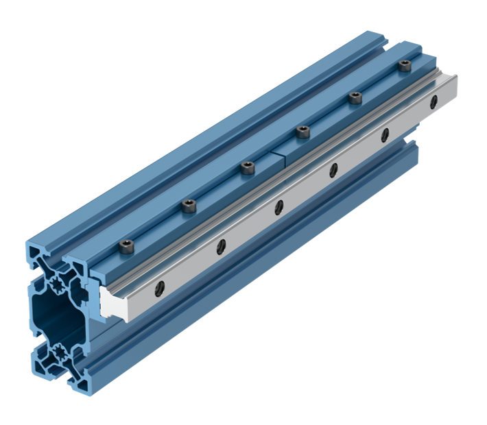
8. Once all sections have been installed, starting from one end of the rail and moving to the other tighten the rail and binder plate bolts to 10-11Nm. Ensure to tighten the rail bolt and the binder plate bolt together then move on to the next set.
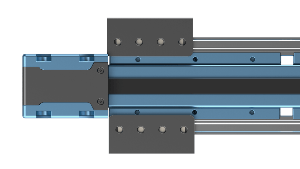
Butt-Joints
For linear guide systems over 3.33m it is possible to butt-join multiple rails together. It should be noted that butt-joints should be avoided if possible as they reduce the life expectancy of the bearing system.
This section has instructions that override those given in the general section for rail mounts. Follow these guidelines to successfully install a butt-jointed rail system.
An important consideration when planning your butt-jointed rail system is where the joints are located. Much like brickwork, it is important that rail joints do not align with each other or with extrusion joints. All joints should be offset to have optimal alignment and rigidity of the guiding system.

1. When butt-joining rails, it is important to pay attention to the engraving on the front face of the rail. The engraved text should be readable when the reference face of the rail support is on the bottom of the rail. All rails must have the same orientation relative to each other.

2. At the end of the first rail the rail support must half overlap with the next rail such that rail 1 and rail 2 each have two bolts passing through the same mount (shown in photo below).
3. All mounts on rail 1 should be tight except the mount that it shares with rail 2.
4. Slide rail 2 until it is contacting the end of rail 1.
5. Continue to apply pressure the rail so that the ends of the two rails are forced together and lightly tighten all of the rail and binder plate bolts at the joint to 1-2Nm.
6. Tighten the rail and binder bolts to 10-11Nm, starting from the side rail 1 is on.
7. After the rail support at the joint is attached, lightly tighten all of the rail and binder plate bolts on rail 2 (1-2Nm).
8. Double check the quality of the joint between rail 1 and rail 2. The transition between rails should be nearly imperceptible on the bearing races. With a dial indicator mounted on a bearing, change from rail 1 to rail 2 should be less than 0.02mm (0.0008”).
9. Continue the above steps at each joint.

Shimming
For linear guide systems that traverse multiple extrusions or the large 247.5mm extrusion, it is possible that width variations between the sections will necessitate shimming of the guide rail system. This can be done by purchasing the 20mm Profile Guide Rail Shim Kit If you are in such a scenario, follow these instructions:
1. Using a digital caliper, measure the width of your extrusions and determine which extrusion with the widest, or if using a 247.5mm extrusion determine its widest point.
2. Always begin installation of your guide rails on the widest extrusion and follow the general instructions given in the sections above.
3. Once transitioning to a narrower extrusion or encountering a taper in a XL extrusion, it is important to compensate for the difference in width by using shims.
4. Shims can be placed between the rail and the rail mount to compensate for the width change of the extrusion.
5. Measure the change in width between the two extrusions and use shims equal to that difference to space out the rails so that the overall width between rails remains constant.
6. Continue the process and when complete measure multiple locations along the bearing system to ensure that rail width does not deviate by more than 0.05mm.
Note: For larger gantry system where guides are mounted on separate extrusions, refer to the Vention Linear Axis Alignment Procedure technical document for instructions on how to align the frame to satisfy the product requirements.
![]()
Mounting Bearings on Rails
When mounting a bearing on the rail system caution must be used! Follow these instructions to install your bearing block:
1. Make sure the plastic insert in the bearing is still present. This prevents the ball bearings or ball chain from getting damaged during installation.
2. Place the plastic insert up against the end of the rail and align the bearing’s inner profile with the rail’s profile.
3. Carefully push the bearing onto the rail. It is important to keep the inset and bearing well aligned during this step. Significant force may be needed as the stiff bearing seals are pushed onto the rail.
4. Once the bearing is mounted on the rail, cycle it back and forth to ensure movement is smooth.
Once all of the above steps have been completed, you can attach your bearing to their corresponding gantry system. Check that everything moves smoothly when actuated by hand and there are no bumps or jolts in the system, especially if you have butt-joined rails.
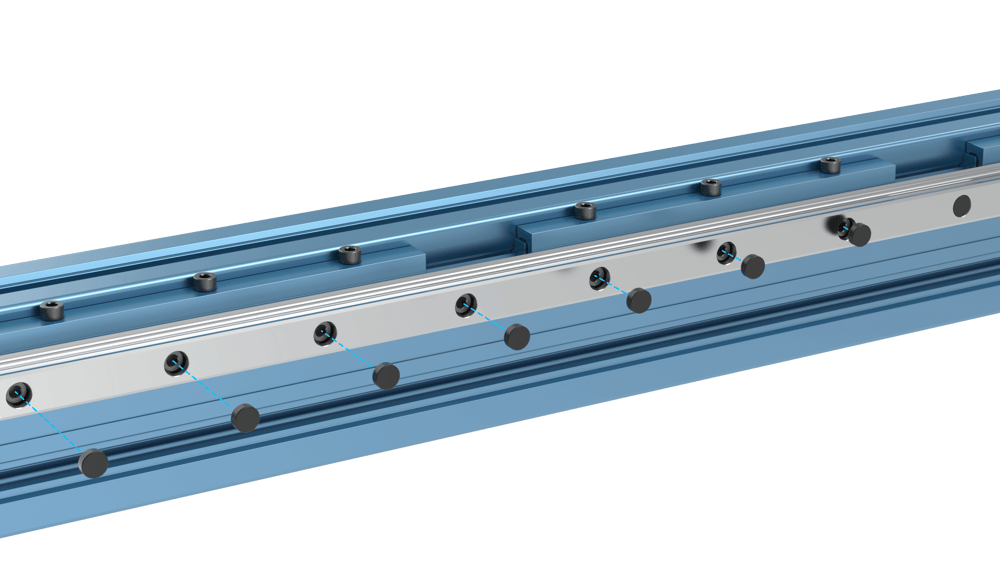
After verifying that the system is properly installed, alignment is correct, and the bearings all run smoothly, you can install the plastic plugs to cap off the rail mounting bolts. This helps to keep the system clean by preventing dust and debris from getting trapped in crevices. Installation can be done with a soft blow plastic mallet.
Important note: Lubricate the bearing using grease imediately after installation to avoid corrosion of the bearings and rails. See our Maintenance Technical Document for instructions on how to complete this.
Maintenance
For maintenance instructions, please see the appropriate section in our Maintenance Technical Document.
The zerk fittings that come in the bearing box are optional. Either the zerk fitting or an open grease port can be serviced using the Vention Grease Gun.