Datasheet
Updated: Tuesday, February 13th 2024
Latching Pushbutton Module Datasheet
Contents
Overview
The Pushbutton Module, CE-MD-004-0000, extends MachineMotion 2’s functionality with two latching (alternate action) pushbuttons. This plug-and-play module only requires a single connection to the MachineMotion 2 controller. Compatible modules, such as the Power Switch (CE-MD-005-0000) & additional Pushbutton modules can also be daisy chained to each other, making it possible to connect up to eight modules per MachineMotion 2 controller.
Features
- Includes two latching pushbuttons
- Connects (daisy chain) with compatible modules
- Configurable address
- Plug-and-play access from the Control Center, MachineLogic, and Python API
Programming Options
Program the Pushbutton Module using [MachineLogic] or the [Python API]. It can also be accessed from the Control Center.
Technical Specifications
General Specifications
| Part Number | CE-MD-004-0001 |
| Certifications |
|
| Weight | 0.45 kg |
| Dimensions | 46 x 88 x 133.0 mm |
| Material |
|
| Operating Temperature | 0 to 40°C |
| Included in the Box |
|
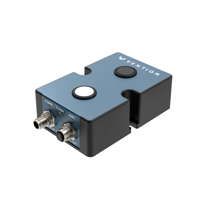
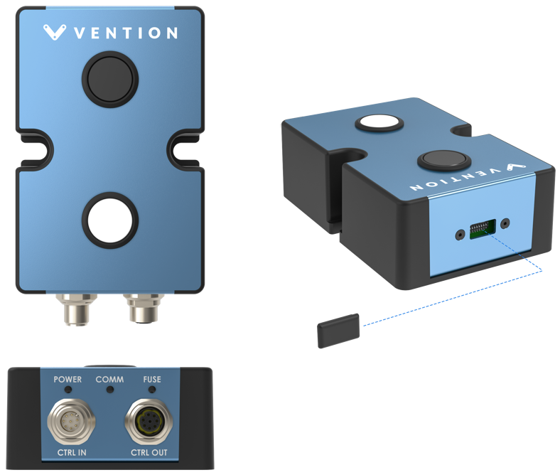
Latching Pushbutton Module Physical Interface
Pushbuttons (black/white)
| Pushbutton type | Latching (alternate action) |
| Mechanical life (minimum) | 250,000 operations |
CTRL IN Male M12 connector pinout
| Pin | Description |
|---|---|
| Pin 1 | 24 VDC (input) |
| Pin 2 | Ground (input) |
| Pin 3 | RS-485 A (input) |
| Pin 4 | NRS-485 B (input) |
| Pin 5 | Reserved |
| Pin 6 | Reserved |
| Pin 7 | N/A |
| Pin 8 | Reserved |
CTRL OUT Female M12 connector pinout
| Pin | Description |
|---|---|
| Pin 1 | 24 VDC (output) |
| Pin 2 | Ground (output) |
| Pin 3 | RS-485 A (output) |
| Pin 4 | NRS-485 B (output) |
| Pin 5 | Reserved |
| Pin 6 | Reserved |
| Pin 7 | N/A |
| Pin 8 | Reserved |
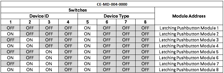
Latching Pushbutton module address configurations
Below are the valid address configurations that can be used for the Pushbutton module
Valid address configurations