

How to guide
Updated: Friday, April 26th 2024
Robot Programming in MachineLogic
Contents

Introduction
This guide covers how to program your collaborative robot using Vention’s Robot Programming in MachineLogic, both in the cloud on MachineBuilder (Vention’s CAD platform), and in reality on MachineMotion (Vention’s plug-and-play automation ecosystem). MachineLogic is a code-free programming, simulation and deployment tool dedicated to the creation of applications for MachineMotion. Combining robots with MachineLogic, you can automate your entire robot cell with ease.
MachineLogic comprises three steps:
STEP 1: Configure (configuration of automation components) STEP 2: Create an Application (code-free programming), and STEP 3: Operate (build an operator interface) Compatible with MachineMotion v2 only.
This guide primarily focuses on programming your robot in STEP 2, as well as the different robot states and errors you may encounter in reality. After reading this guide, you will be ready to program and/or simulate your robot-enabled application inside MachineBuilder, as well as in reality.
1 - Step 1: Configure
1.1 - In MachineBuilder
In order to simulate your robot using MachineLogic, your design requires a supported robot, as well as a MachineMotion v2, to be placed in the 3D scene. The following list all robots that currently, or that will soon support Robot Programming in MachineLogic in MachineBuilder:
- UR3e
- UR5e
- UR10e
- UR16e
- UR20
- FANUC CRX-10iA
- FANUC CRX-10iA/L
- Doosan H2017
- Doosan H2515
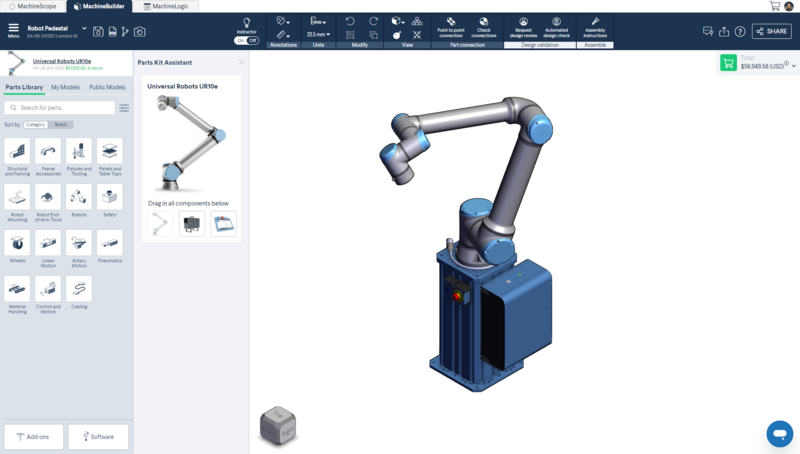
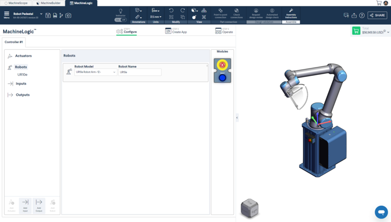
Click the MachineLogic tab to begin configuring the automated equipment.
- Click “Add Robot” to add your robot configuration.
- In the “Robot Model” dropdown menu, select the robot you would like to configure from your design.
- Once a robot model selected, it takes a few moments to initialize. Once ready, the “Robot Name” field will appear.
1.2 - On MachineMotion
At this time, Robot Programming for MachineLogic only supports Universal Robots e-Series cobots when programming in reality on MachineMotion. Read the Setup Guide to connect your UR e-Series robot to your MachineMotion.
2 - Step 2: Create an Application
To learn more about the basics of MachineLogic’s code-free programming before getting started, read the how-to guide How to configure, program and simulate with MachineLogic.
The sections below outline all robot functionality available for you to program your next robot-enabled application.
2.1 - Basic functions
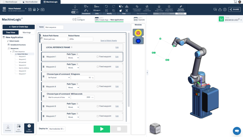
To use basic functions such as moving your robot and controlling your robot, you have the option to create local (useful for one-time use) robot paths in your main/child sequences.
Local robot path:
- Go to your main or child sequence.
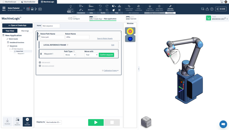
- Click on “Add command” > “Add robot path”.
- To add a waypoint, select “Add waypoints”
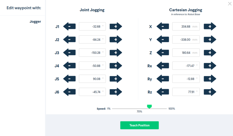
- When adding a waypoint in MachineBuilder, you can manipulate the robot using the Triad, Point to Point, or the Jogger.
- When adding a waypoint in the Control Centre on MachineMotion, you can manipulate the robot with the Jogger.
- Waypoints have the following attributes:
-
Path Type:
- MoveJ: Allows you to move your robot in an unrestricted way from the previous waypoint to the current waypoint.
- MoveL: Allows you to move your robot’s end of arm tool in a linear trajectory from the previous waypoint to the current waypoint.
- Fixed waypoint: Allows you to fix a waypoint based on the robot’s joint angles, regardless of reference frame.
-
Reference frame: depending on if you create a local or global path
- Local reference frame: Allows you to define where you want to place your reference frame or where you want to place your waypoints with respect to.
- Global reference frame: Allows you to specify the coordinate system from which the defined waypoints will be created with respect to. The reference frame is defaulted to the robot base otherwise.
-
Path Type:
- When adding a waypoint in MachineBuilder, you can manipulate the robot using the Triad, Point to Point, or the Jogger.
- To add a robot command, select “Add robot command”
- Set Payload: Allows you to set the weigth of the payload the robot will be manipulating, including the weight of your End-of-arm tool.
- Set Speed: Allows you to set the MoveL and MoveJ speed of your robot. All waypoint following this command will move to the prescibed speed. Speed and Acceleration follow a 1:1 ratio, meaning that a set speed of 200 mm/s will have an acceleration of 200 mm/s2.
- Wait for amount of time: Allows you to set an amount of time in milliseconds the robot will wait at a specific waypoint.
2.2 - Advanced functions
Most of our advanced functions are stored under Robot Assets. These assets are specifically meant to be used with the robot you would like to program and these assets could be used on a global level to execute in any sequence.
Note: Robot Assets are only available for programming in MachineBuilder. You must push your program to your controller to access the advanced functionality on your MachineMotion.
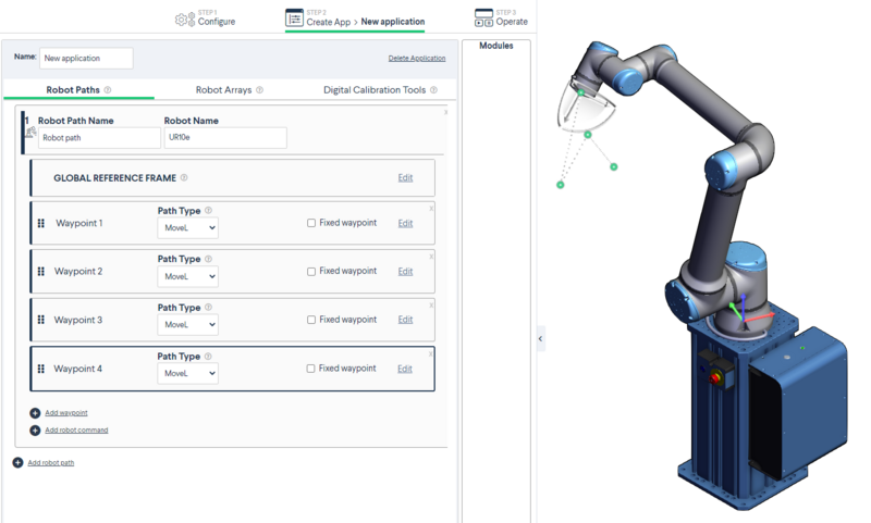
2.2.1 - Robot Paths
Robot paths allow you to create a series of robot waypoints and actions. Robot paths created at the robot assets level can be reused in the main or child sequences of your program.
- Click on “Robot Assets” > “Robot Paths”
- Click “Add robot path”
- Add waypoints, robot commands in your robot path
- Execute this robot path in the child/main sequence by clicking “Add Robot path”.
- In the drop-down menu, select the robot path you want to execute.
- Optional: Select a new global reference frame (otherwise, the global reference frame will be used)
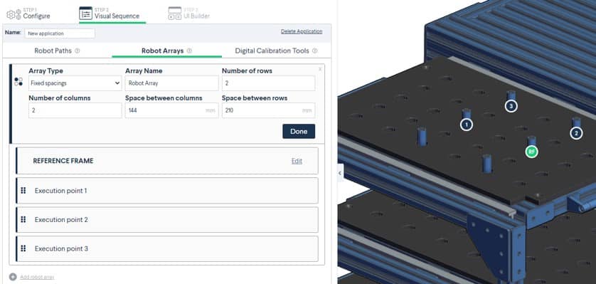
2.2.2 - Robot arrays
Robot arrays allow you to create a grid of execution points (which could also be referred to as reference frames), where the robot could execute a single “robot path” over each execution point. This robot array is meant to be used with the “Add Robot loop” command.
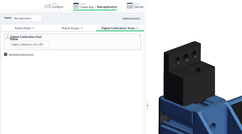
2.2.3 - Digital calibration tools
After you have completed your program, the last step before downloading your robot program is to add your calibration tool to your 3D design to accurately deploy your robot program from the cloud environment of MachineBuilder to your factory floor.
Add a digital calibration tool into your design to create a local coordinate system near an object for which a high-precision pick and place movement is required. The robot will then update all waypoints programmed to move with respect to this local coordinate system. For best results, place the digital calibration tool using the following steps:
- Make sure that the placement of the digital calibration tool in MachineBuilder is at a repeatable position you can locate on your robot setup in real-life
- Make sure that the digital calibration tool is directly connected to the part which the robot path is programmed with
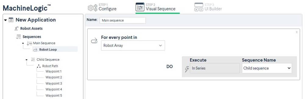
2.2.4 - Robot Loops
This command allows you to utilize a combination of robot arrays and robot paths.
- Robot Paths: A set of waypoints and robot commands.
-
Robot Arrays: Robot arrays allow you to create a grid of execution points (which could also be referred to as reference frames), where the robot could execute a single “Robot Path” over each execution point. To create a robot array, use:
- Fixed spacings array: Creates a 2D pattern that has equal spacing between rows and columns. Select the reference point where you would like the array to be located, fill in the fields and click “Generate”.
2.3 - Other Robot Functionality
2.3.1 - End-of-arm tool commands
End-of-arm tools can be controlled by Vention’s IO module and the Output command in MachineLogic.
3 - Robot Functionality on MachineMotion
Over the course of the robot’s physical programming and operation, you may encounter certain robot states and errors. The sections below outlines those states, as well as how to troubleshoot them in the event of an error occurring. The sections will also cover best practices for programming your robot with MachineLogic.
Notes:
- Robot Programming in MachineLogic is currently not compatible with Multi-Controller systems.
- Pausing a running robot program will not pause the Robot Motion, but rather pause the robot path command. Be careful when pausing and immediately approaching your robot cell.
3.1 - Robot States
The table below outlines the various states the robot may find itself in, how it may have gotten into that state, and how to get out of it and return to normal operation.
| State | Description | Screenshot |
|---|---|---|
| Operational | System and robot are in operational state. No problem or errors have been detected. Ready for operation. |  |
| Non Operational | Occurs after a reset or fault clearing event, usually brought on by an Emergency Stop or Fault state, and trying to move the robot or play a program. To return to a Ready state, select Enable Robot. |  |
| Emergency Stop | Occurs when a physical emergency stop button is pressed. Your MachineLogic program is stopped. To return to normal operation, release all physical (and software) emergency stop buttons and select RESET. If the reset procedure succeeds, your robot is now in a Not Ready state. |  |
| Protective Stop | Occurs when the robot collides with an external object or person. Your MachineLogic program is stopped. In this state, the robot is back-drivable. Move the robot away from any possible collision and select Enable Robot. The robot should now be in a Ready state Note: An incorrectly set or overweight payload may trigger a Protective Stop. To re-enable the robot without retriggering the fault, manually support (lightly push up) at the robot’s flange before enabling. |
|
| Reduced Mode | Occurs when a safety device wired into the reduced pin on the robot controller is triggered (ex: walking into an area guarded by an area scanner). Your MachineLogic program continues, but at a slower speed. It returns to full speed once the triggering fault is cleared. | 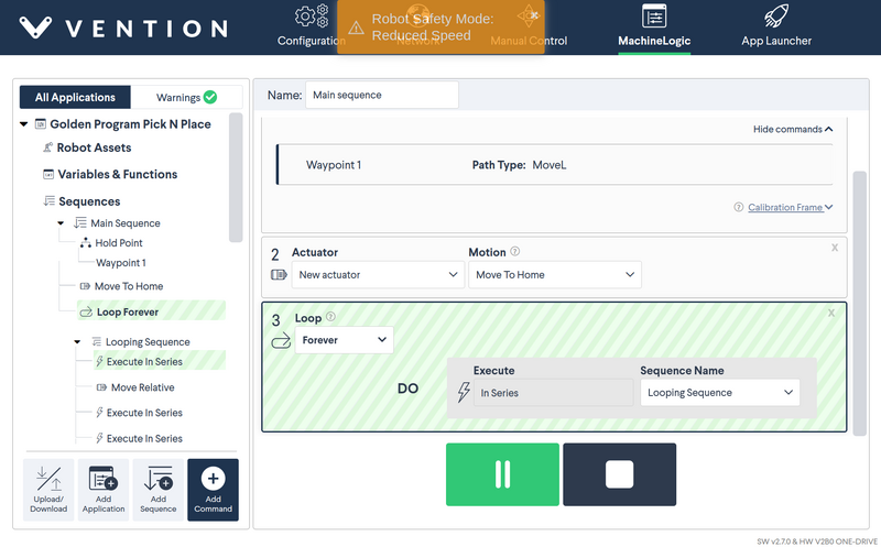 |
| Fault | Occurs when a variation of errors not captured by the safety and operational state machine arise. Your MachineLogic program is stopped. To return to normal operation, the fault must be cleared on the robot’s native pendant before continuing. Once the fault is cleared, the robot is in a Not Ready state. |  |
Note: MachineMotion does not support Safeguard Stop. Consequently, any Safeguard Stop event triggers an Emergency Stop, and that flow must be used to return to normal.
3.1.1 Re-Enable from Robot Pendant
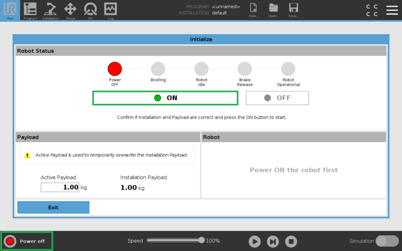
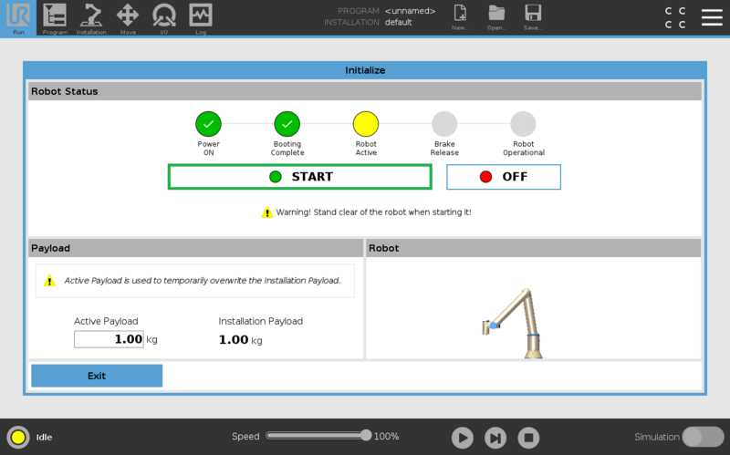
In certain cases (ex: heavy safety breach), the robot may required to be re-enabled from the robot controller’s pendant. To get your robot back into an enabled state, simply select the State Indicator in the bottom left (see Figure 15a below). The robot may be completely powered down, start by powering it on (Figure 15a) and then enable it (Figure 15b). If the robot is already in an Idle state, enable it (Figure 15b).
3.2 - Motion Planner Errors
The table below highlights some of the most common errors you may encounter when trying to move your robot and plan its path.
| Error | Error Code | Error Category | Description and Tips |
|---|---|---|---|
PLANNING_FAILED |
-1 |
Overall Behaviour | This error usually occurs when certain robot movements exceed the limits set in the planner. Simply reduce the |
INVALID_MOTION_PLAN |
-2 |
Overall Behaviour | This error usually occurs when a robot path (generally linear - MoveL) will collide with the robot, trying to go through it to achieve the next waypoint. |
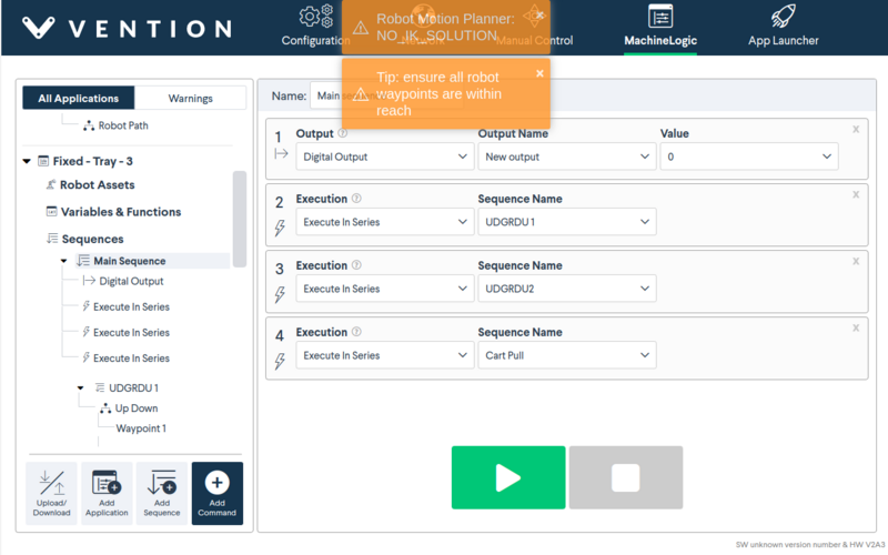
NO_IK_SOLUTION |
-31 |
Kinematics Errors | This error usually occurs when a waypoint is unatteinable in the current solution space. Try moving the waypoint closer, within reach of the robot. Verify that the waypoint is also possible with the current joint placement |
Motion planner errors, along with tips, will appear at the top of the Control Center.
The table below highlights less common errors and their respective category.
| Error | Error Code | Error Category |
|---|---|---|
MOTION_PLAN_INVALIDATED_BY_ENVIRONMENT_CHANGE |
-3 |
Overall Behaviour |
CONTROL_FAILED |
-4 |
Overall Behaviour |
UNABLE_TO_AQUIRE_SENSOR_DATA |
-5 |
Overall Behaviour |
TIMED_OUT |
-6 |
Overall Behaviour |
PREEMPTED |
-7 |
Overall Behaviour |
START_STATE_IN_COLLISION |
-10 |
Planning and Kinematics Request Errors |
START_STATE_VIOLATES_PATH_CONSTRAINTS |
-11 |
Planning and Kinematics Request Errors |
GOAL_IN_COLLISION |
-12 |
Planning and Kinematics Request Errors |
GOAL_VIOLATES_PATH_CONSTRAINTS |
-13 |
Planning and Kinematics Request Errors |
GOAL_CONSTRAINTS_VIOLATED |
-14 |
Planning and Kinematics Request Errors |
INVALID_GROUP_NAME |
-15 |
Planning and Kinematics Request Errors |
INVALID_GOAL_CONSTRAINTS |
-16 |
Planning and Kinematics Request Errors |
INVALID_ROBOT_STATE |
-17 |
Planning and Kinematics Request Errors |
INVALID_LINK_NAME |
-18 |
Planning and Kinematics Request Errors |
INVALID_OBJECT_NAME |
-19 |
Planning and Kinematics Request Errors |
FRAME_TRANSFORM_FAILURE |
-21 |
System Errors |
COLLISION_CHECKING_UNAVAILABLE |
-22 |
System Errors |
ROBOT_STATE_STALE |
-23 |
System Errors |
SENSOR_INFO_STALE |
-24 |
System Errors |
3.3 - Best Practices
When programming your robot, either in MachineBuilder, or on your MachineMotion, there are a few best practices to follow to make sure you’re successful right out of the box.
- Homing/Sequence Start : It is recommended that you move your robot to a position that is similar to your first waypoint in order to avoid any singularities or joint limit errors.
- MoveL vs MoveJ : As specified above, MoveL specifies that the robot will move along the linear path defined by 2 waypoints. In some cases, the linear path crosses directly through the robot, creating a possible collision with itself. It is recommended to use MoveJ in these instances. It is also recommended to use MoveL whenever a motion requires precision, and MoveJ when moving between precise tasks.