Designing Machine Tending Equipment
What is Machine Tending?
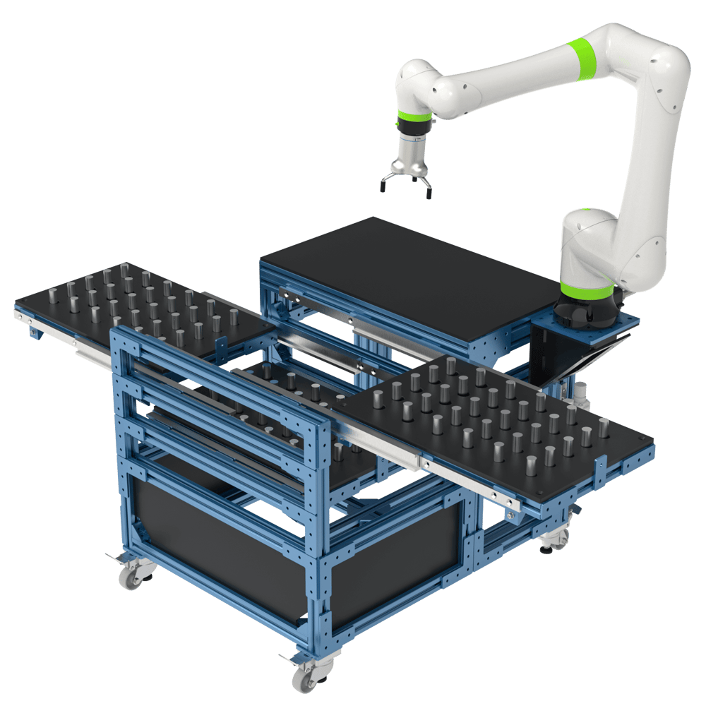
Machine tending allows operators to continuously run production machines with minimal human input. Typically, a large number of parts are stored in a part presenter, angled tray, or drawer system, which the robot loads and unloads parts from. Learn more about machine tending applications here.
Part Presenting
Once you select a gripper with the appropriate finger design, the next step is to customize your part presenter. This is the structure that will hold the parts to be tended (pre- and post-machining). The two most common part presenter options are the configurable trays and the drawers.
Configurable Trays
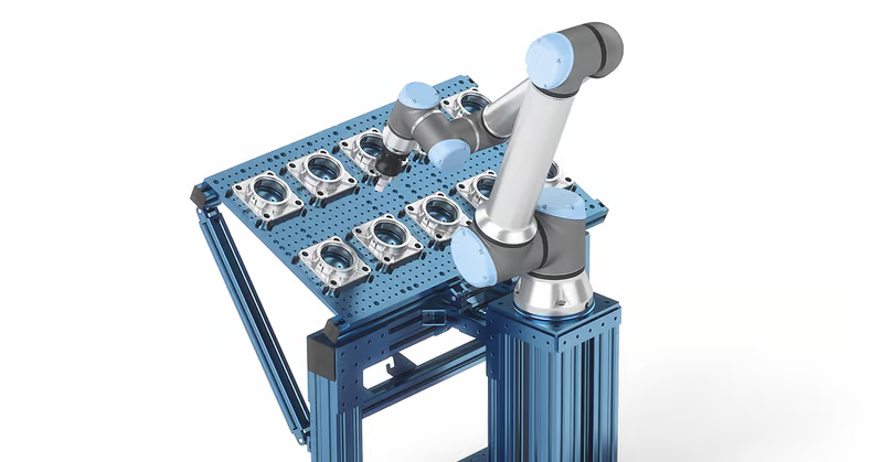
Configurable trays consist of a base plate to which pins or plates can be attached, such as threaded nylon pins or steel rest buttons, that act as datum locators. With nylon pins, the work surface can be configured to create repeatable locators specific to the part being tended. Part density on the base plate is easily adjusted by reconfiguring the pins. Trays are typically simple and inexpensive to deploy but offer limited autonomy in terms of part-holding capacity.
Depending on part dimensions, operators may typically load anywhere from 16 to 32 parts per base plate. To optimize your tray, consider your fingers’ design and size to determine the area they cover while the gripper is in the “open” position. The fingers are typically the main limitation in terms of number of parts to have on a tray since they can easily collide with other parts at the pick-up and drop-off stages. When designing the tray it is advised to add clearance to the part picking locations. The amount of clearance will depend greatly on the style of gripper used, as well as any application specific requirements.
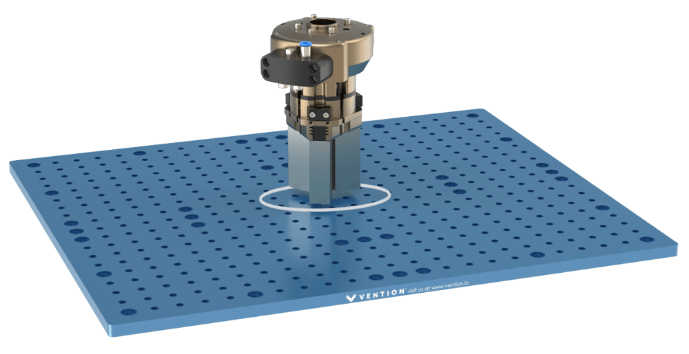
To assist in the repeatability of the picking, a self-centering gripper can be used to account for any offset within the picking area.
Drawer System
Drawer systems typically involve 3 to 5 drawers, each holding up to 50 parts depending on drawer and part size. Drawer systems have a high part-holding capacity, and can range from 100 to 250 parts total. The main considerations should all be examined while designing drawer systems:
- Robot reach
- Precision requirements
- Locking system
- Opening / closing process
Precision Telescopic Slides
The telescopic slides are critical in machine tending applications as they provide a smooth and accurate drawer for the robot to use. Regular drawer slides are in-capable of meeting the high number of duty cycles and precision requirements for this application. Therefore Vention offers high capacity, high precision telescopic slides. These slides are machined from steel and use ball bearings in V-grooves for high rigidity.
See the precision telescopic slides document for more information on assembly and alignment of the slides.
Machine Design
Proper machine design for machine tending applications is crucial to ensure efficient and reliable operation. The following sections will explore design guidelines which apply to most standard machine tending applications. If additional guidance is needed, please contact our Application Engineering department.
Structural Design
When designing the machine tending structure, it is critical to ensure that the design is rigid when the drawer hardware is not yet installed. In other words, the drawers should never be relied upon as a structural support.
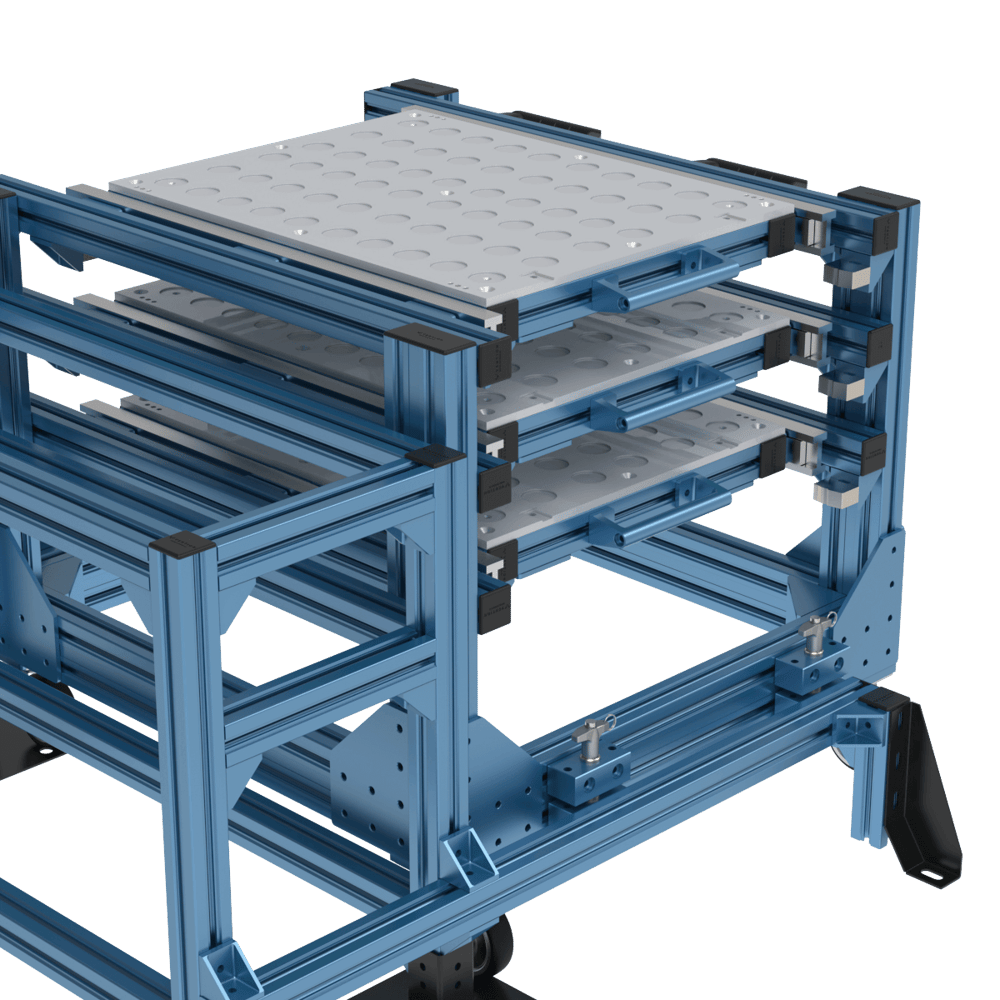
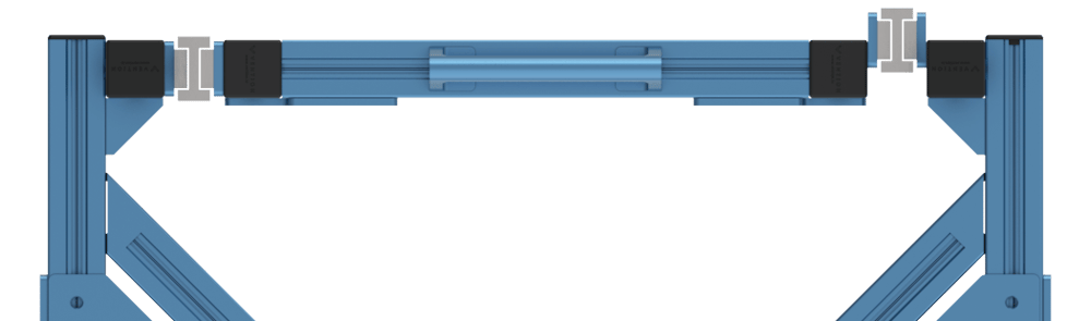
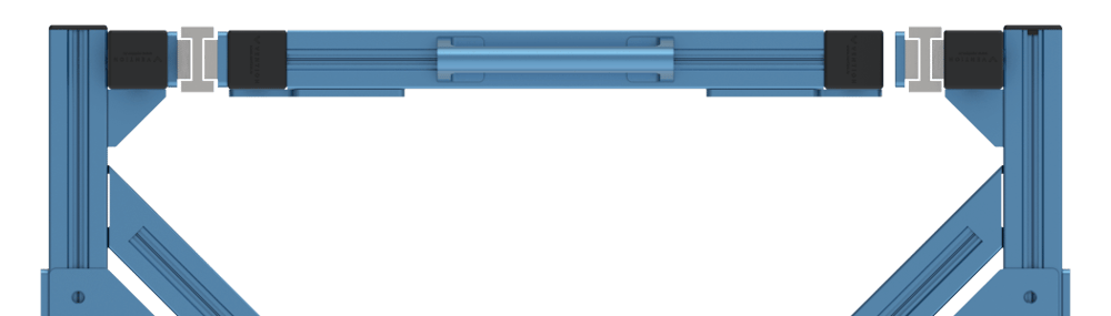
To increase the overall rigidity of the frame, 45mm x 90mm extrusions can be used as vertical supports. Angular bracing with 45 degree inline connectors can be used to reinforce the joint. A combination of these techniques can be seen in the photo below.
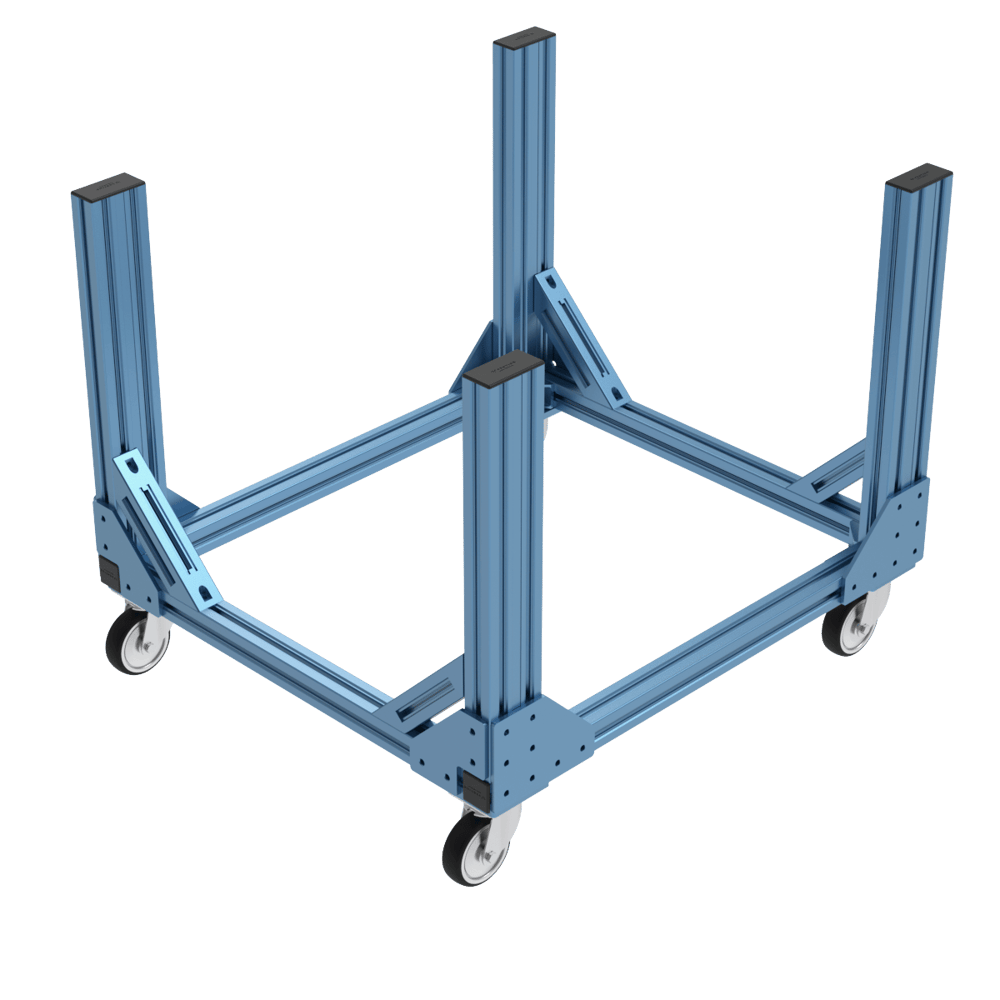
Optional Wheels
If the specific application requires a moving cart and a docking station, wheels can be added the structure to make a machine tending cart. Due to the repeated movement of these carts, swivel caster wheels such as MO-WL-001-0005 will perform well for most applications. Though the calibration procedure should account for misalignment of the working area, it may be beneficial to incorporate leveling casters such as MO-WL-003-0001.
Tray Design
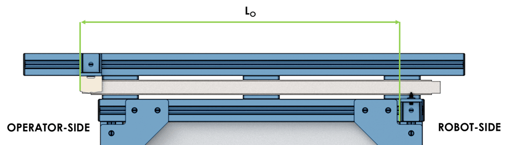
Proper tray design is critical to the success of machine tending applications. If not respected, it is possible for drawers to overlap into the robot’s picking area and to prevent proper function of the application.
To ensure that this is not an issue, the length of the tray can be at most a third of the total stroke of the drawer, equal to both Lr and Lo detailed below. This will ensure that there is no overlap between the operator-side, neutral, and robot-side positions.

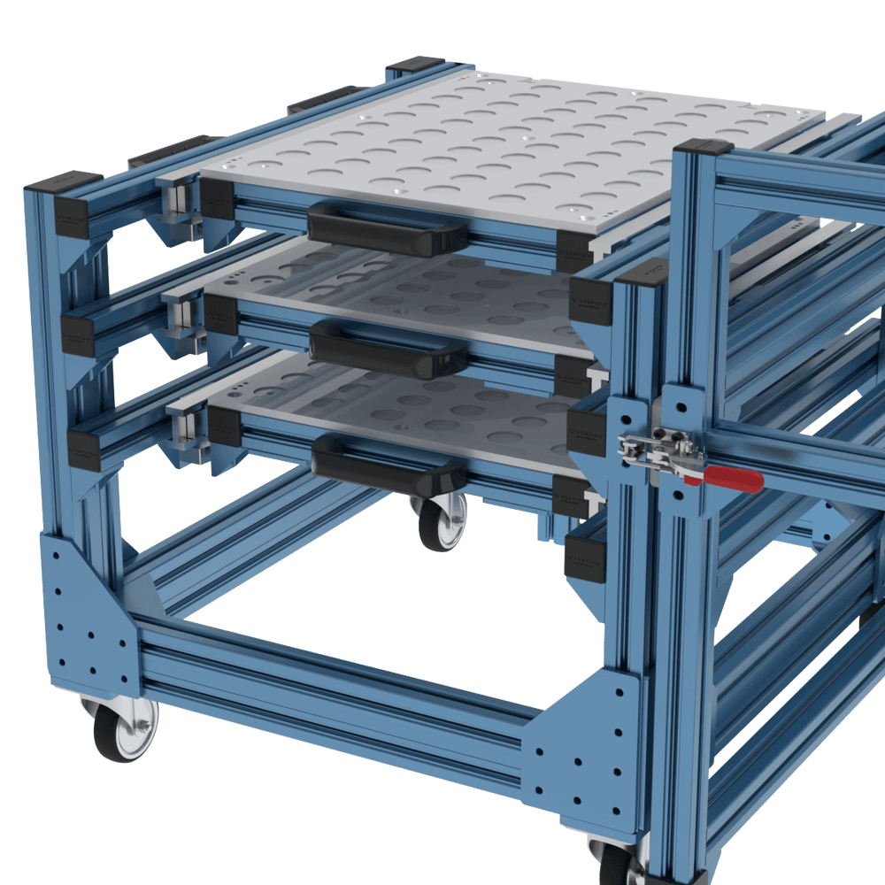
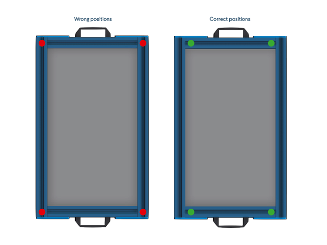
We recommend installing panels on top of the drawer as the installation process is simpler than panels that are inside or below the extrusions. We also recommend adding countersink holes and locating them on top of the extrusions that are perpendicular to the slides of the drawers (see image below) since pressure points should be avoided on sliding mechanisms.
Calibration Tool Integration
When designing drawers for machine tending applications, it is critical to consider the precision requirements and the calibration method used in the design. The requirements for this will vary greatly depending on the precision needed in the system.
To ensure precise calibration of the array of parts on the tray, it is imperative to tolerance the placement of the array with respect to the calibration points. The precision of the tolerance will vary based on the application-specific requirements as well as the type of gripper being used (a self-centering gripper is more lenient where as a 2-finger gripper will need a higher degree of positional accuracy).
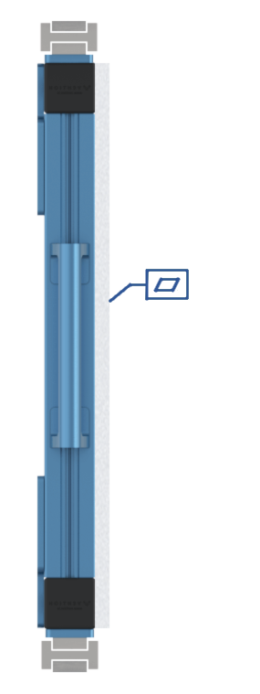
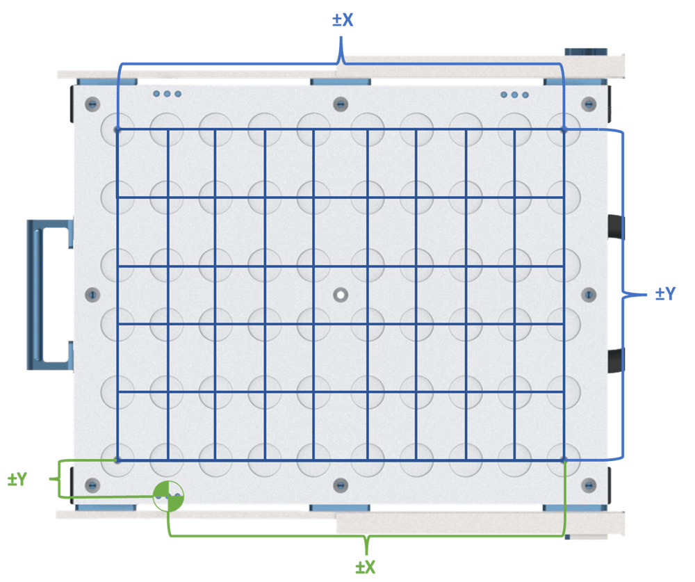
A general guideline is shown below, where the array of parts on the tray (blue) and the drawer origin (green). The drawer origin, obtained through calibration, should maintain the same tolerances between any of the points on the array. If not, points further away may not be grippable. Additionally, the flatness of your tray (shown on the left) must be within the predetermined tolerance limits. Consult our application engineering department for more insight on the tolerancing and design of your machine tending trays.
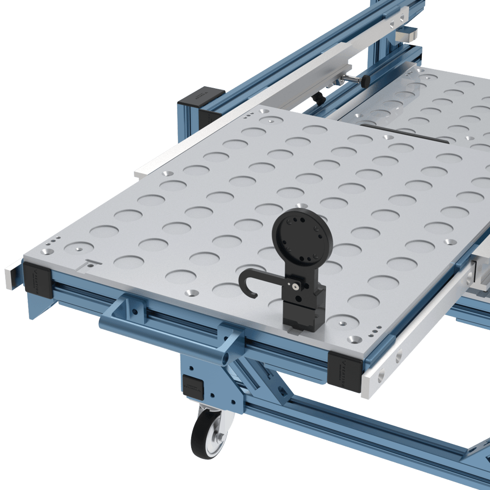
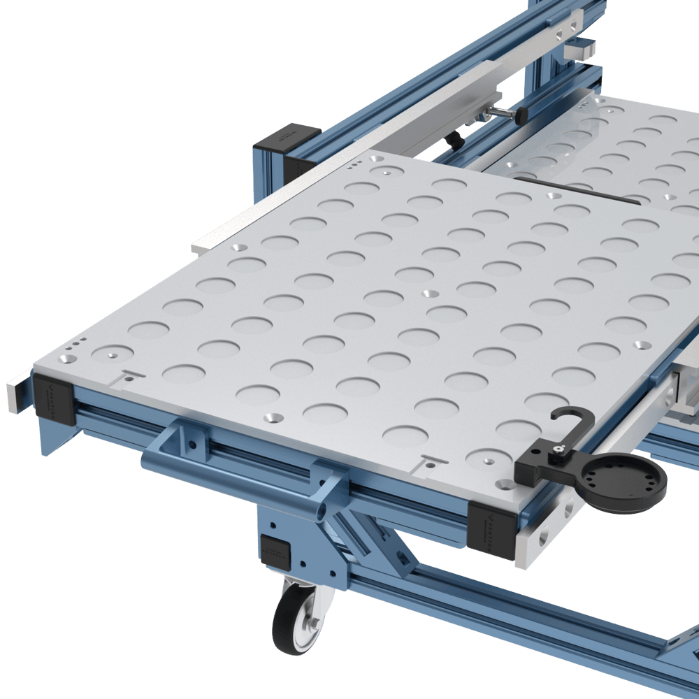
Different calibration techniques can be used for any given application based on the precision required, such as 3-point calibration, which will simply change the pattern or features that are used to calibrate. Below are two examples of potential ways of calibrating on a tray. Other 3-point calibration methods can be used to obtain the required precision of the application but may require custom componentry.
Vention offers a calibration interface block, a calibration flange, and a drawer opening calibration flange for machine tending.
Note: Frequency of calibration will vary from application to application, re-running the calibration procedure periodically is recommended to ensure no long-term loss of accuracy.
Note: When using the machine tending calibration flange, the choice of handle is very impactful. Please design your robot-side handles using round extrusions and the round extrusion handle bracket.
Telescopic Slide Design Considerations
To ease alignment of slides after assembly, the design needs to allow for certain parts to float before being tightened in place. Slides need to be parallel, coplanar, and correctly spaced. Each of these requirements applies to the frame side as well as the drawer side.
In general, a design should allow the adjustment of the following issues:
- Height of the slide relative to the frame.
- Width of the drawer.
- Rotation of the slide relative to the frame.
- Rotation of the slide relative to the drawer.
Each of the issues above will happen during assembly due to differences in extrusion profiles, tolerances on extrusion cuts and assembly. Any of these issues can cause binding, variable drawer opening force and lower drawer life. ~~~~
The type of connector used in each joint on a machine tending cart should be carefully considered. Any joint that is used to align the slides should utilize General-precision (GP) connectors. The reason is that these joints have an inherent amount of looseness allowing the assembler to tighten the joint in the correct location.
Drawer Design
Indexer and Locators
There are three positions that can be achieved with a machine tending drawer system, robot-side, closed, and operator-side. While the robot tends the parts with a drawer open on the robot-side, an operator can open a drawer on the operator-side to remove machined parts and refill with raw parts. Drawer systems can be manual or automated, and locking mechanisms allow for high repeatability.
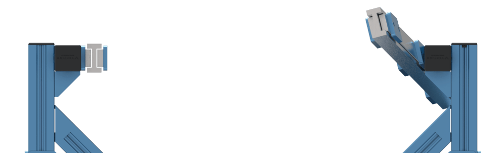
For manual systems, the robot arm simply pushes or pulls the drawers in and out as needed. An indexer system using plungers and catches is needed to ensure the positioning is accurate. To reduce the inertial load on the cobot during the drawer opening and closing process and ensure accurate positioning, the Machine Tending Indexer Catch along with an Indexer Spring Plunger can be used. When spacing these indexers, they should be located as shown:
When designing and assembling a cobot drawer system, ensure that smoother sides of the indexer catches are both facing towards the inside of the drawer. This will ensure that the cobot will have to overcome a much lower force to open and close, while also guaranteeing that the start and end points are clear.
Once properly located along the travel of the precision telescopic slides, the depth and the pressure of the spring plungers should be adjusted. This can be done simply by following the instructions presented in the ‘Adjusting the Spring Plunger’ section of the following document.
Locking Mechanism
If a mobile cart is required, there are additional considerations when comparing to a stationary drawer system. When operators are moving machine tending carts, there is a chance of drawers releasing from their indexer catches and moving during transit. To avoid this issue, it is important to incorporate a locking mechanism when the cart is on the move.
After the operator has re-docked their machine tending cart to the robot frame, it is necessary to unlock the drawers, or there will be a program failure once the cobot attempts to open the drawers.
Additionally, when moving machine tending carts it is necessary to ensure the locks are in place properly, if not there is a risk of the drawers opening and the cart potentially tipping.
Drawer Assembly & Alignment Procedure
For detailed instructions on best practices for assembly and for adjustment see the precision telescopic slides technical document.
Robot Frame
Bracing
In order to have acceptable repeatability, the robot mounting plate must be attached to a rigid frame, such as the Vention Cobot Pedestal. This frame should be firmly anchored to the floor and be properly braced.
Cart to Frame Interface
To ensure calibration can be kept consistent after the cart has been removed from the robot frame, it is necessary to implement a locking mechanism. An example of this would be to have a quick-release pin and locating block paired with a toggle latch. These two points of contact should allow for sufficient rigidity that calibration can be completed only once at the beginning of deployment.
For ease of use, the quick-release pins can be placed vertically. This allows for the corresponding blocks to be easily aligned. The toggle latch can be installed horizontally near the operator-side to enable easy locking and unlocking once docked. Either a rest pad or an extrusion end cap can be used so as to not damage any interfacing extrusions with repeated use.