Designing with T-Slot Aluminum Extrusions
T-slot aluminum extrusions generally enable quick design and manufacturing of structural frames, but their design can have a huge effect on overall structural integrity. Below are our three top design tips for creating reliable, rigid, and industrial-grade t-slot aluminum extrusion structures.
1. Choosing the right extrusion profile
Not all extrusion profiles are created equal. Two profiles might have the same outer dimensions—45 x 45 mm, for example—but very different rigidity, depending on their area moment of inertia.
Another key aspect to consider is the cross-sectional area, which affects the overall weight of the assembly. Since the best profiles are highly rigid and lightweight, the best performance indicator is the area moment of inertia to surface area ratio. The table below lists some key parameters for five well-known extrusion models.
VENTION V2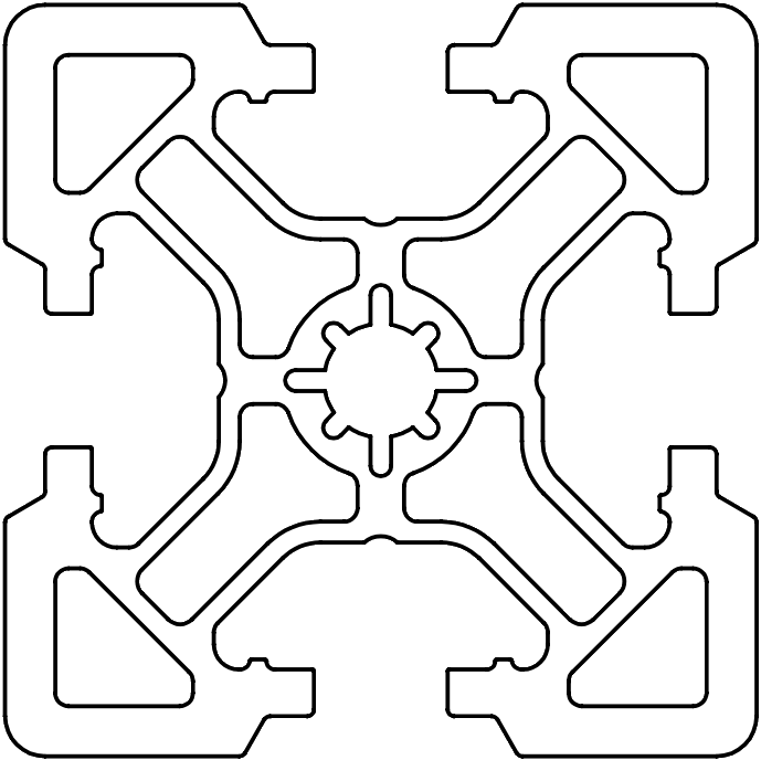 |
Extrusion A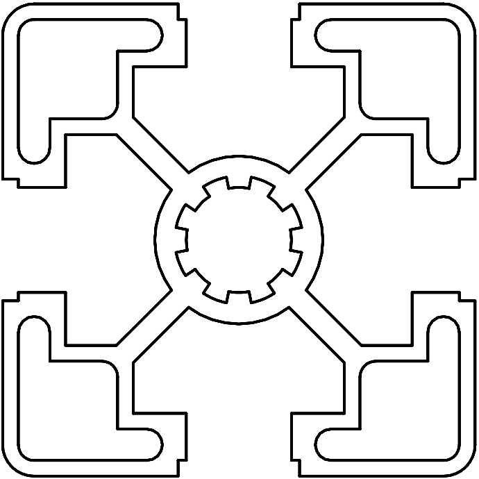 |
Extrusion B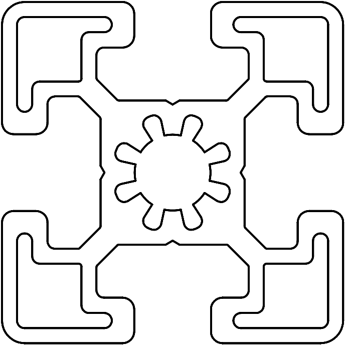 |
Extrusion C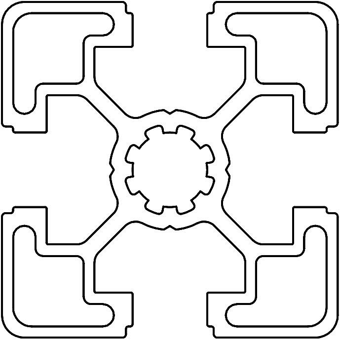 |
Extrusion D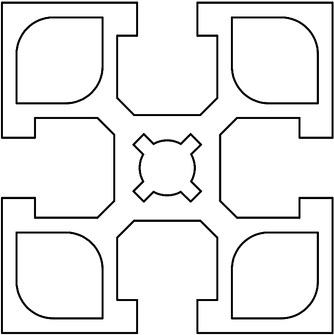 |
|
|---|---|---|---|---|---|
| Profile Dimensions (mm) | 45 x 45 | 45 x 45 | 45 x 45 | 45 x 45 | 45 x 45 |
| Material (aluminum) | 6005-T5 | 6560-T6 | 6105-T5 | 6063-T5 | 6063-T5 |
| Profile area (mm2) | 761 | 563 | 757 | 571 | 737 |
| Area moment of inertia (mm4) | 162,325 | 107,780 | 139,310 | 109,635 | 141,720 |
| Torsional constant (mm4) | 31,851 | 19,394 | 31,042 | 19,836 | 39,719 |
| Weight per meter (kg) | 2.06 | 1.63 | 2.05 | 1.55 | 2.03 |
| (Area moment of inertia) / (Surface Area)(mm2) | 213 | 191 | 184 | 192 | 192 |
| Max deflection (500mm cantilever) at 1500 N force (mm) | 5.58 | 8.28 | 6.50 | 8.25 | 6.30 |
| Stress (500mm cantilever) at 1500 N force (MPa) | 103.96 | 156.57 | 121.05 | 153.48 | 117.11 |
| Torsional displacement (1m length) at 50 Nm torque (degrees) | 3.46 | 5.68 | 3.55 | 5.55 | 2.77 |
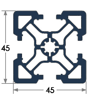
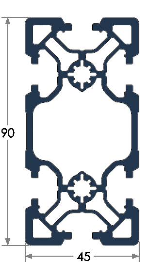
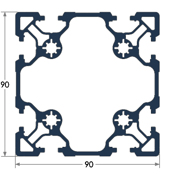
Vention currently offers six extrusion sizes. Our 45 mm series of extrusions suit many applications, from industrial furniture to robot range extenders. There are three sizes of extrusions using 45 mm increments—45 x 45 mm, 45 x 90 mm, 90 x 90 mm and 180 x 22.5 mm—all share the same mounting hardware.
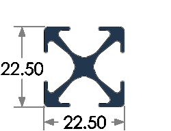
Our light-duty extrusion profile, 22.5 x 22.5 mm, is useful for applications with low loads and low weight limits. See the following table for a detailed breakdown of each profile’s properties.
| Part Number | Length range (mm) | Yield strength (MPa) | Area moment of inertia (mm^4) | Torsional constant (mm^4) | Weight per 45 mm | Fastener size | |
|---|---|---|---|---|---|---|---|
 |
ST-EXT-006-XXXX | 45–1,530 | 140 | 8,885 | 2,043 | 20.1 g | M8 x 1.25 |
 |
ST-EXT-101-XXXX | 45-2,295 | 240 | 103,180 | 29,000 | 63.87g | M8 x 1.25 |
 |
ST-EXT-001-XXXX | 45–2,295 | 240 | 162,325 | 31,851 | 92.5 g | M8 x 1.25 |
 |
ST-EXT-002-XXXX | 45–3,330 | 240 | 1,111,757 Ix 287,967 Iy*** | 189,708 | 149.4 g | M8 x 1.25 |
 |
ST-EXT-005-XXXX | 45–3,330 | 240 | 1,850,913 | 941,414 | 228.6 g | M8 x 1.25 |
 |
ST-EXT-009-XXXX | 45–1,530 | 240 | 77,150 Ix 3,783,293 Iy* | 52,788 | 162.9 g | M8 x 1.25 |
 |
ST-EXT-011-XXXX | 1845-3330 | 140 | 76,063,900 | 80,813,953 | 1085.2 g | M8 x 1.25 |
45 x 45 mm Light Duty Extrusion
The new 45 x 45 mm Light-duty (ST-EXT-101-XXXX) is Vention’s newest offering extrusion profile, allowing for an alternative 45 x 45 profile that is perfect for applications with lower loads and weight limits. With a profile area reduction, and in turn weight per 45mm length, of 31% the 45 x 45 Light-duty offers a best in class balance between the lightweight nature of the profile and the structural rigidity based on weight. 45 x 45 Light duty extrusions are identified with a Light Duty informative label.
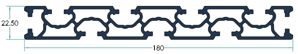
Tabletop Extrusion
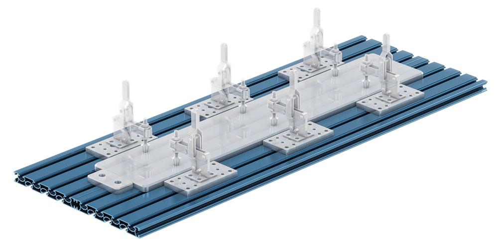
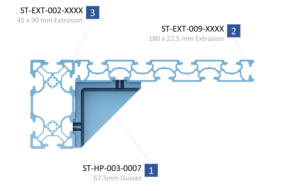
The 22.5 x 180 mm tabletop aluminum extrusion is perfect for workstation table tops, CNC worksurfaces, machine-tending workstations, and more. It provides a large mounting surface with evenly spaced t-slots, which are ideal for modular jigs and fixtures.
The tabletop extrusion t-nut profile, v-grooves, and spacing follow Vention standards, making it compatible with all gussets, assembly plates, and frame accessories.
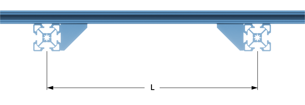
Although only 22.5 mm thick, this extrusion is still capable of supporting robots that produce 1800 Nm of e-stop torque (Yaskawa HC10 for instance). That is, as long as support extrusions are installed running perpendicular to the tabletop. For maximum strength, these joists should be placed a maximum of 315 mm apart (distance L) and attached firmly attached to the machine frame.
When simply supported a table top extrusion of 1530 mm length can support a load of 100 kg. For increased load capacity add supports at consistent intervals.
To mount the tabletop extrusion flush with 45 mm extrusions, use the 67.5 mm gusset (ST-HP-003-0007). In order to achieve the proper spacing, a 45 x 90 mm or 90 x 90 mm extrusion is required.
Tabletop extrusions have a total of nine t-slots, which allow many different mounting options.
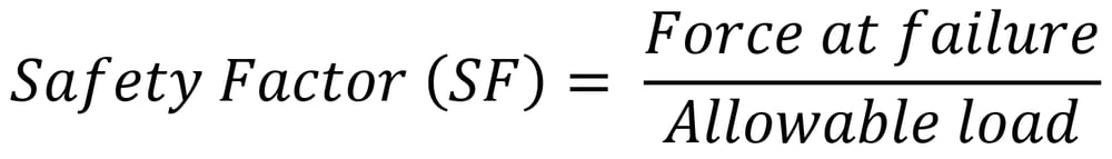
Calculate the safety factor
You must always add an adequate safety factor (SF) for your situation. For instance, if a structure will theoretically fail at 1000 N of force, a safety factor of two would establish an allowable load limit of 500 N. Safety factor is a measure of how confident you are of your calculations.
Safety factors should be based on (but not limited to) the following variables:
- Calculation accuracy and thoroughness.
- Environmental conditions.
- Consequences of failure.
- Cost of overbuilding.
⚠️ Important: Determine safety factors according to your industry’s standards. Always increase the safety factor if there is any risk of injury occurring due to system failure.
Calculate bending stresses
To evaluate whether a profile meets your design requirements, use free body diagrams and basic static calculations to estimate the applied load on the structure. Do the same for each individual extrusion.
Once determined, use the formulas below to calculate the maximum deflection and bending stress for each of your application-critical extrusions.
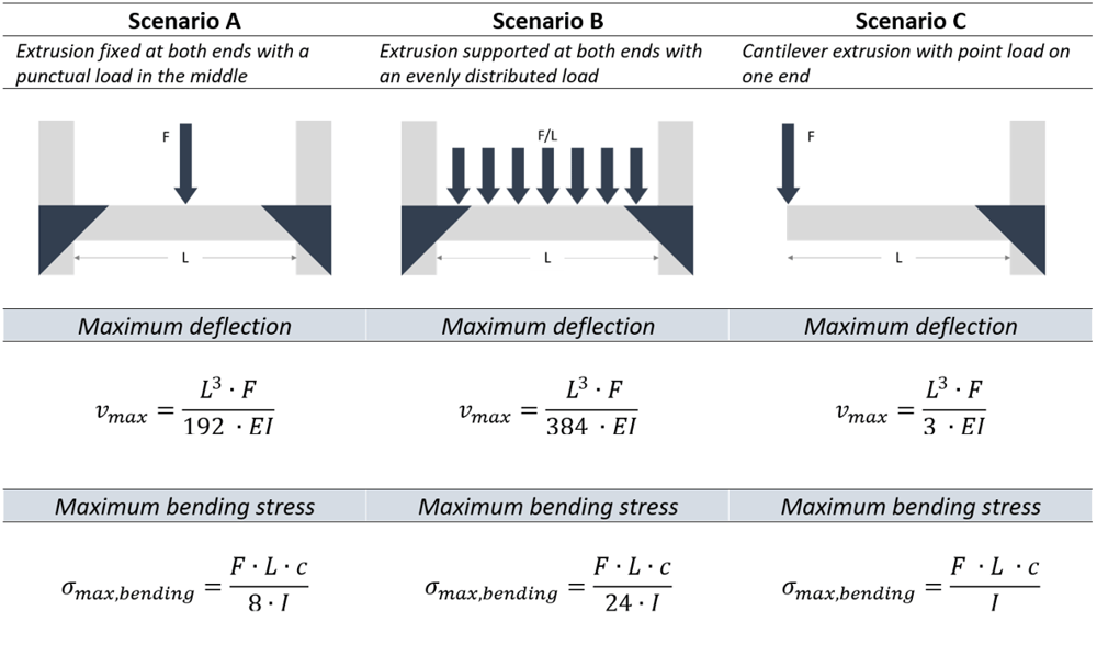
Where:
| Variable | Description | Value | Unit | Notes |
|---|---|---|---|---|
| Vmax | Maximum deflection | - | mm | |
| L | Extrusion length | - | mm | |
| F | Applied force | - | N | |
| E | Young modulus | 68,900 | N/mm^2 | Aluminum 6063-T5 |
| I | Area moment of inertia | see table | mm^4 | |
| σmax,bending | Maximum bending stress | - | N/mm^2 | |
| c | Distance from neutral axis | 22.5 | mm | Applicable for 45 x 45 mm profile |
Compare the max bending stress with the material’s yield strength to estimate your extrusion’s capacity to withstand the required load. For Vention’s V2 6005-T5 aluminum extrusions, for example, a calculated bending stress of 65 N/mm2 is well below the material’s 240 N/mm2 yield strength.
Remember, however, that this is only an estimate, since it does not account for other important factors like the extrusion’s own weight and shear stress.
Calculate buckling strength
When calculating the strength of a structure it is important to consider buckling. Buckling occurs when a long vertical beam is compressed by a force. The beam tends to bend outwards, which further reduces its structural integrity, leading to sudden failure. This failure is most likely to happen with vertical beams, because the load due to gravity is larger than the other forces acting on the structure.
Calculate the max allowable buckling load using Euler’s critical load formula. First, determine which end conditions match your scenario based on the joint types. Then use your chosen extrusion profile’s column length factor and area moment of inertia to calculate maximum load capacity.
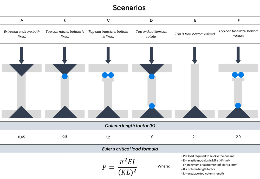
Third, compare the max load capacity to your expected force from a free body diagram, and determine the safety factor. Your safety factor should exceed standards for your industry.
2. Choose the right joint configuration
Selecting the right extrusion profile is only part of an effective structure. The assembly joint configuration can also substantially change the rigidity and structural integrity of a design.
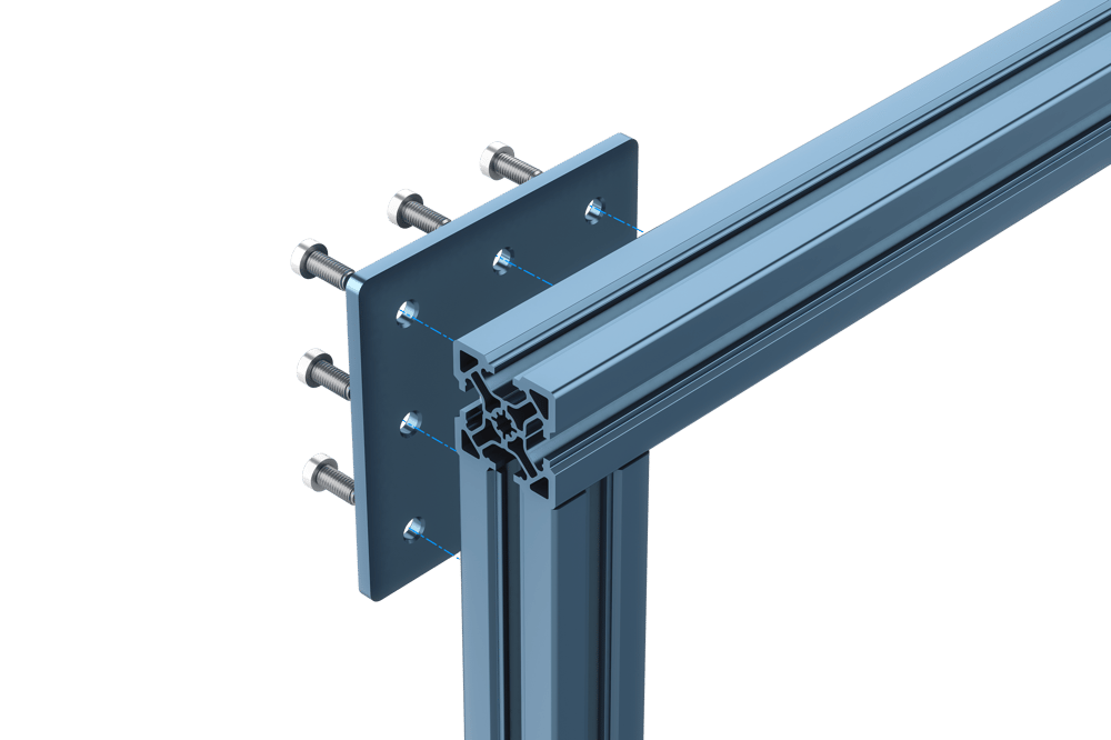
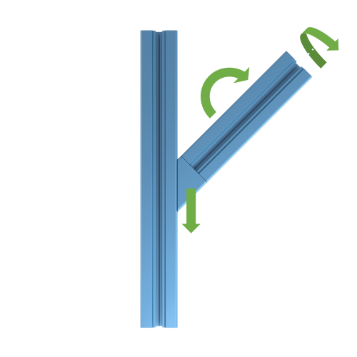
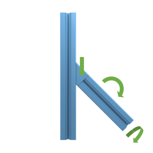
Avoid relying on friction-based joints to support the load. Instead, position one extrusion on top of another, as shown below. Force is transmitted directly from the horizontal extrusion to the vertical extrusion increasing strength.
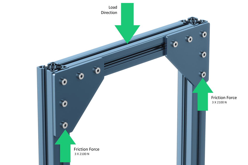
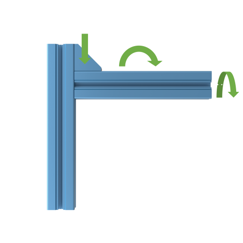
❌ Friction joint (not recommended): Lower strength; force transmitted through friction between plate and extrusion.
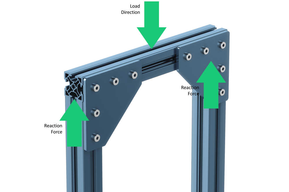
✔️ Reaction force-based joint (recommended): High strength; force transmitted directly to the frame via contact with vertical extrusions.
When friction-only joints are unavoidable, the strength of the joint is dependent on the number of fasteners multiplied by each fastener’s friction force. Each Vention M8 fastener (the type used in extrusions) can support 2100 N in friction.
In the friction joint example above, each fastener can generate 2,100 N of friction when tightened to 13 Nm, the horizontal beam can support a maximum load of 12,600 N (that is, 2,100 N per fastener x 6 fasteners). Consider the total amount of force needed to support your desired load, and divide it by 2100 N to find the number of fasteners you will need. This number will tell you which size assembly plate to choose, from one-fastener plates to eight-fastener plates.
Calculating the necessary assembly plate size is a great way to optimize the cost of your design. You might be tempted to choose the strongest assembly plate available, but you can save costs by going with one that only fits the amount of fasteners you need (and no more). Our application engineers routinely reduce costs by up to 15% just by replacing six-, seven-, or eight-fastener assembly plates for ones with fewer fasteners.
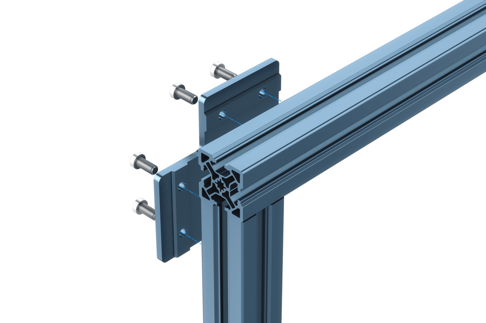
If possible, transform a friction-only joint into a stronger three-way joint by threading one of the fasteners directly into the extrusion’s end. By uniting three different extrusions in such a configuration (i.e., one vertical and two horizontal), none of the plates depend on friction alone.
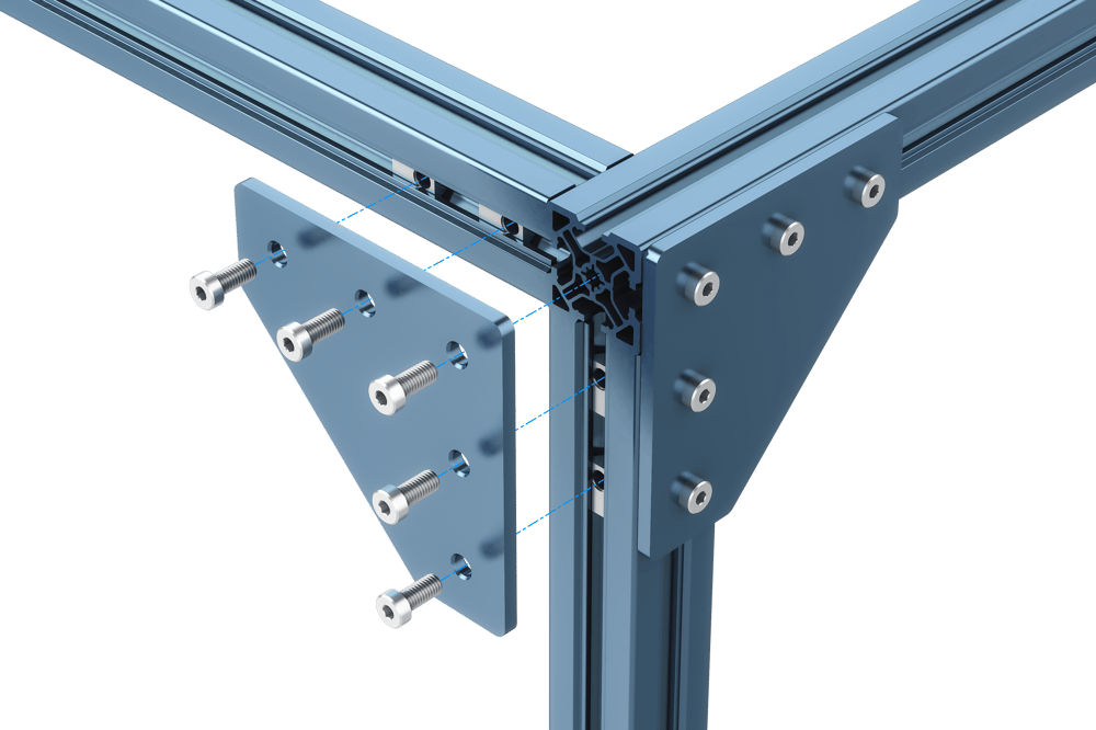
✔️ Strong three-way joint: one bolt threads directly into the end of the extrusion.
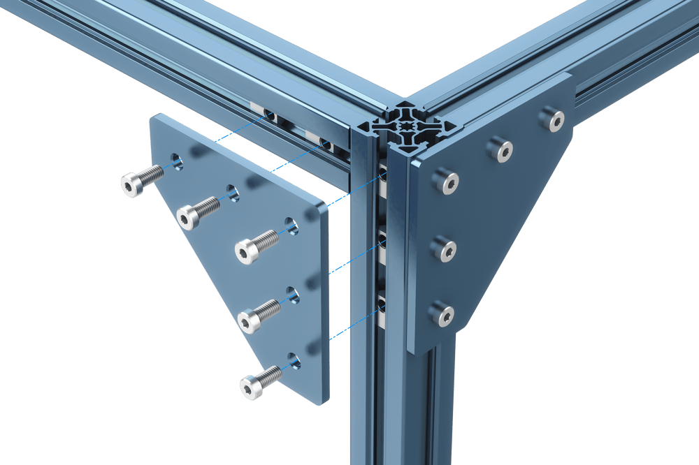
❌ Weak friction-only joint, bolt does not thread into the extrusion end. (These are sometimes unavoidable.)
In some cases, joints may undergo a force that pulls the bolt and t-nut out of the extrusion. The extrusion’s resistance to this force is what we call “pull-out strength.” This “ultimate strength”—the point at which complete failure occurs—is given on a per-fastener basis.
For Vention V2 extrusions, the ultimate strength is 16.7 kN. However, designs should not be based on this value, because even much lower values can permanently damage the extrusion.
We recommend a design value of 7.2 kN per fastener. This value is lower than the material’s yield point, so no permanent deformation will occur. As with all design values, remember to apply a safety factor.
Ultimate strength is also affected by the direction of load. Whereas bolted connections under tension will fail when the pull-out strength is exceeded, compressed connections can withstand much higher loads, because the force is directly supported by the extrusion. As shown below, placing the assembly plate correctly with respect to the load will maximize strength.
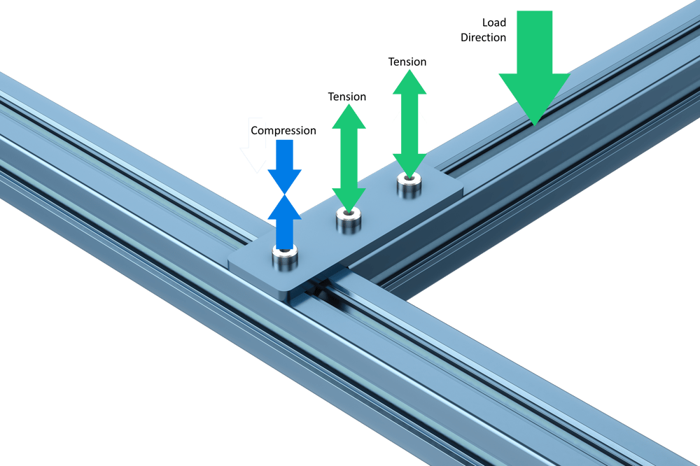
Max load is 2 x 7.2 kN, because two bolts are sharing the tensile load.
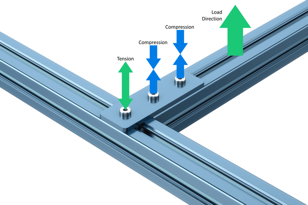
Max load is just 1 x 7.2 kN, because one bolt is supporting the entire tensile load.
3. Use high-strength extrusion systems for demanding applications
Combining effective assembly joints with the appropriate extrusion profile can improve the structural integrity of your assemblies. For heavy-duty or precise applications, Vention’s high-precision assembly plates (part numbers ST-HP-XXX-XXXX) feature a patented V-shaped boss (protrusion) on the plate underside.
- Eliminates angular misalignment, because it is no longer necessary to locate plates by their screw’s loose clearance holes.
- Increases slippage resistance, by converting friction-bonded joints to structurally bonded joints.
Many plates come in GP (general purpose) and HP (high precision) variants. Your choice depends on whether you want to optimize for lower price (GP) or higher strength and precision (HP).
4. Structural joint design guide
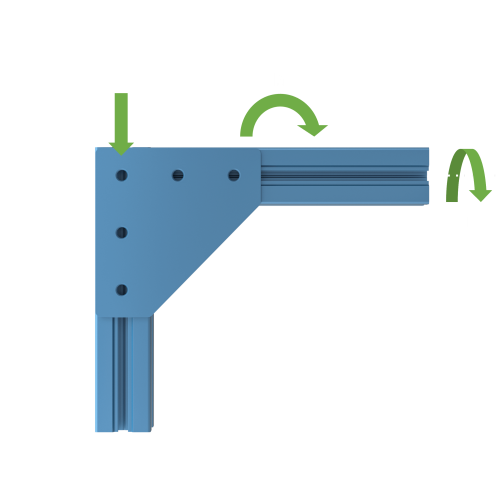
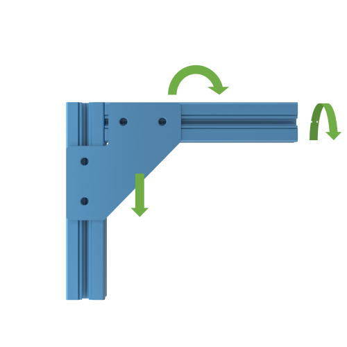
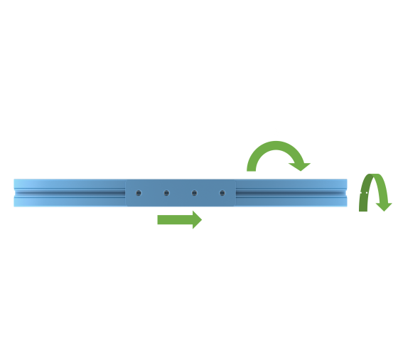
Use the following tables to determine the strength of single sided jointed connections when subjected to moment, torsion and friction forces. The values are valid for the following assumptions:
- For moment loading, the load is created by a vertical force applied on a beam 1000 mm from the joint.
- All bolts are assumed to be torqued to 10-13Nm.
- For friction loading, the load is created by a vertical force directly on the joint, with negligible torsion or moment.
- Given values are valid for structural extrusions: ST-EXT-001-XXXX, ST-EXT-002-XXXX, and ST-EXT-005-XXXX.
- Values indicate when permanent slippage or plastic deformation begins to occur. This is the point where permanent damage starts, and should be avoided by using a safety factor.
** Important: Determine safety factors according to your industry’s standards. Always increase the safety factor if there is any risk of injury occurring due to system failure</strong>. A safety factor of 4-5 is suggested.
| Gussets | 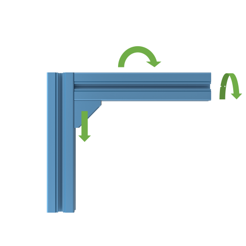 ST-GP-003-0001 / ST-HP-003-0001* |
 ST-GP-003-0001 / ST-HP-003-0001* |
 ST-GP-003-0001 / ST-HP-003-0001* |
|---|---|---|---|
| Friction, F (N) GP / HP |
2100 / 2100 | 2100 / 2100 | Buckling Failure** |
| Moment, M (Nm) GP / HP |
127 / 127 | 112 / 112 | 127 / 127 |
| Torsion, T (Nm) GP / HP |
0 / 100 | 0 / 100 | 0 / 100 |
| Plates | 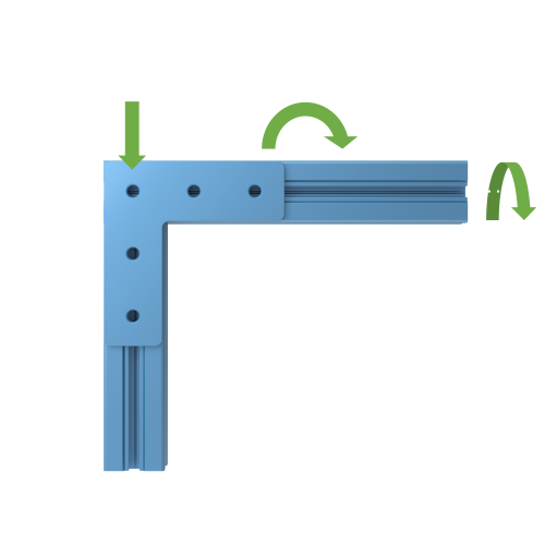 ST-GP-001-0005*** |
 ST-GP-003-0001*** |
 ST-HP-001-0001*** |
|---|---|---|---|
| Friction, F (N) | 6300 | 6300 | 4200 |
| Moment, M (Nm) | 235 | 725 | 325 |
| Torsion , T (Nm) | 70 | 85 | 45 |
| Other | 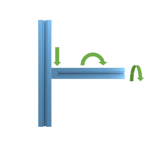 ST-GP-002-0001 |
 ST-GP-001-0004*** |
 ST-HP-001-0001 |
 ST-HP-001-0001 |
|---|---|---|---|---|
| Friction, F (N) | 4200 | 4200 | 2100 | 2100 |
| Moment, M (Nm) | 100 | 215 | 100 | 500 |
| Torsion, T (Nm) | 165 | 65 | 390 | 390 |
*: These configurations assume no contact between the extrusions, which is common in assembled structures.
**: This configuration is more dependent on a buckling failure mode than friction. Use the calculation methods for buckling shown in Section 1 of this .
***: The values for these configurations are for joints fixed by an assembly plate on a single side.
Conclusion
Aluminum t-slot extrusions have become a compelling alternative to welded steel for many applications, but they require a few design considerations. If you need any help with your project, or simply want to confirm some design parameters, you can ask our team of application engineers for free using Vention’s live chat or email us at: support@vention.io
Vention V1 extrusion properties
| Part Number | Length range (mm) | Yield strength (MPa) | Area moment of inertia (mm^4) | |
|---|---|---|---|---|
| V1 45x45mm Aluminum Extrusion | ST-EXT-001-XXXX | 45–2,295 | 140 | 154,260 |
| V1 45x90mm Aluminum Extrusion | ST-EXT-002-XXXX | 45–3,330 | 140 | 1,105,496 Ix*** |
| V1 90x90mm Aluminum Extrusion | ST-EXT-005-XXXX | 45–3,330 | 140 | 1,840,143 |
*Area moment of inertia (or the second moment of area) describes a profile’s resistance to beam bending. A higher value indicates less deflection.
***Note: The 45 x 90 mm and 22.5 x 180 extrusions’ moment of inertia depend on the extrusion’s orientation.