Safety Enclosure Ecosystem
Contents
- Overview
- Applications
- Safety
- Machine Guarding Panels (ST-PN-002-0700/1000/1200)
- Enclosure Doors
- Floor Anchors (ST-SE-001-0005)
- Two Way Door Connector
- Safety Interlock and Gate Bolt (ST-SE-006-XXXX)
- Safety Interlock Switch (CE-SA-010-0000)
- Spring Loaded Grab Catch
- Emergency Stop Switch (CE-SA-007-0000)
- Wiring Diagram
Overview
Vention’s safety enclosure ecosystem features all the necessary components to quickly deploy a complete safety fencing system or robot cell that integrates directly with the MachineMotion’s safety rated input. In this technical document the following will be covered: safety panels, doors, anchoring, interlocks and safety.
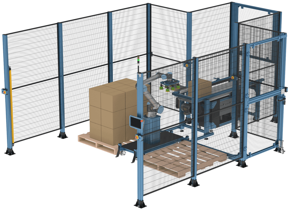
Applications
The typical applications include enclosures for robot cells and automation equipment. The enclosure is used to contain the risk and prevent workers from entering a high risk zone. Take a look at Vention’s public designs for some inspiration.
Safety
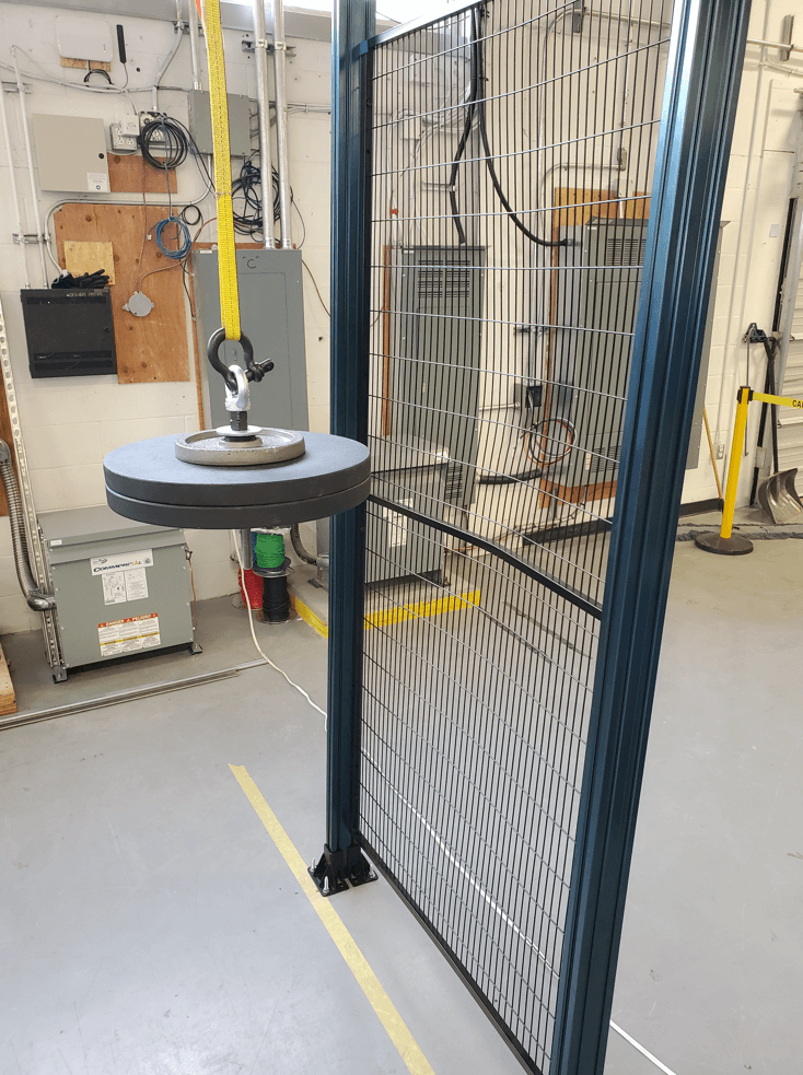
Mechanical Testing
Our current enclosure hardware offerings have been validated to contain impact energies typically seen of industrial robots with a payload of 50kg or less. The machine guarding panels, doors and anchors seen below have been tested in accordance with:
ISO 14120, Safety of machinery – Guards - General requirements for the design and construction of fixed and movable guards
Which defines the pendulum test method for mechanically testing the guards.
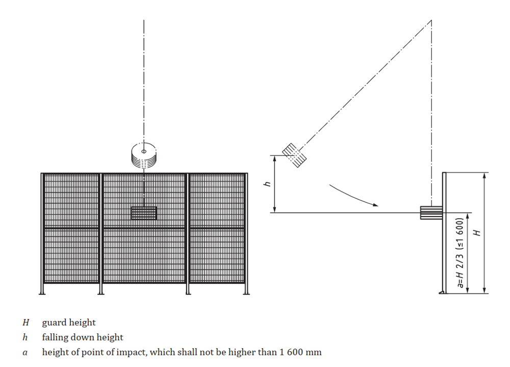
This test was performed in our R&D center with the following inputs:
| Input Parameters | |
|---|---|
| Test Materials | 2050 x 1000mm machine guarding panel (ST-PN-002-0700/1000/1200), wire mesh panels (ST-PN-002-0004/0005) held in place using panel retainers (ST-PN-007-0001), 45 x 90mm extrusions supporting columns (ST-EXT-002-2205), welded steel anchors (ST-SE-001-0005), personnel access door, pallet bay access door, safety interlock (ST-SE-006-XXXX) |
| Floor fixing | Four 3/8” x 4” expansion anchors per supporting column |
| Guard height (H) | 2205 mm |
| Falling height (h) | 1700 mm |
| Impact height (a) | 1470 mm |
| Pendulum mass | 45 kg |
| Impact speed | 5.5 m/s |
| Impact energy | 750 J |
*Refer to MachineBuilder designs for full product definition and BOM
The test is considered a pass if it respects the following conditions as defined by ISO 14120:
- The deformations or cracks do not exceed values specified to avoid harm,
- There is no penetration,
- The guard window or infill material is not loosened from its fixing, and
- The guard is not loosened from its guard support
All tests conducted successfully withstood the high energy impact. The center of the panels and posts absorbed all energy and sustained plastic deformation. Total deflection was that whereby no penetration or removal of parts occurred.
Installation and Assembly
The safety enclosures shall be installed according to the assembly instructions and according the requirements of:
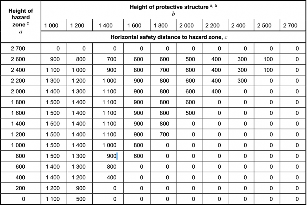
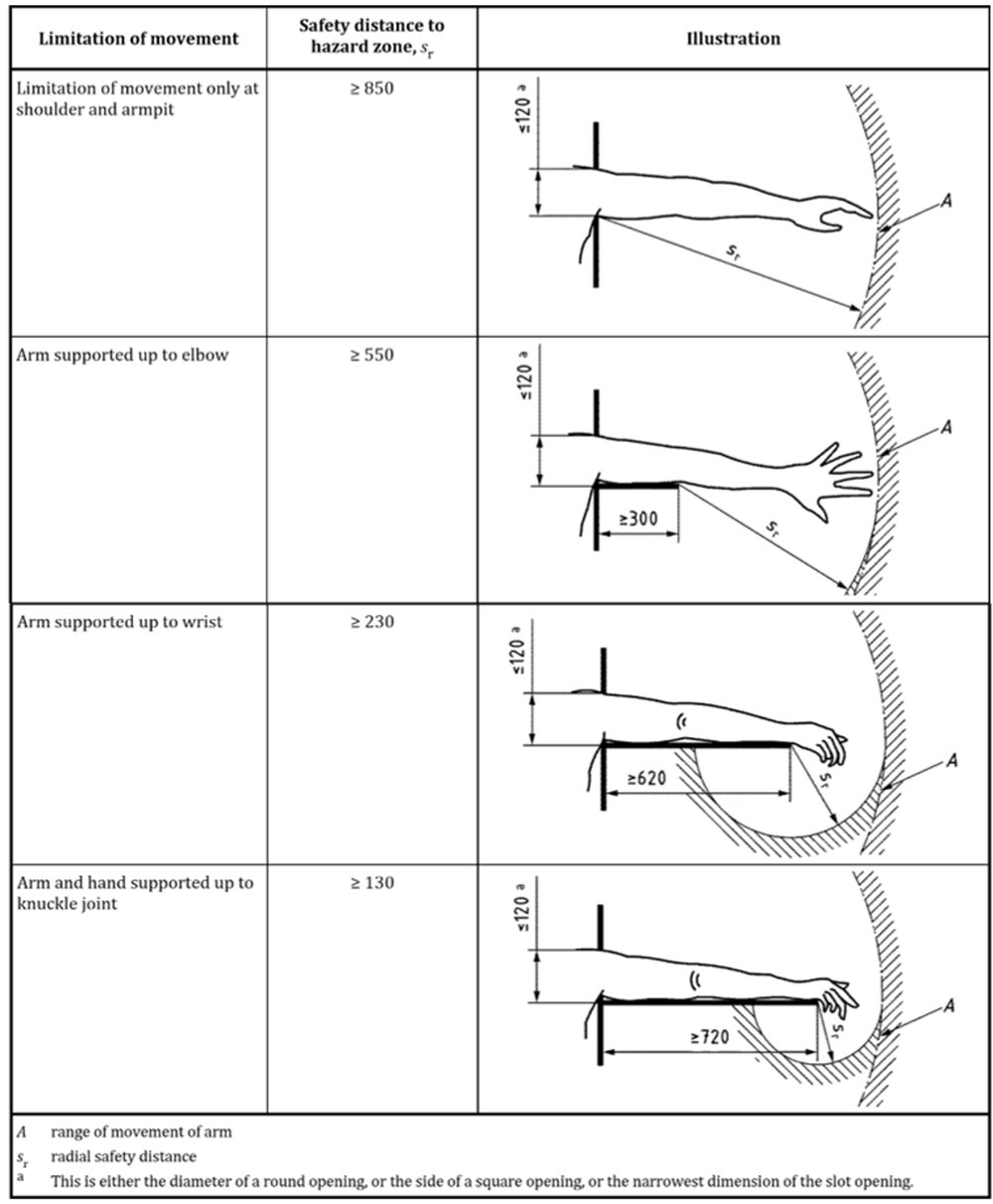
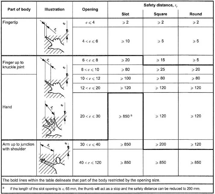
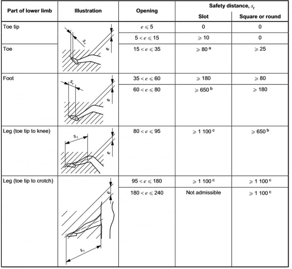
ISO 13857, Safety of machinery – Safety distances to prevent hazard zones being reached by upper and lower limbs, and
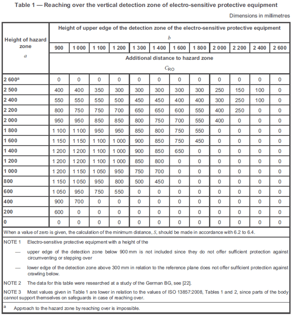
ISO 13855, Safety of machinery – Positioning of safeguards with respect to the approach speeds of parts of the human body.
The safety distance to prevent reaching hazards over the safety enclosure or through its openings is calculated according to the requirements of ISO 13857.
Machine Guarding Panels (ST-PN-002-0700/1000/1200)
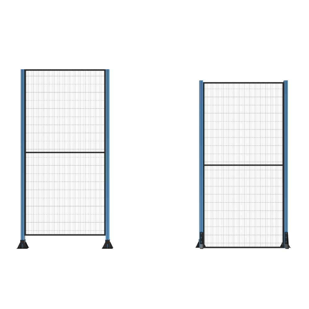
The default safety panels used to create Vention enclosures are constructed with a 19 x 19 mm powder coated steel frame. All horizontal wires are welded into the frame and the vertical wires are welded to the cross tubes, creating a stable and impact resistant panel.
Panel Assembly
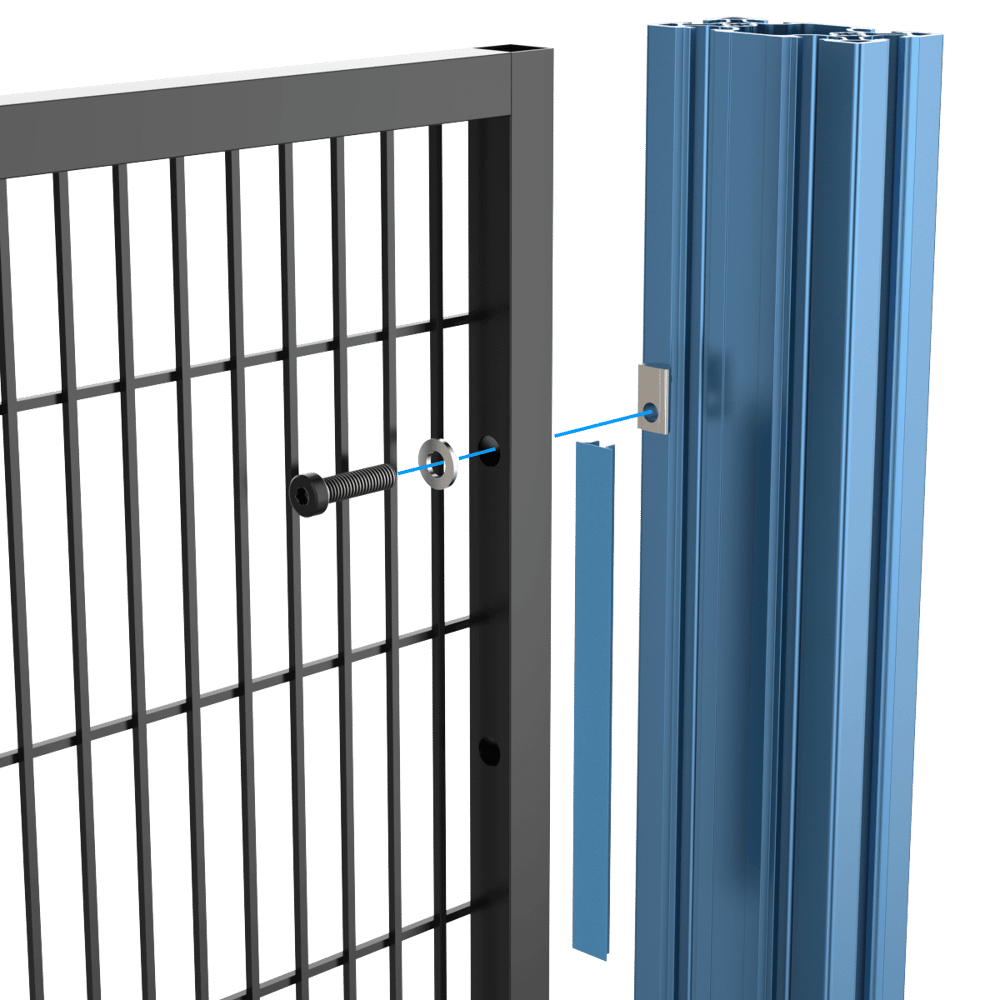
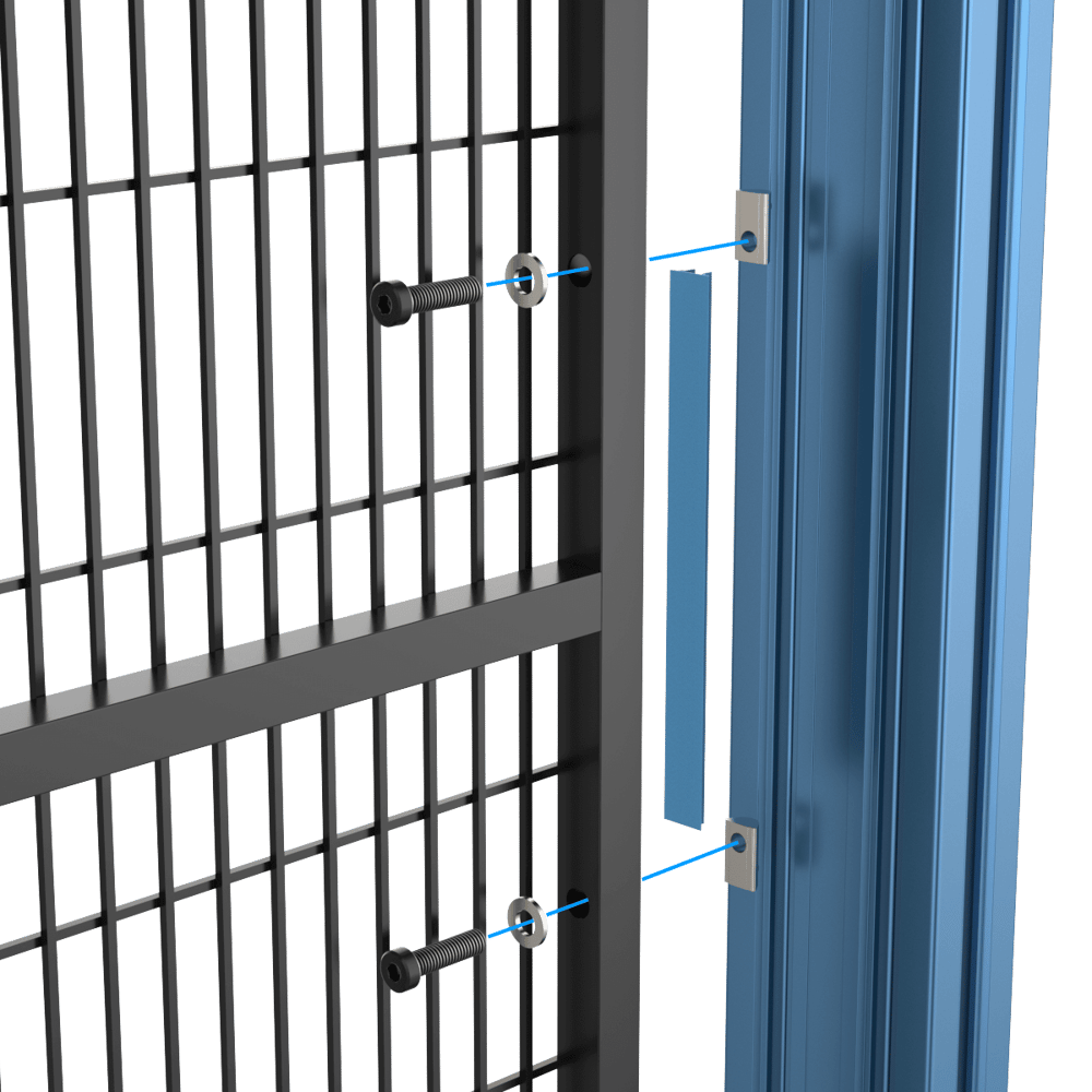
Multiple M8 clearance holes on the vertical panel frame tubes permit easy mounting to the extrusion posts. Each panel will ship with eight M8 x 30mm bolts, washers and t-nuts, as well as six 180mm long segments of t-slot cover. We recommend installing the fasteners on the upper and lower most holes as well as the two center most holes on each side of the panel.
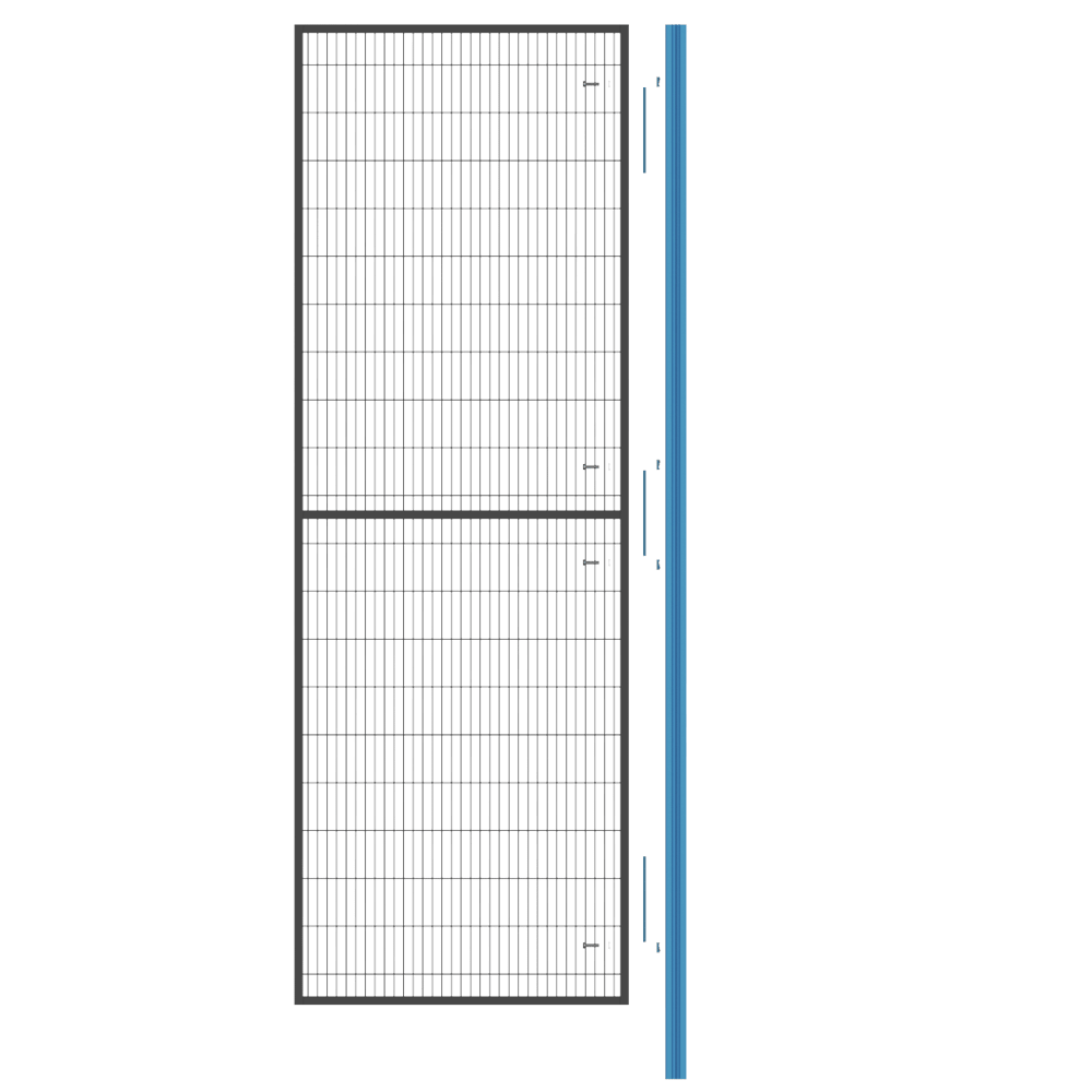
The included t-slot covers will serve to square up the panel up against the extrusion when tightened in placed. They are to be installed right next to the t-nut in the case of the upper and lower mounting holes, and in the middle of the two center mounting holes. Not installing the t-slot covers will cause the panel to slip in the the HP feature of the extrusion resulting in the panel not sitting perpendicular to the post when tightened.
Panel Specifications
| Height of Panel | 2050 mm |
| Width of Panel | 700, 1000, 1200 mm |
| Mesh Opening | 20 x 100 mm |
| Wire Mesh Diameter | 3.12 mm (⅛ in) |
| Required Extrusion Posts | ST-EXT-002-2205 (45 x 90 x 2205 mm) |
| Included Hardware per Panel | 8x HW-FN-003-0030, 8x HW-FN-002-0001 |
| Allowable Impact Energy | 750J |
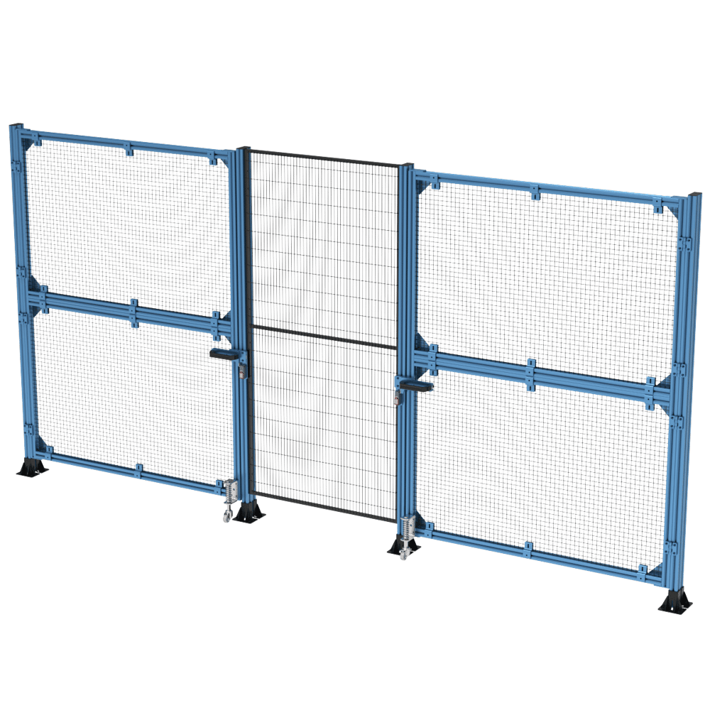
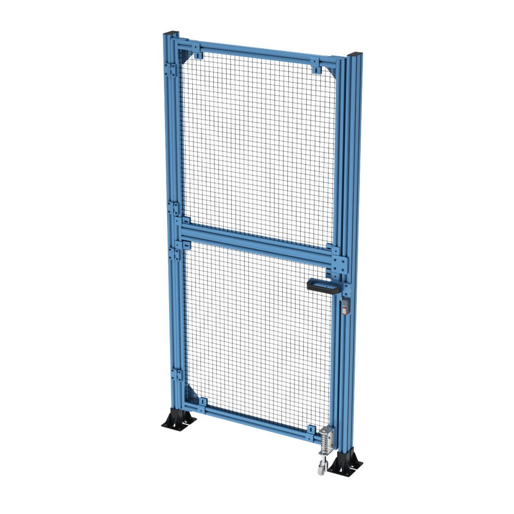
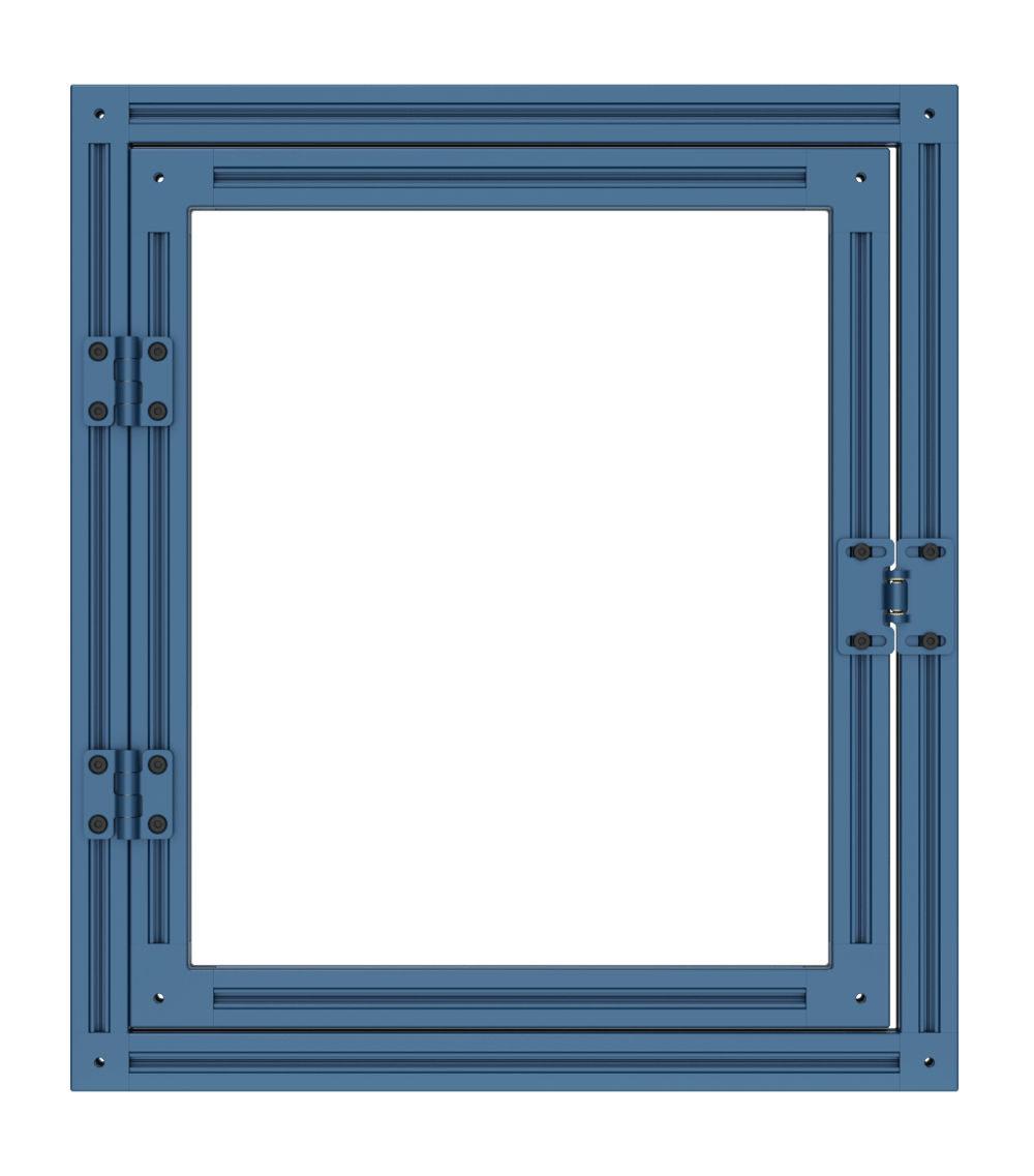
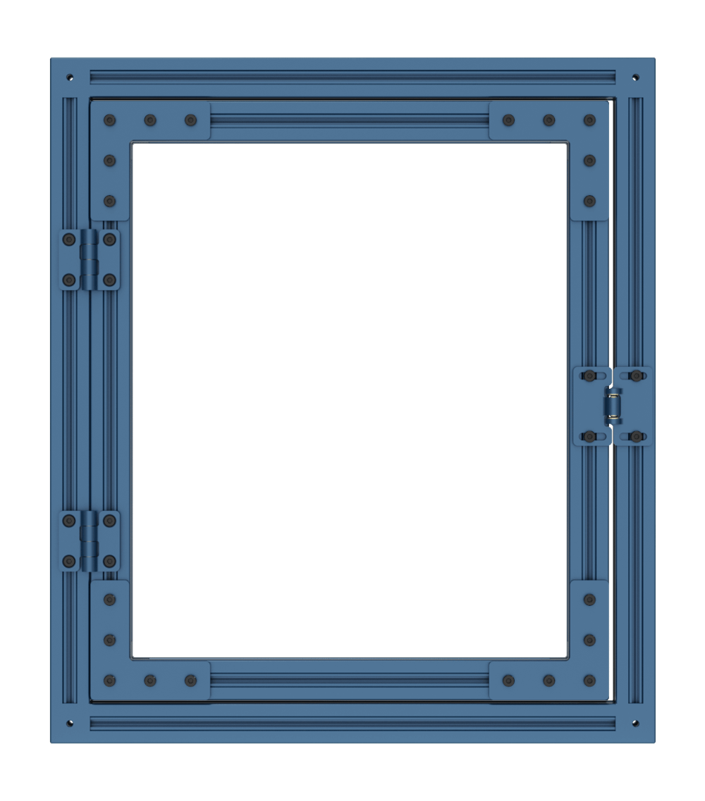
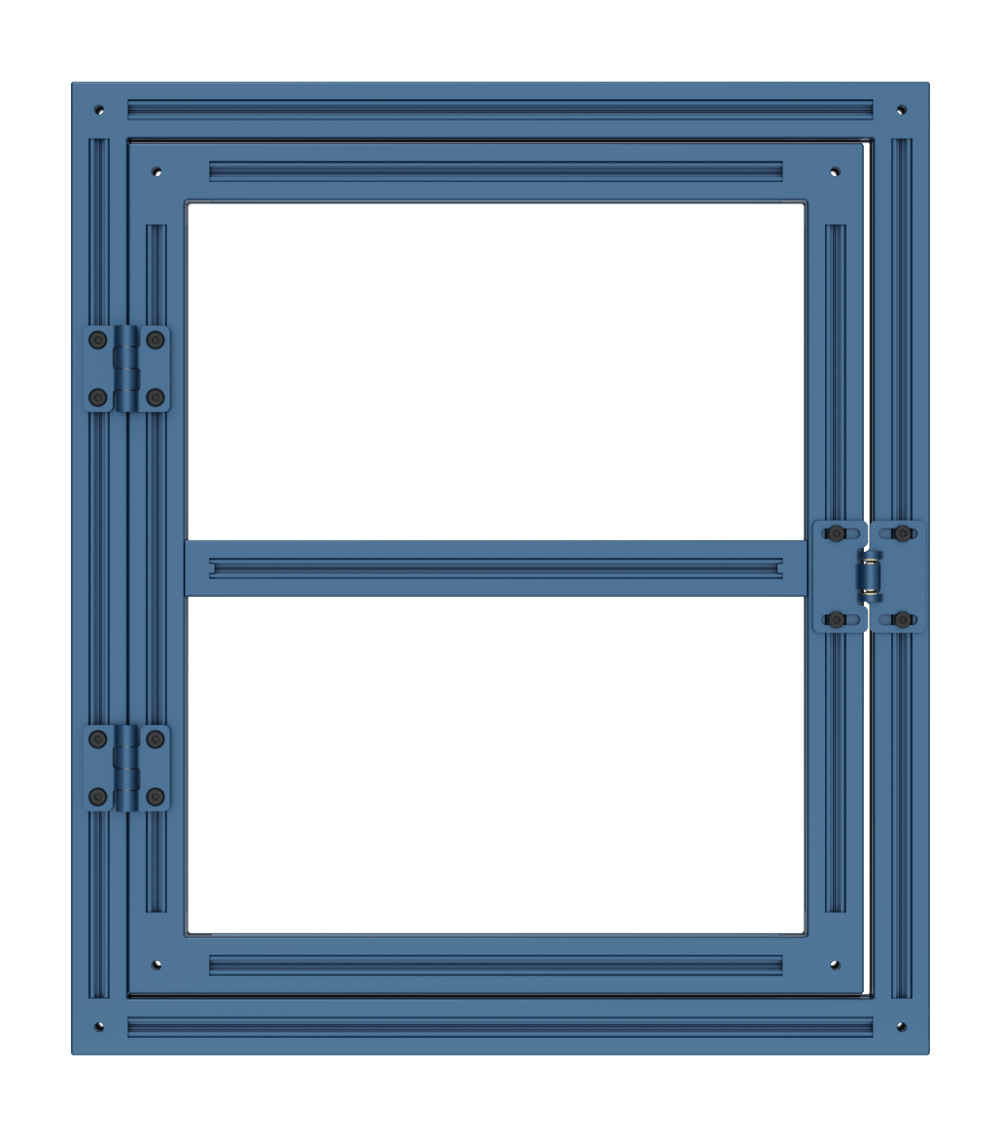
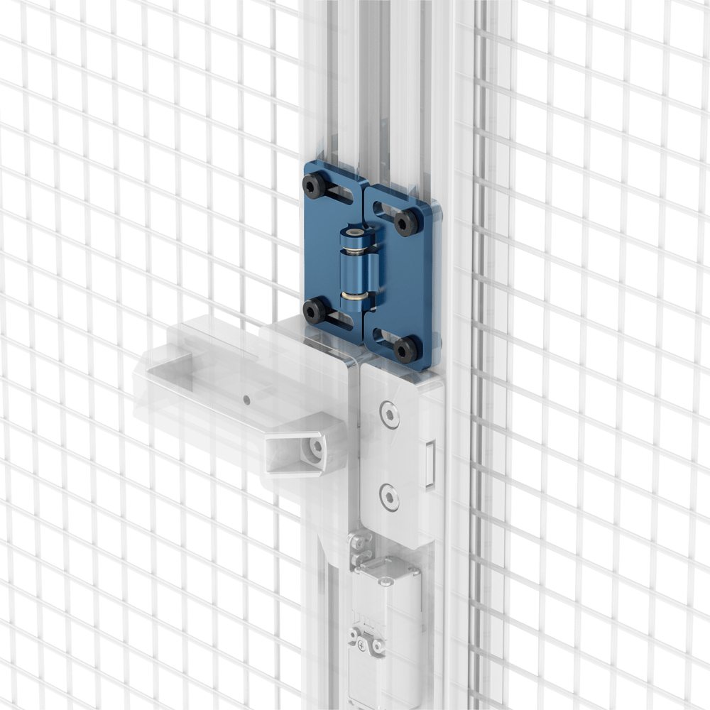
Enclosure Doors
The entry of your safety enclosure can be constructed by using extrusions to build a door. This main structure can be constructed from 45 x 45 mm light-duty extrusions with an array of assembly plates to hold it all together. One side supported by the Vention Door Hinge (ST-SE-005-0001), allowing for full 180 degree opening. A single simply supported hinge can support up to 600kg in pure shear. A door with 2 hinges can support a moment up to 1000 N⋅m in bending. The other side of the door can be held closed by the Vention Gate Bolt. Depending on the level of safety required by the safety enclosure, an interlock can also be installed on the door as either part of the Gate Bolt (ST-SE-006-XXXX) or a stand alone Safety Switch (CE-SA-010-0000). To simplify the sizing of the doors, two ready to ship wire mesh panel sizes have been added to the platform to size the door either for pallet bays or personnel/emergency access. The 2 mesh panel sizes are as follows:
- 920 x 965 mm (ST-PN-002-0004)
- 1505 x 965 mm (ST-PN-002-0005)
To retain the mesh panels as well as meet the requirements of the ISO 14120 impact test, six panel retainers (ST-PN-007-0001) need to be used per panel; with two per horizonal extrusion, and one per vertical extrusion, spaced equally.
For access to the gate bolt release, cutouts can be made and the sharp edges protected with rubber edge trimming (ST-PN-014-0002).
The renders below may not fully represent a final installation but should give an idea as to the overall assembly for each of the enclosure doors.
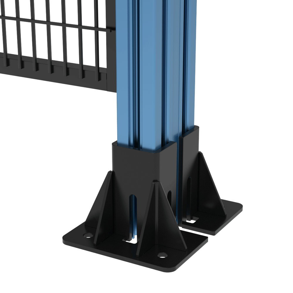
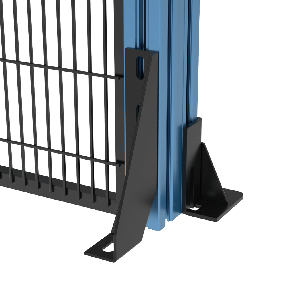
Floor Anchors (ST-SE-001-0005)
Anchors used for machine guarding are vital in ensuring containment of energy. The gusseted design of these anchors will create a lot more stability for loads transferred through the extrusion posts. It can be used with our 45 x 45mm profile but is most rigid mounted in pairs on a 45 x 90mm extrusion profile. Three slots are provided to attach the anchor to the extrusion post with bolts and t-nuts. The slots have been designed in a way for the bolts to be partially pre-threaded into the t-nuts and then to allow the anchor to be slid over them after for easy installation. The anchoring holes on the base plate are clearance-sized for 3/8” diameter anchors.
Alternate Anchoring Configuration for Reduced Safety Distance
An alternate anchoring configuration has been tested and validated under the same impact energy for use cases where the respected safety distance is less than 650mm. This configuration makes use of the Machine Guarding Floor Anchor (ST-SE-001-0005) on the inner side of the enclosure (the high energy side) and the Leveling Foot Floor Bracket (HW-LF-001-0004) on the outer side of the enclosure. This will permit for the panel to be lowered to less than the 80mm opening required to respect the 650mm safety distance.
Two Way Door Connector
When a Two-Way Extended Door Connector (ST-GP-004-0006) is used to create a door frame with an interlocking part such as a Spring-Loaded Grab Catch (HW-LT-002-0001), Gate Bolt (ST-SE-006-0001__2) or Safety Interlock switch (CE-SA-010-0000) on the edge, stiffeners must be used.
The figure on the left side illustrates an example of a non-rigid door with an interlocking part. The middle figure shows an arrangement of four L-Shaped Aluminum Assembly Plates (ST-GP-001-0005) that can be mounted in each corner to achieve increased frame stiffness. L-Shaped plates are to be installed over the 2-way door connector, however only three bolts will fit, this is correct. Alternatively, as shown on the right side figure, a cross brace can be created by fastening two 45mm x 45mm Door Spacers (ST-GP-002-0006) on each end of an extrusion which will also increase stiffness.
Safety Interlock and Gate Bolt (ST-SE-006-XXXX)
A safety interlock is recommended in order to properly secure your safety enclosure door, when activated it will immediately power off all actuators connected to the MachineMotion controller.
Vention’s gate bolt is available with or without a safety interlock tongue and groove system and features an adjustable slide with an anti-vibration system so you don’t have to worry about your gate bolt and door unintentionally opening.


The gate bolt comes in four variants, a right (ST-SE-006-0001__2 ST-SE-006-0011__2) and a left (ST-SE-006-1001__2 or ST-SE-006-1011__2), with or without an interlock included. Both feature the same allowable door gap and the versions with interlock included have the following specifications. Gate bolts with interlock also include a 5-meter M12 4-Pin extension (CE-CA-102-5001__2).
Vention’s lockable gate bolt and interlock, available in right (ST-SE-006-2001) and left (ST-SE-006-2002) configurations shown below, are used in conjunction with Access Request Module (CE-SA-017-0001) to allow for full deactivation of your industrial robot cell until the gate is properly closed. Lockable gate bolts with interlock also include a 5-meter M12 4-Pin extension (CE-CA-102-5001__2).
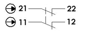
Interlock Specifications
| Allowable Door Gap | 0 to 22.5mm |
| Interlock Contact Configuration | 2 N.C. (Normally Closed) Contacts |
| Interlock Connector | Male M12 4-Pin |
| Force for Opening [N] | 12N |
Note: A 90x90 Rest Pad (HW-RP-002-0006) can be used as a door stopper to prevent the gate from swinging inwards.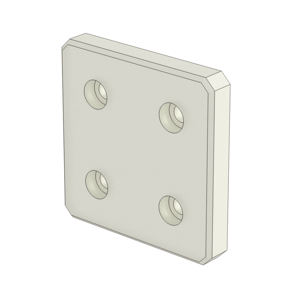
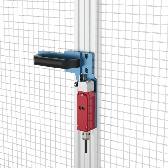
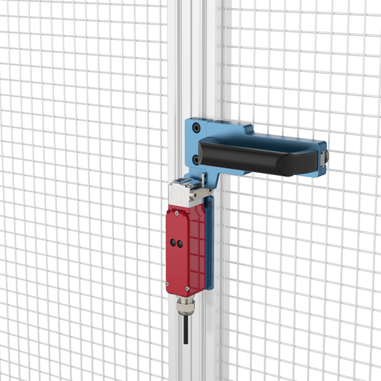
Safety Interlock Switch (CE-SA-010-0000)
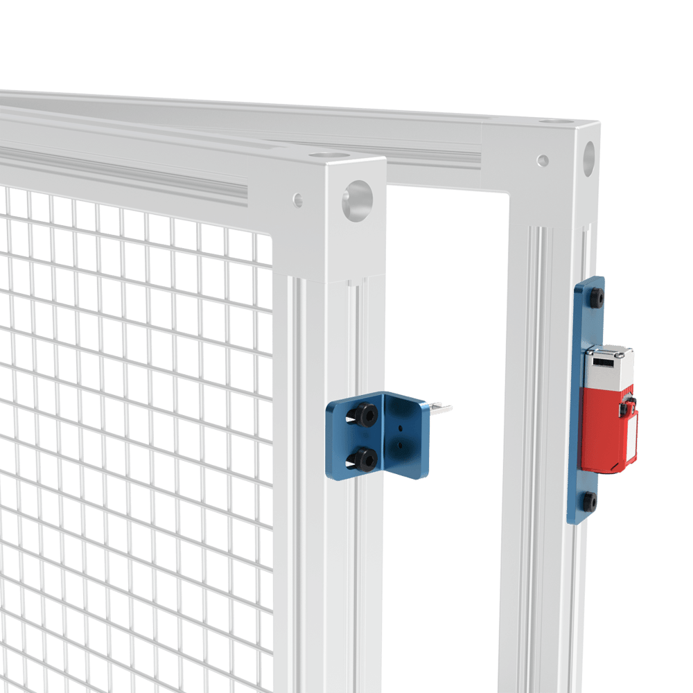
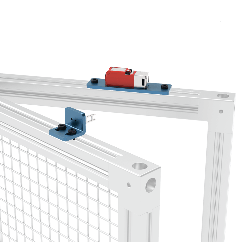
For a door with a 22.5mm gap, a Safety Interlock Switch (CE-SA-010-0000) with a door catch can be used as a substitute. The switch and groove mechanism features the same Interlock as the Gate Bolt with identical specifications. A door stopper is included and the entire assembly is fully reversible for left/right opening.
Note: When creating a door assembly, the door must be wider than 150mm to allow the tongue to properly enter the interlock.
Interlock - Pin-out - M12, female, 12-pin, A-Keyed, with adapter

| Pin | Description | Color |
|---|---|---|
| Pin 3 | Channel 1 Contact 1 | White |
| Pin 4 | Channel 1 Contact 2 | Green |
| Pin 5 | Channel 2 Contact 1 | Pink |
| Pin 6 | Channel 2 Contact 2 | Yellow |
Interlock - Pin-out - M12, female, 4-pin, A-Keyed, without adapter
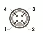
| Pin | Description | Color |
|---|---|---|
| Pin 1 | Channel 1 Contact 1 | Brown |
| Pin 2 | Channel 2 Contact 2 | Blue |
| Pin 3 | Channel 1 Contact 2 | White |
| Pin 4 | Channel 2 Contact 1 | Black |
For any questions about creating a custom Vention assembly for your application contact our application engineers via a design review.
Spring Loaded Grab Catch
The Vention spring-loaded grab catch (HW-LT-002-0001) can be used in conjunction with the gate bolt, safety interlock or alone. When used with 45mm extrusions, the allowable gap is 0 to 22.5mm. For 22.5mm extrusion doors the allowable gap is 22.5 to 45mm.
Note: A rest pad is still required to prevent the gate from swinging inward. Also, place the grab catch close to the door handle otherwise the door will not open or close smoothly.
Emergency Stop Switch (CE-SA-007-0000)

A Emergency Stop Switch is recommended in order to immediately power off all actuators connected to the MachineMotion controller. The Emergency Stop Switch must be connected to the MachineMotion Safety-In port. Multiple emergency stop switches can be connected to a single MachineMotion using the Safety-In and Safety-Out ports on the switch. If only one switch is used the included jumper should be connected to the Safety-In port on the switch.
Wiring Diagram
The interlock on the Safety Switch (CE-SA-010-0000) or Safety Gate Bolt (ST-SE-006-0001__2 or ST-SE-006-1001__2) comes with a safety wire splitter. The interlock must be connected to the MachineMotion Safety-In port. Multiple interlocks and Emergency Stop Switches can be connected to a single MachineMotion using the wire splitter provided with the interlock or Safety-In and Safety-Out ports on the switch. If only one interlock is used the included jumper must be connected to the unused port.

Switch - Pin-out - M12, female, 12-pin, A-Keyed
| Pin | Description | Color |
|---|---|---|
| Pin 3 | Channel 1 Contact 1 | White |
| Pin 4 | Channel 1 Contact 2 | Green |
| Pin 5 | Channel 2 Contact 1 | Pink |
| Pin 6 | Channel 2 Contact 2 | Yellow |
| Pin 7 | Reset Contact 1 | Black |
| Pin 8 | Reset Contact 2 | Gray |