Universal Robot - Robot Configuration for MachineLogic Applications
Overview
Vention now offers Universal Robot Programming directly in MachineLogic alongside Vention actuators directly in Vention’s pendant. With a few extra steps, you can deploy your robot enabled program in minutes.
This document describes the steps necessary to get up and running with Robot Programming in MachineLogic for Universal Robots e-Series, which enables the seamless integration of a UR six-axis robot arm alongside Vention motion components, all while staying in Vention’s no-code environment. Applications like range extenders, cobot palletizers and other custom robot cells, are now possible within the Vention platform.
1. Connect your system
In order to program your UR e-Series Robot in MachineLogic, a Vention MachineMotion 2 Pendant V3 (CE-TP-014-0000) and a Vention Robot Safety Module (CE-SA-009-0000) is required, in addition to a MachineMotion v2 (CE-CL-010-0004 or CE-CL-010-0001) running firmware version v2.9.0 or later.
1.1 Universal Robots Safety Configuration and Connection with MachineMotion V2
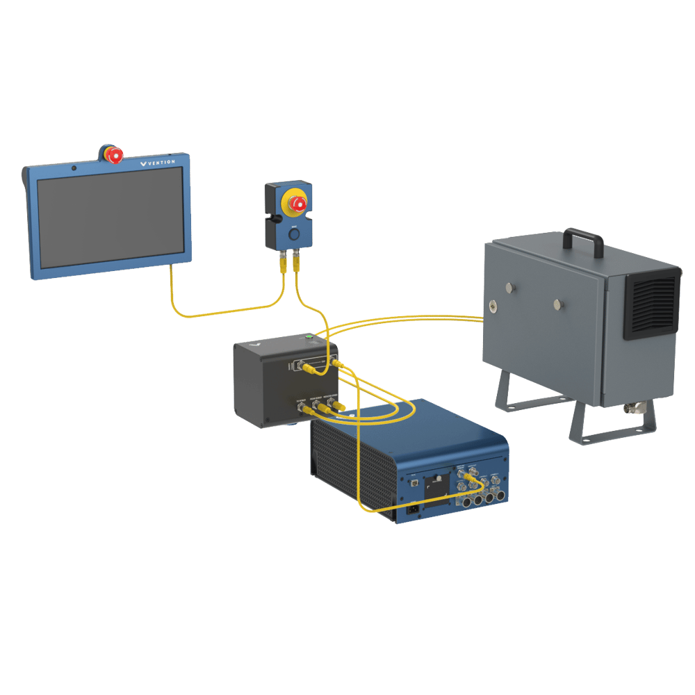
This section describes the connection of a MachineMotion V2 to a Universal Robot controller by way of the Robot Safety Module, in order to program the robot through MachineLogic. The Robot Safety Module acts a 3-port Ethernet switch to enable seamless communication between the MachineMotion, the pendant, and the robot controller (see Figure 1). A first step will also be done in order to properly configure the Safety of the Universal Robot Controller.
To properly perform the Safety Configuration of the Universal Robot controller with a MachineMotion V2, follow the steps detailed in this guide: Universal Robots Safety Configuration with MachineMotion V2.
Once the configuration is completed, make sure that the required safety components are properly connected.
Follow the steps detailed in the Robot Safety Module User Manual.
A typical installation (Figure 1) will require the following components:
-
MachineMotion Pendant V3
- Firmware Version v3.0 or later
- E-Stop Module with Reset
- Robot Safety Module
- UR Robot Controller
-
MachineMotion 2 - Four Drive or MachineMotion2 - One Drive
- Firmware Version v2.9.0 or later
- 3 x MachineMotion 2 Safety Extension Cable – 5m (CE-CA-102-5001)
NOTE: If your system has more than one controller set up in a Multi-Controller configuration, the safety chain which includes the Robot Safety Module and the Pendant must be connected to the parent controller.
1.2 Configuring up the UR controller’s Network
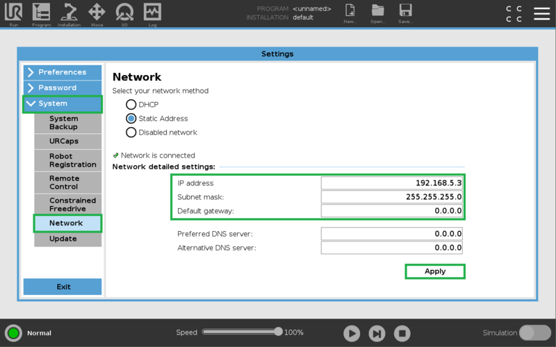
On the UR teach pendant home screen, select Menu > Settings > System > Network. Select Static Address as your network method & change the IP address to 192.168.5.3, Subnet mask to 255.255.255.0, and Default Gateway to 0.0.0.0 (see Figure 2a & 2b).
Preferred DNS server to 0.0.0.0 and Alternative DNS server 0.0.0.0. Select Apply when done.
2. Pre-connection Setup on UR controller
2.1 Installation of the External Control URCap on the UR controller
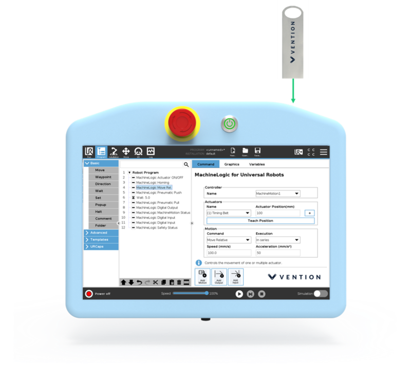
Step 1: Insert the USB drive
Vention’s External Control URCap software is distributed on a USB flash drive and must be installed on the UR teach pendant before continuing onto working in the Vention pendant. To install the URCap, insert the USB drive into the UR teach pendant’s USB port.
Note: You can also download the URCap via the following link and upload it to your own USB stick.
Step 2: Add the External Control URCap to the UR environment
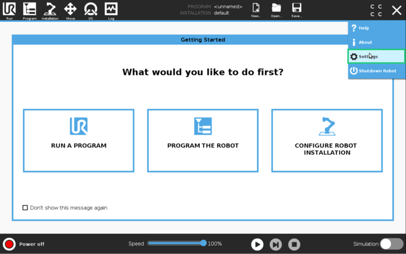
On the teach pendant home screen, select Menu > Settings (see Figure 4a).
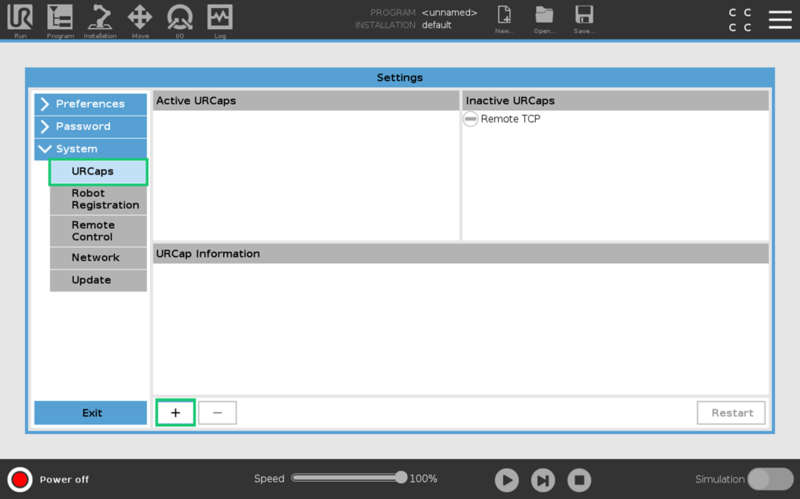
Select System > URCaps, then click the + icon at the bottom of the screen to add a new URCap to the UR teach pendant (see Figure 4b).
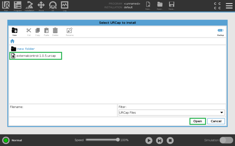
Select the .urcap file and click Open to install the URCap extension (see Figure 4c).
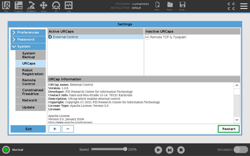
Step 3: Restart the UR controller
When prompted to do so, restart the UR controller to complete the installation (see Figure 5).
2.2 Configuring the External Control URCap
Step 1: Navigate to URCaps Installation Page
On the teach pendant, select Installation > URCaps (see Figure 6).
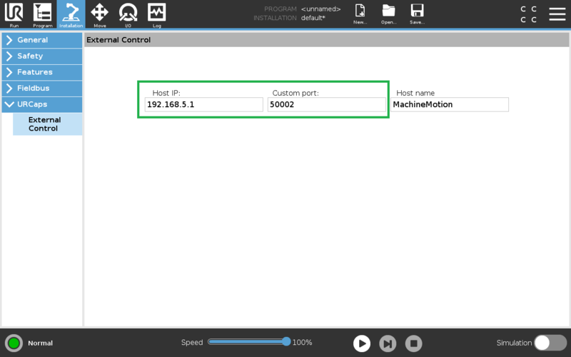
Step 2: Set Host IP and Custom Port
Change the Host IP to 192.168.5.1 and the Custom Port to 50002 (see Figure 7). You may use any Host name desirable.
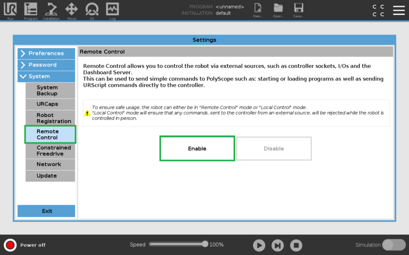
2.3 Enabling Remote Control
On the teach pendant home screen, select Menu > Settings (see Figure 8a).
Select System > Remote Control, then click the Enable (see Figure 8b).
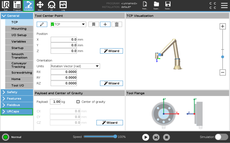
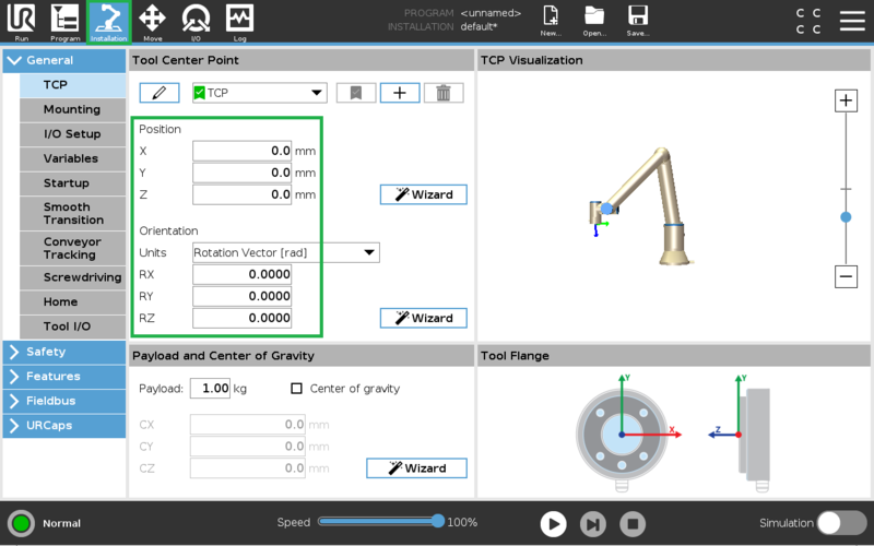
2.4 Verify Tool Center Point (TCP) is Zeroed
The Tool Center Point, or TCP, defines the coordinate system found at the end of the tool mounted to the robot. For Robot Programming in MachineLogic, the TCP, wether an end-of-arm tool is mounted or not, is located directly at the robot’s flange, also known as position 0, 0, 0.
On the teach pendant, select Installation > General > TCP, and verify that all values associated to X, Y, and Z, as well as RX, RY, and RZ, are set to zero (0) (see Figure 9). If not, make the necessary changes.
2.5 Create and Run an External Control program
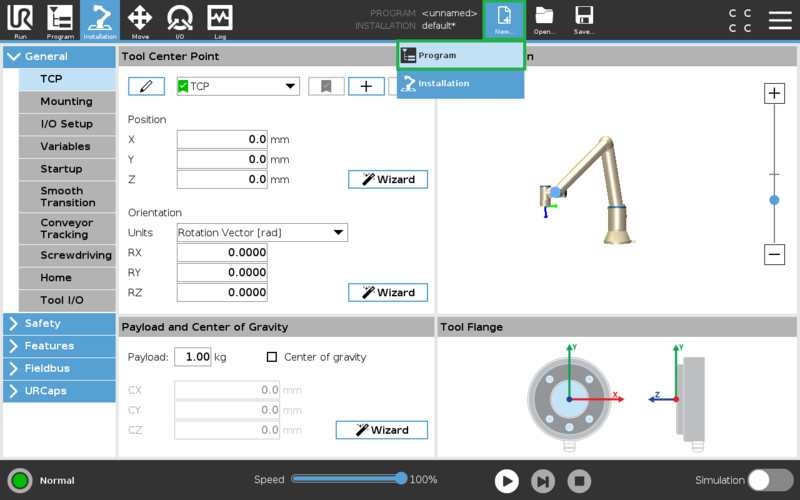
Step 1: Create a new program
On the navigation bar of the teach pendant, select New… > Programs (see Figure 10).
Step 2: Add the External URCap to the program
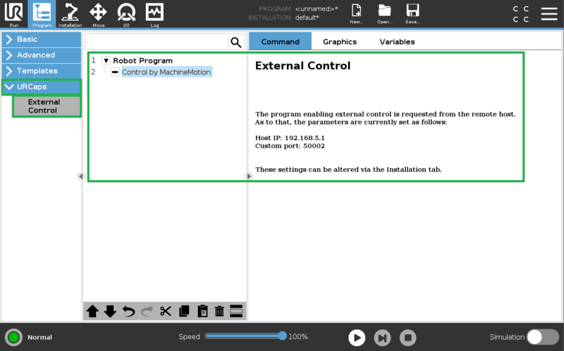
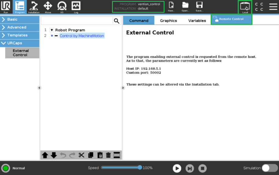
On the left-hand side navigation tree, select URCaps > External Control (see Figure 11). You should see Control by Host name** appear under the program tree view. Verify that the information found on the right-hand side (Host IP and Custom port) match what was set in section 2.2 - Step 2. The program needs to be saved to enable the MachineMotion to control the robot. Save… > Save Program As… vention_control.urp.
NOTE: This step is important and often forgotten. The program name must be exactly named vention_control.urp
Step 3: Change from Local to Remote Control
NOTE: This step is important and often forgotten. The robot controller must be in Remote Control mode for MachineLogic to properly connect.
At the right of the navigation bar of the teach pendant, select Local > Remote Control (see Figure 12).
3. Connecting to the Robot Controller from MachineMotion
With the Universal Robot controller now configured to be externally controlled, you are now ready to deploy your application and configuration from you design on Vention.io.
Follow the steps detailed in the Deploy your Application and Configuration to Controller documentation.
3.2 Troubleshooting
If the robot connection fails (see Figure 16), there could be a few reasons that are the root cause:
- The robot controller is still in Local mode, and not in Remote Control - See 2.5 - Step 3 to enable Remote Control.
- The Universal Robot Program (.urp) is not playing on the robot controller - Make sure everything is properly connected, as the program should play immediately.
- The IP addresses set in 1.2 and 2.2 - Step 2 are incorrectly set. Verify that the correct IP address was entered for both the network and URCap host.
- The Robot Safety Module is not properly wired, not allowing proper communication. Verify your system wiring per section 1.1.
- If a robot has been previously configured and connected, and any of the above occurs, follow the steps shown on the configuration page of the robot.