MachineMotion Pendant Datasheet
Contents
Overview
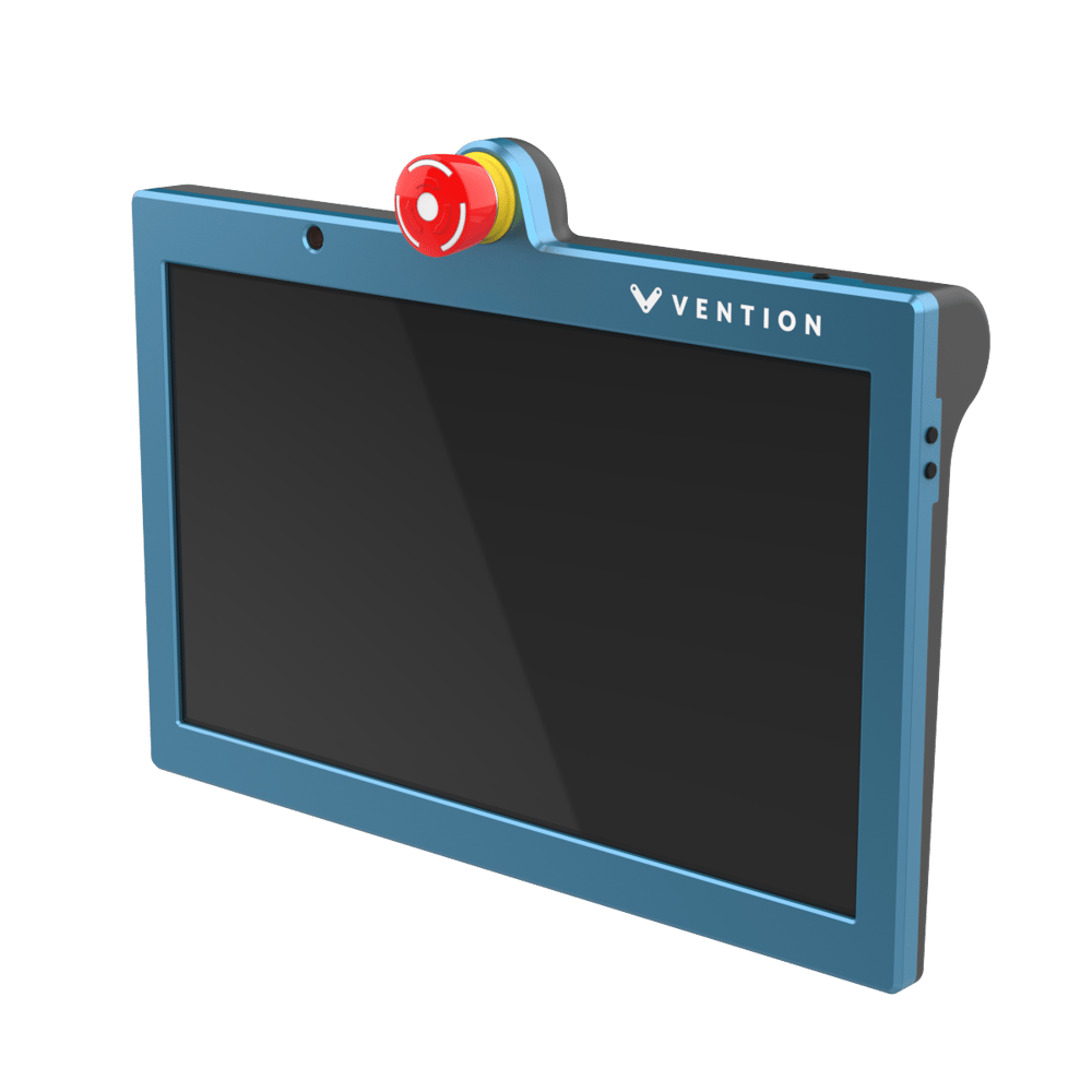
MachineMotion Pendant V3 provides a plug and play touch screen interface for automated equipment powered by Vention’s MachineMotion 2 controller. At 13 inches with two cameras, this Pendant generation is designed to be ergonomically friendly allowing easy operation through a responsive advanced display. When connected to the MachineMotion 2 controller, the Pendant enables machine operators and administrators to run and modify their program in a code-free environment. This product comes with pre-loaded control and machine operations software. Compatible with MachineMotion 2 (CE-CL-010-0001 & CE-CL-010-0004). This datasheet provides technical specifications for Vention’s MachineMotion Pendant V3.2. For details on previous versions, refer to the ‘Documentation for Previous Product Versions’ section at the bottom of this page.
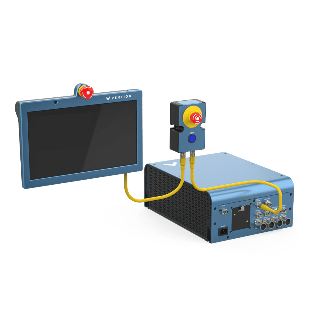
This new version of Pendant includes front and rear cameras for the Remote Support feature. It also includes Safety IN & Safety OUT connectors to be daisy-chained with safety modules and devices on the safety loop.
Features
- Plug and Play compatibility with MachineMotion 2 controller
- Pre-loaded MachineLogic, for code-free automation sequence editing
- Application launcher for machine operators
- Manual machine operation mode
- Detect and connect to a desired Wi-Fi network
- Front and rear facing cameras for Remote Support function (to be purchased separately)
- Safety IN & Safety OUT connectors for daisy-chaining on Vention safety loop
- Volume & Power buttons
- Removable handle
Important Notes
Safety

The Pendant V3 displays an emergency stop button and can act as an input unit of safety functions.
A complete safety system normally includes sensors or input units, logic units and contactors or output units. The manufacturer of the installation or machine is responsible for ensuring proper functioning of the whole system and validating the control system into which the Pendant V3 is integrated. Vention cannot guarantee all specifications of an installation or a machine without being responsible for the risk assessment and the design of the safety system. Vention takes over no liability for recommendations which are given or implied in the following description.
The following items must be taken into consideration during the design, risk assessment & installation of the safety system :
- The emergency stop button of the Pendant V3 shall not be put into operation only after the safety functions have been tested during the commissioning.
- Fault masking shall be considered.
- The use of the Pendant V3 does not prevent the automatic start of the devices connected to the Safety OUT ports. According to EN IEC 60204-1:2018 and EN ISO 10218-1:2011 it is not allowed to restart automatically after emergency stop. Therefore the control systems of the connected devices have to disable the automatic start after emergency stop.
- If the Pendant V3 is the last device on the safety chain, a Safety Jumper (CE-SA-102-0001) must be installed on the Safety In port.
- Opening the Pendant V3 or implementing unauthorized changes voids any warranty.

Functional error! Danger to life, risk of serious injuries or property damage
- The Pendant V3 can only be connected to Vention safety devices.
- The Pendant V3 is designed to operate in indoor environments without dust or high humidity. Dust and dampness may lead to malfunction. Do not install or operate the Safety Module outdoors.
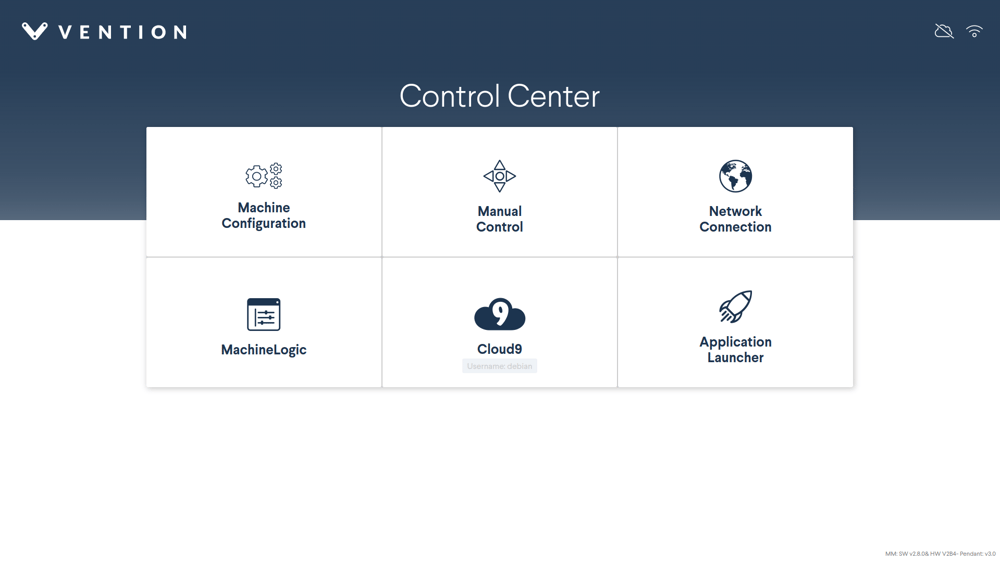
Software Included
MachineMotion 2 comes with pre-loaded control and machine operations software – all of which is accessible through the MachineMotion Pendant or via computer with an Ethernet connection.
Control Center
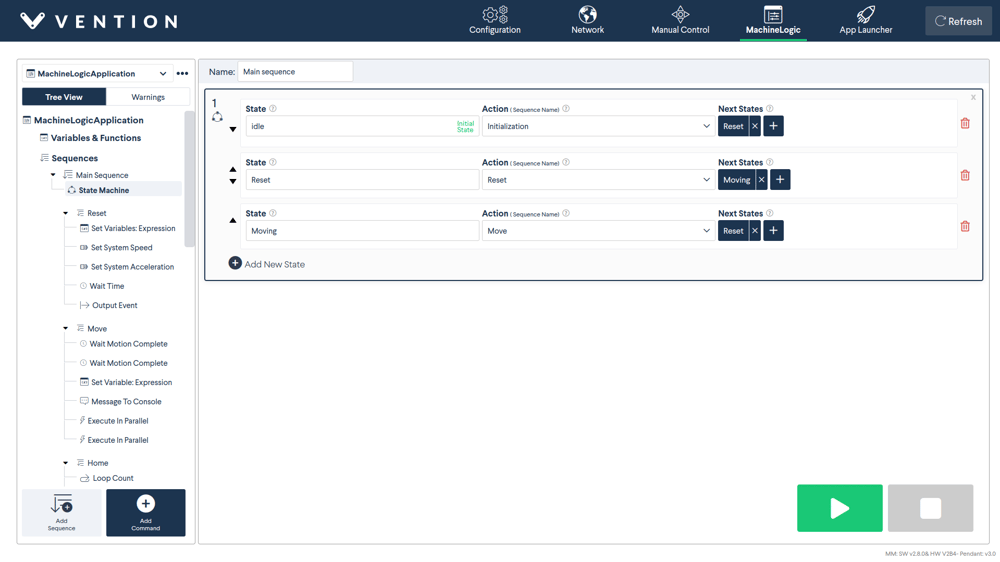
MachineLogic
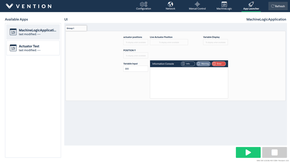
Application Launcher
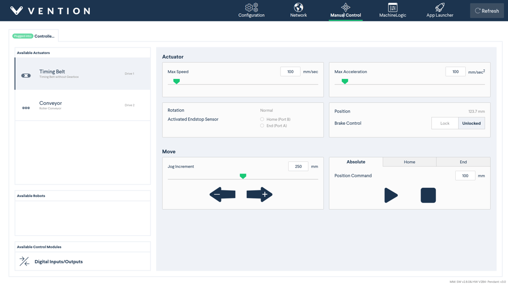
Manual Mode
Technical Specifications
Mechanical Specifications
| Item | Specification |
|---|---|
| Shock resistance | Enclosure validated as per IEC-60068-2-31 |
| Ingress protection | IP40 |
| Mounting |
|
Electrical Specifications
| Item | Specification |
|---|---|
| Processor | Intel® Core™ i3-N300 Processor 0.8 GHz (6MB Cache, up to 3.8 GHz, 8 cores, 8 Threads) |
| Graphics Display | 13.3-inch, FHD (1920 x 1080) OLED 16:9 aspect ratio, 0.2ms response time, 60Hz refresh rate, 550nits HDR peak brightness, 100% DCI-P3 color gamut, 1,000,000:1, VESA CERTIFIED Display HDR True Black 500, 1.07 billion colors, PANTONE Validated, Glossy display, 70% less harmful blue light, TÜV Rheinland-certified, SGS Eye Care Display, Touch screen |
| Memory | 8GB LPDDR5 on board |
| Storage | 256G UFS 2.1 |
| Front and rear facing cameras |
|
| Audio |
|
| Network and Communication | Wi-Fi 6(802.11ax) (Dual band) 2*2 |
| Ethernet Switch | 3 ports 10/100MB |
| Battery | 50WHrs, 2S1P, 2-cell Li-ion |
| Power Consumption |
|
| Nominal Input Voltage | 24V |
| Input Voltage range | 23.5V-25V |
| Safety Cable length connected to Safety OUT | Up to 50m |
| Emergency Stop Button | 2x NC Dry contact channels |
| Connectors |
|
| Hardware Compatibility |
|
Pin Out
Safety IN – M12A-12 pins Female
| Pin | Description |
|---|---|
| 1 | 24V |
| 2 | 0V |
| 3 | MachineMotion Safety Channel 1 Contact 1 |
| 4 | MachineMotion Safety Channel 1 Contact 2 |
| 5 | MachineMotion Safety Channel 2 Contact 1 |
| 6 | MachineMotion Safety Channel 2 Contact 2 |
| 7 | Reset Contact 1 |
| 8 | Reset Contact 2 |
| 9 | Safety IN Ethernet TX+ |
| 10 | Safety IN Ethernet TX- |
| 11 | Safety IN Ethernet RX+ |
| 12 | Safety IN Ethernet RX- |
Safety OUT – M12A-12 pins Male
| Pin | Description |
|---|---|
| 1 | 24V |
| 2 | 0V |
| 3 | MachineMotion Safety Channel 1 Contact 1 |
| 4 | MachineMotion Safety Channel 1 Contact 2 |
| 5 | MachineMotion Safety Channel 2 Contact 1 |
| 6 | MachineMotion Safety Channel 2 Contact 2 |
| 7 | Reset Contact 1 |
| 8 | Reset Contact 2 |
| 9 | Safety OUT Ethernet TX+ |
| 10 | Safety OUT Ethernet TX- |
| 11 | Safety OUT Ethernet RX+ |
| 12 | Safety OUT Ethernet RX- |
Mechanical Specifications
| Item | Specification |
|---|---|
| Shock resistance | Enclosure validated as per IEC-60068-2-31 |
| Ingress protection | IP40 |
| Mounting |
|
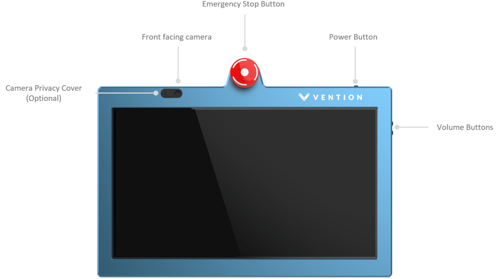
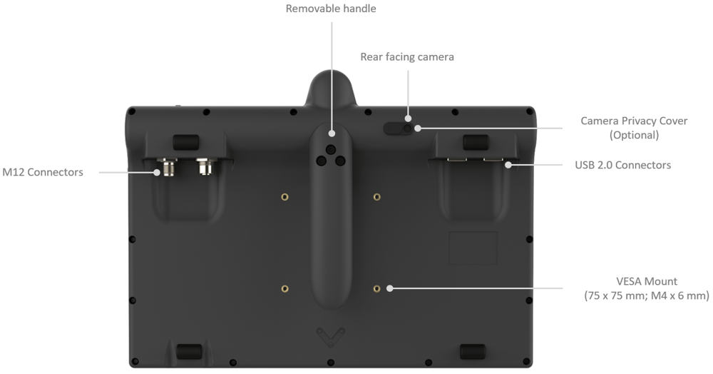
Physical Interface
Power Button Functionality
- Pressing once on the power button while the Pendant V3 is OFF will power it ON.
- Pressing more than 10 seconds on the power button while the Pendant is ON will power it OFF.
- The Pendant goes into low brightness mode after 30 minutes of no interaction. Pressing once on the power button while the Pendant is ON and in low brightness mode will change the display to full brightness.
- If the Pendant is not connected to a MachineMotion controller, it will power OFF after 10 minutes.
- The Pendant V3 includes 2 optional camera privacy covers (as shown in Figures 6 & 7) which can be installed by the user if required.
Safety Data
The pendant V3 displays an emergency stop button which is connected to the safety loop of a MachineMotion v2.
When evaluating the performance of a safety function utilizing the pendant V3 attention shall be made in regards to the number of daisy chained emergency stop buttons and interlock devices. Fault masking reduces the performance level of the safety function. Guidance on fault masking can be found in ISO/TR 24119.
Safety data can be found in the following table depending on if the Pendant V3 is daisy chained or not.
| Function | PL | Cat. | MTTFd | DCavg |
|---|---|---|---|---|
| Pendant V3 - Daisy Chained | d | 3 | 697 | 60.01% |
| Pendant V3 Single unit | e | 3 | 698 | 97.72% |
The above information have been calculated based on the following operation conditions :
| Data | Value | Unit |
|---|---|---|
| dop | 365 | days/years |
| hop | 24 | hours/days |
| tcycle | 8640 | s/cycle |
EU Declaration of Conformity
The Pendant V3 is in compliance with the Machinery directive, the RoHS directive and the RED. The EU declaration of conformity is available in the documentation section of the product details page of the Pendant V3.