Enclosed Ball Screw Actuator
Overview
The enclosed ball screw is a rigid, high-force actuator for the toughest applications. Thanks to its pinch point-free configuration and fully sealed body, you can deploy it in dusty environments where other actuators can’t keep up.
The actuator is guided by four robust linear profile bearings and two guiding rails for maximum rigidity. It comes in five lengths, ranging from 360 mm to 2295 mm.
Composition
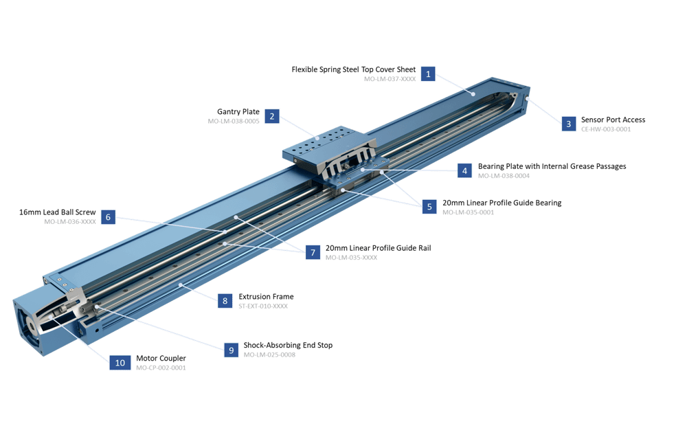
- A thin spring-steel cover seals off the top of the enclosed ball screw actuator, keeping contaminants out and eliminating pinch points. The cover is held down by magnetic strips mounted in the extrusion body.
Note: Cover is not load bearing. Do not apply a load to it, or it will break. - The 225 mm gantry plate offers 32 holes for mounting components, as well as an easy-access grease point that lubricates all moving components in the actuator at the same time.
- Sensor port access for home and end of travel detection. The ports come with pre-installed plugs.
- The bearing plate connects four linear profile guide bearings together and attaches them to the gantry plate. It also features grease passages that evenly distribute lubricant to all components.
- 20 mm linear profile guide bearings provide excellent strength and rigidity.
- The 16 mm lead ball screw provides extremely accurate, rigid, and high-force actuation for extreme applications.
- 20 mm linear profile guide rails locate the linear ball bearings. Two rails are installed in each actuator for maximum rigidity in all directions.
- A specially designed extrusion profile provides the outer structure, as well as mounting points for other components. The frame is 135 mm wide and 90 mm tall.
- Shock absorbing end-stops are pre-installed on the actuator; there is no need for external bump stops.
- The motor is connected to a zero-backlash coupling for efficient and accurate power transmission.
Application
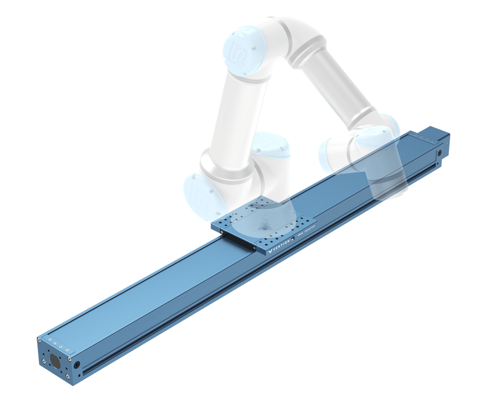
The enclosed ball screw is an extremely rigid actuator, both stronger and smaller than Vention’s previous ball screw. The actuator can be used in horizontal and vertical configurations. Mount it in any direction to suit your needs; it’s flexible enough for a wide range of applications.
One great use for the enclosed ball screw actuator is as a heavy payload range extender. The enclosed ball screw can fully support large cobots, like the Doosan H2515 and H2017, on its own.
The enclosed ball screw can also be used as a vertical range extender, thanks to its low back drivability and high actuation force. Additionally, the enclosed ball screw can support vertical range extender applications.

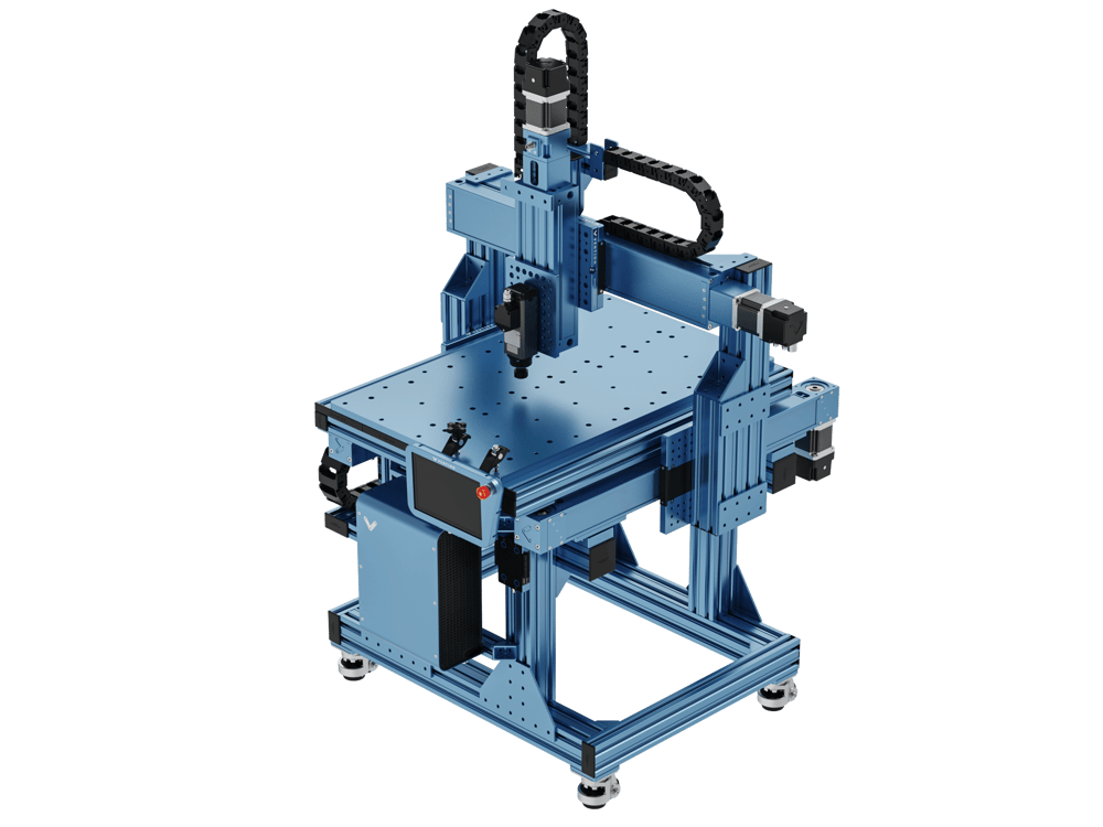
The enclosed ball screw is ideal for highly rigid applications like CNC routing. By using the enclosed ball screw for the Y and Z axes, you can design CNC routers that can easily cut wood, plastic, and soft metals (like aluminum).
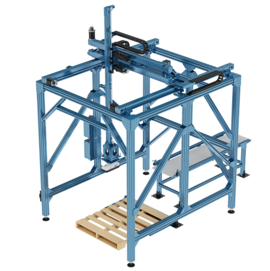
Finally, the enclosed ball screw actuator is ideal for the Z axis in heavy-load palletizers.
Explore public designs to get ideas on how you could use the enclosed ball screw actuator.
Technical Specifications
| Displacement ratio | 16 |
| Force per unit of input torque (N / Nm) | 392.7 |
| Maximum input torque (Nm) | 12 |
| Accuracy | 0.05 mm per 300 mm of length |
| Repeatability including backlash (mm) | ±0.025 |
| Total Backlash (mm) | 0.01 |
| Backdrive resistance | High |
| Max lifting capacity | 300 kg |
| Motor compatibility | NEMA 34, 14-mm shaft with 5-mm key |
| Sensor compatibility | Vention’s Flush Inductive Proximity Sensor (CE-SN-004-0003) only |
Available Sizes
The enclosed ball screw actuator comes in five lengths (length refers to extrusion body length).
To calculate actuator travel for the single gantry version, subtract 215 mm from the body length. (e.g.: 1530 - 215 = 1315 mm)
The dual gantry configuration utilizes two 223 x 223 mm gantry plates, which can be placed flush with one another or spaced according to the design requirements. To calculate actuator travel for the dual gantry version, subtract 438 mm from the body length. (e.g.: 1530 - 438 = 1092 mm)
Single Gantry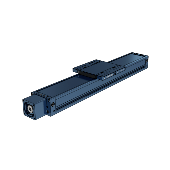
|
Dual Gantry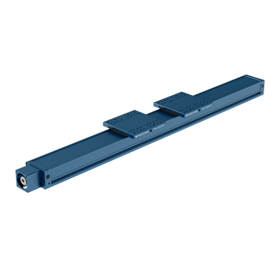
|
|
| Part Number | MO-LM-039-XXXX | MO-LM-052-XXXX |
| 360 mm | 11.97 kg | - |
| 585 mm | 14.81 kg | - |
| 855 mm | 18.30 kg | - |
| 1530 mm | 27.07 kg | 31.80 kg |
| 2295 mm | 36.98 kg | 40.70 kg |
Load Capacity
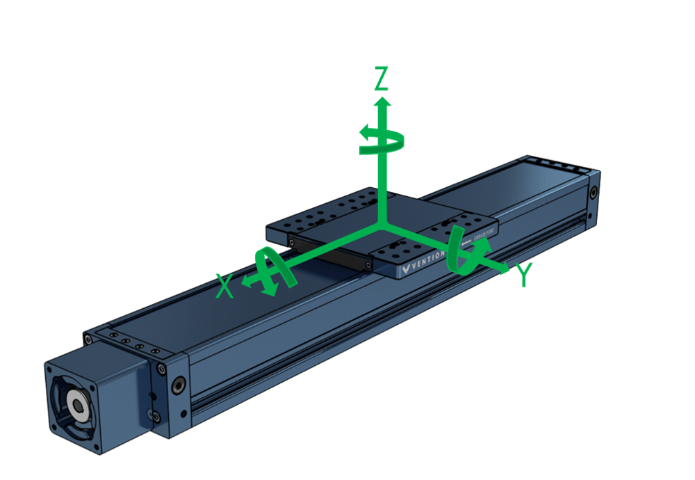
The table and figure below describe the nominal and maximum loads and moments in each direction. The values are the same for both single and dual gantry versions, the later offering users the ability to better distribute the load across both gantry plates.
| MO-LM-039-XXXX | MO-LM-052-XXXX | |
|---|---|---|
| Nominal axial force (Fx) | See driving forces | See driving forces |
| Max peak axial force (Fx) | 3250 N | 3250 N |
| Nominal roll moment (Mx) | 935 Nm | 1500 Nm |
| Max peak roll moment (Mx)* | 2000 Nm | 2000 Nm |
| Nominal horizontal force (Fy)** | 5000 N | 5000 N |
| Max peak horizontal force (Fy)** | 10 000 N | 10 000 N |
| Nominal pitch moment (My) | 1630 Nm | 2000 Nm |
| Max peak pitch moment (My)* | 2500 Nm | 2500 Nm |
| Nominal vertical force (Fz)** | 5000 N | 5000 N |
| Max peak vertical force (Fz)** | 10 000 N | 10 000 N |
| Nominal yaw moment (Mz) | 1630 Nm | 2000 Nm |
| Max peak yaw moment (Mz)* | 2500 Nm | 2500 Nm |
*Note that max peak values represent the absolute maximum load. Peak loads are acceptable during one-time events such as emergency stops, but operating at peak loads continuously will cause excessive wear and shorten the actuator’s lifespan.
**Note that force limitations depend on the supporting structure and the unsupported length of the actuator. Listed values are for unsupported lengths of 855 mm or less.
Driving Force
The driving force indicates how much weight the actuator can move and how quickly it can accelerate. This force is shown as “Fx” in the Load Capacity figure.
For a more in-depth explanation of driving force, see the “calculating actuator forces” section of our linear actuator selection guide, or ask a Vention Application Engineer for help.
Note: During MachineMotion’s boot up sequence, the holding force is momentarily 65% of its rated value. Please keep in mind when using in vertical and/or angled applications.
Buckling and Critical Speed
In terms of load and speed, ball screws are limited in two ways beyond normal material and bearing strength.
First, when dealing with ball screws, you must consider buckling. Buckling is when a long structure (in this case, the screw) suddenly bows and deforms due to compressive load. This deformation makes the screw even less rigid and will usually lead to screw failure. Since buckling is a critical failure mode of ball screws, it is important to consider it and the loads applied to ensure it will not occur.
The buckling condition is defined as:
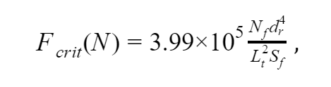
where:
Nf is the fixation coefficient. For the enclosed ball screw, this is 1.0, since it is designed with a fixed-fixed screw fixation.
dr is the root diameter of the ball screw, which in our case is 12.969 mm.
Lt is the distance between supports. This is the distance between two fixed points on the ball screw at any given point. The largest value will be the distance between a shaft support and the ball nut.
Sf is the safety factor. Because buckling is such an important consideration, we use a safety factor of at least 1.5.
| Part Number | Max Distance Between Supports (mm) |
|---|---|
| MO-LM-039-0360 | 248 |
| MO-LM-039-0585 | 473 |
| MO-LM-039-0855 | 743 |
| MO-LM-039-1530 | 1418 |
| MO-LM-039-2295 | 2183 |
Using the above values and info, the permissible buckling loads are:
| Part Number | Max Permissible Compressive Load (N) |
|---|---|
| MO-LM-039-0360 | 122 350.8 |
| MO-LM-039-0585 | 33 634.8 |
| MO-LM-039-0855 | 13 631.2 |
| MO-LM-039-1530 | 3742.5 |
| MO-LM-039-2295 | 1579.1 |
Because the actuator’s max driving force is 3,250 N, the only length where buckling becomes a limitation is on the 2,295 mm model (MO-LM-039-2295). When using this length, make sure the driving forces do not exceed 1579.1 N.
Second, you must consider the shaft’s critical speed. This is the rotational speed at which the screw will begin to violently vibrate. This behavior is due to the screw’s harmonics, and it can damage the ball screw.
Critical Speed is defined as:
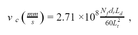
where Ld is the screw lead. In our case, the lead is 16 mm.
Since we’ve already defined all the other parameters, we can jump into the calculations.
| Part Number | Max Linear Speed (mm/s) |
|---|---|
| MO-LM-039-0360 | 15 238*** |
| MO-LM-039-0585 | 4189*** |
| MO-LM-039-0855 | 1698*** |
| MO-LM-039-1530 | 466*** |
| MO-LM-039-2295 | 197 |
***Note: The max travel speed of a ball screw is limited to 200mm/s by default to avoid overspeed issues. If you have a screw shorter than the 2295mm and want to increase speed, you may configure your actuator as a “custom” type to bypass this safety limit.
For both MO-LM-039-1530 and MO-LM-039-2295, the max motor speed is greater than the max ball screw speed. Therefore, you must be careful not to exceed the max linear speed values given above while programming and operating.
Assembly Instructions
The enclosed ball screw actuator comes completely assembled. All you need to do is install your choice of powertrain components, such as a motor and brake, and add sensors.
Notes:
- When installing motors, apply a small amount of grease to the motor shaft so that it is lightly coated. This will reduce the possibility of fretting corrosion occurring during operation, making future removal easier.
- Moreover, do not use excessive force (hammering, prying or using screws to “push” the motor) to install the motor.
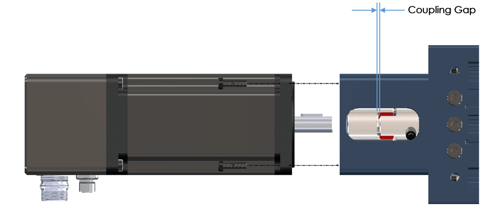
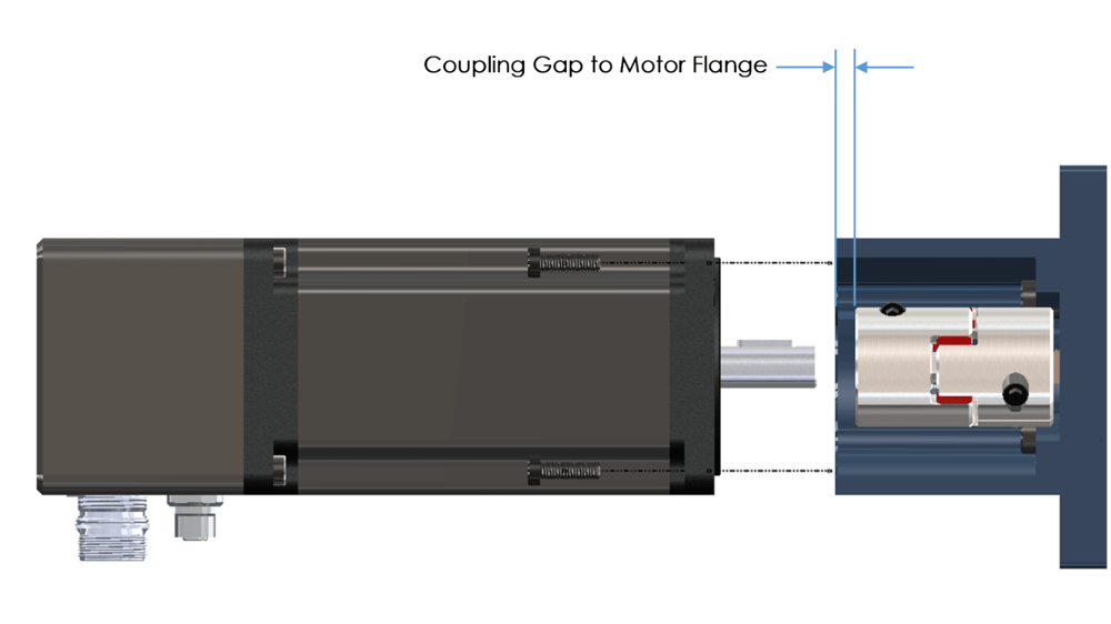
i) To attach the powertrain components, push the shaft into the motor coupling. The coupling is pre-installed on the actuator.
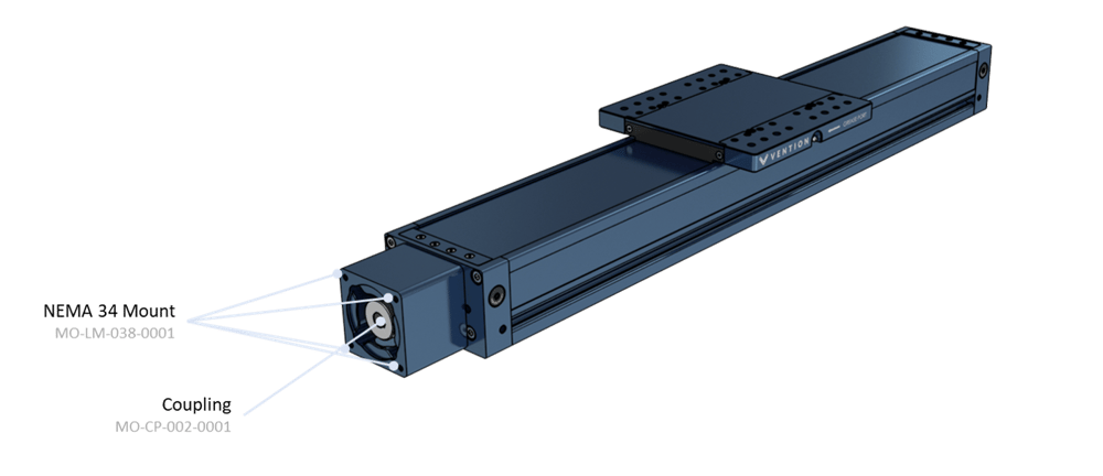
ii) Check the gaps between the coupling and the motor as shown in the following images. The coupling gap should be 1-2mm. With the motor installed check that the “coupling gap to motor flange” is not touching the motor face. Failure to properly set either gap will cause damage to the motor and or coupling.
 |
 |
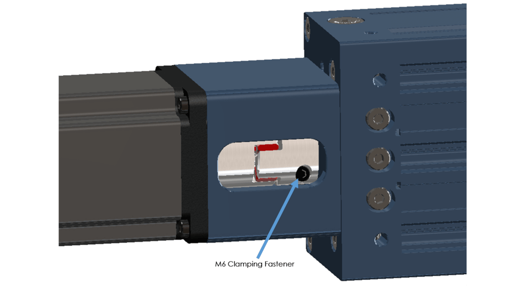
iii) After verifying the above, tighten the 4 M6 bolts that hold the motor onto the actuator, followed by the two clamping fasteners in each coupling half. During final installation, medium strength thread locker is highly recommended for the motor side clamping bolt. All M6 bolts should be torqued to 10-12Nm:
 |
 |
iv) You can install sensors in any of the four sensor port locations. To install a sensor, remove the port plug and screw the sensor all the way into the hole until it bottoms out. Unscrew the sensor by a half turn to ensure it is not compressing the bump stop. Install one jam nut and tighten it to lock the sensor in place.
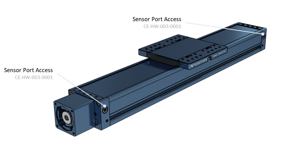
Note: Sensor ports are available on both sides of the actuator. The only sensor compatible with the actuator is the flush mount proximity sensor (CE-SN-004-0003).
v) Once the powertrain and sensors are in place, attach the actuator to your structure. Connect the actuator’s extrusion body or end plates to any appropriate structural component. To ensure sufficient rigidity, maintain a minimum support distance of 855 mm.
vi) Optional: Route cables through a drag chain. Drag chain can be installed on the gantry plate’s underside, as shown below. If you use the included M8 x 8-mm fasteners to attach the drag chain to the gantry, you can thread into the same hole from the bottom even if something is attached from the top of the gantry, expanding your drag chain installation options.
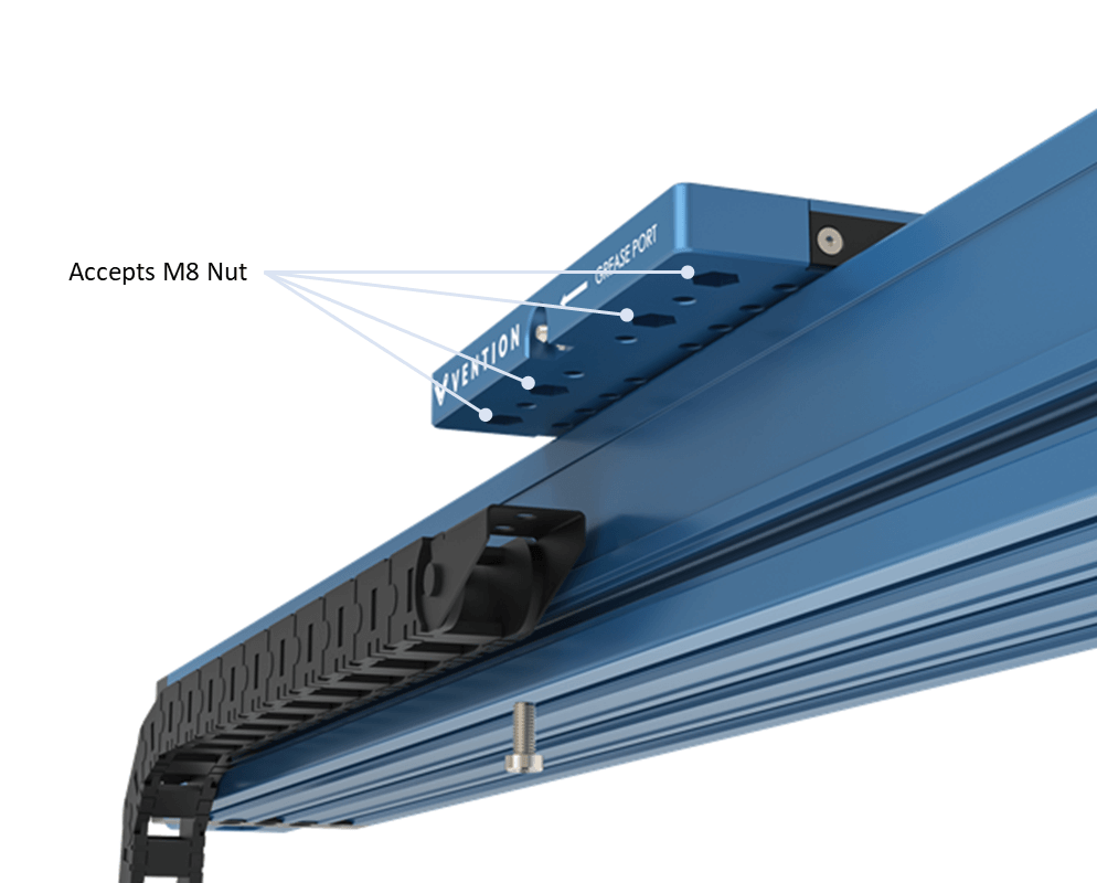
vii) Mount parts to the gantry using the threaded holes, counterbored holes or by installing nuts in the counterbored holes. The included M8 nuts easily transform the counterbored holes into threaded holes for maximum flexibility.
Note: When mounting multiple enclosed actuators in parallel, refer to the Self-Aligning Mount Technical Document.
Maintenance
For maintenance instructions, please see the appropriate section in our Maintenance Technical Document.de-39)