Material Handling
Overview
This material handling technical document covers aspect of any devices used in the transportation of boxes, packages or parts.
Ball Transfers
Vention’s ball transfers are threaded for tool-less installation into extrusion or tooling plates.
![]()
Ball Transfer Summary
- Installed height is 26mm from the mounting surface to the top of the ball.
- Ball transfers have M8 thread for attachment into extrusion via t-nut or directly into threaded holes in tooling plates.
- Dynamic load capacity is 50 kg per unit.
- Typically arranged in “beds” at the start or end of conveyors to allow packages to be rotated.
- Spacing is dependant on the weight and size of the package, however typical intervals are between 90-135mm.
- When attached to extrusions, a few extrusions can be placed side by side to get the correct spacing.
- Vention’s ball transfer should only be used vertically, with the ball side facing upwards.
- They cannot be used with light duty extrusion.
Flow Rail
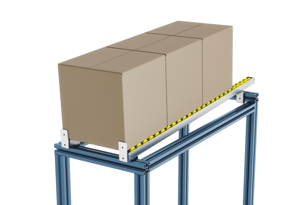
Vention’s flow rails let you design smart material storage racks. When you mount the flow rails at a slight angle, gravity will cause items to slide forward automatically.
You can also mount flow rails without any angle; built-in flanges prevent packages from falling off the sides. Mounting brackets feature an end stop and allow for flow rail angles of ±6 degrees.
Flow Rail Technical Specifications
| Load capacity | 25 kg / meter |
| Mounting inclination | +/- 10 Degrees |
| Maximum unsupported distance | 1530 |
Assembling Flow Rails
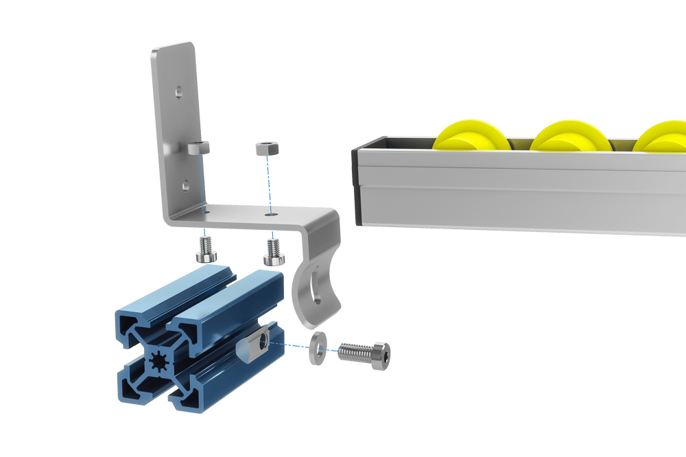
Mounting flow rails to a Vention assembly is as easy as installing the flow rail (part number MO-CV-011-XXXX) on the mounting bracket (MO-CV-011-0001), then attaching this assembly to your extrusion.
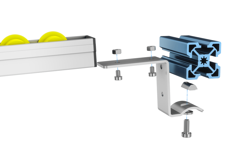
There are two mounting options for the brackets: 1. With an end stop, which prevents boxes from falling off the end of the rail. This mounting option must be placed at the end of the flow rail (see figure). 2. Without an end stop, which does not prevent items from falling off. This mount can be placed anywhere along the rail (see figure). Both cases use the same mounting bracket (MO-CV-011-0001).
To install a mount:
- Attach the flow rail to the bracket.
- For each bracket, slide two M6 hex nuts (HW-FN-033-0003) into the corresponding slot on the flow rail. You may need to apply some pressure to fit the nut through the black plastic cap on the flow rail.
- Attach each bracket to the flow rail with two M6 x 8-mm bolts (HW-FN-005-0008), using the nuts positioned from the previous step.
- Torque to no more than 4Nm.
- Attach the assembly to the extrusion.
- Position your t-nut in the extrusion, then attach the mounting bracket to the extrusion with one M8 x 16-mm screw (HW-FN-003-0016) and one steel/rubber washer (HW-WS-001-0005).
- Torque the M8 bolt to no more than 10Nm.
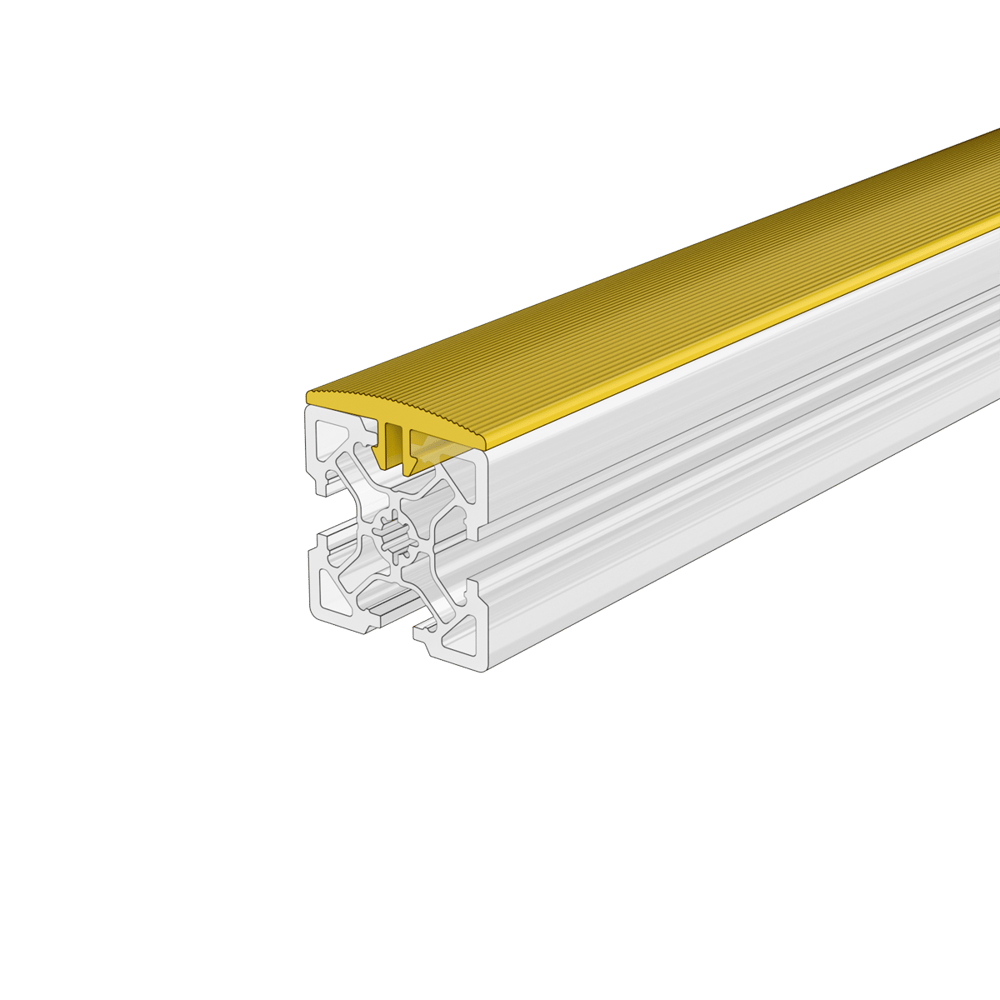
Wear and Protection Strips
Vention’s plastic wear and protection strips clip into extrusion t-slots. They are available in two colours grey (ST-PN-012-2295__2) and yellow (ST-PN-013-2295__2). Strips are used to protect both aluminum extrusion and any parts that come into contact with it. Typical uses include conveyor guides and racking systems. Strips are shipped in lengths of 2295mm and require cutting before installation.
Strip Installation
- Measure length of strip required and mark.
- Cut strip to length. Cutting strips is easily done with snips, however it can also be accomplished with a saw or utility knife.
- Install strip by pushing into extrusion slot, a soft blow hammer is required to fully seat the stip into the extrusion.
Strip Removal
- Using a pry bar, lift a corner of the strip off the extrusion.
- Continue to peel the strip off.
- Strip can be reused after removal.
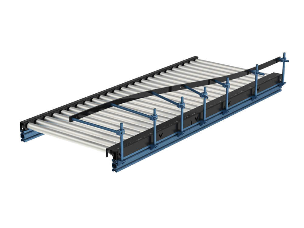
Flexible Conveyor Guide
Vention’s flexible conveyor guide offers a new, simple, and cost-effective way to index, direct, or funnel boxes along a conveyor during material handling operations such as down-the-line collection by a Vention palletizer. This new guiding solution makes use of some of Vention’s well-known components such as our Round Extrusion (ST-EXT-008-XXXX) and our Die Cast Gussets (ST-GP-003-0001). With the addition of the new Round Extrusion Clamping Adaptors (ST-GP-004-0007) and Flexible Conveyor Guide Strips (ST-PN-020-2295) a fully height and stroke adjustable, flexible box guide can be created. It can support complex curves with bending radii as tight as 500 mm.
Design Tips
- Ensure you have sized your round extrusion lengths in MachineBuilder for stroke adjustment (conveyor width) to consider all box sizes if multiple Stock Keeping Units (SKUs) will be processed.
- Ensure you have also sized your round extrusion lengths in MachineBuilder for height adjustment to consider the tallest box if multiple SKUs will be processed. The conveyor guide should be placed mid-box height.
- The average hole spacing on the conveyor guide is 405mm. If you are guiding a straight path, not all holes need to be supported. It is recommended to use all holes to support complex curves.
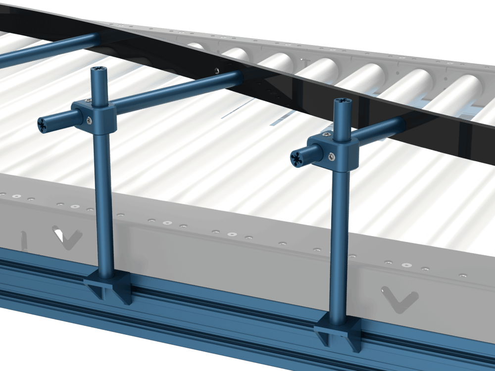
Assembling the Flexible Conveyor Guide
The following instructions are suited for one possible extrusion frame mounting configurations.
- Tap one side of every round extrusion. A threaded hole will be required either to attach the vertical round extrusion to the mounting gusset, or to attach the guiding strip to the end of the horizontal round extrusion.
- Install your GP gussets on to your supporting extrusion frame with the horizontal surface facing up, and roughly spaced 405mm from one another. The gussets do not need to be fully secured at this stage.
- Fasten the round extrusion to the gusset.
- Install the round extrusion clamping adaptor on all the vertical round extrusions and lock it in place with the set screw. Ensure they are all oriented the same way and flush with the top surface of the extrusion, this will ease installation.
- Slide the horizontal extrusion into the clamping adaptor with the threaded side facing toward the conveyor. Loosely secure all horizontal extrusions with the same amount of stroke to ease with installing the flexible guiding strip.
- Fasten the strip using the provided flat head screws starting from one end. Skip the left- and right-most holes if you need to link multiple guide strips together, use a 1x2 Assembly Plate (ST-GP-001-0016) to link multiple strips. You may use one of the center double holes if needed, this feature was included for cases where the strip may need to be cut in half.
- Adjust the height, stroke and rotation of the round extrusion clamp as needed. Secure all fasteners and gussets.