Linear Guides & Accessories
Contents
Introduction
Allow your project to freely and effortlessly move along Vention extrusions using Vention rollers, linear bearings and shafts powered by Nippon Bearings and PBC Linear, or our heavy duty Enclosed Linear Profile Guides.
This datasheet provides technical specifications for Vention’s Linear Guides and Accessories V2. For details on Vention’s Linear Guides and Accessories V1, refer to the ‘Documentation for Previous Product Versions’ section at the bottom of this page.
Note: Vention rollers, linear bearings and shafts, and enclosed linear profile guide are not designed to work in conjunction. Your Vention system must feature either Vention rollers, linear bearings and shafts, or the enclosed linear profile guide not a combination of them.
Linear Bearing and Shaft Overview
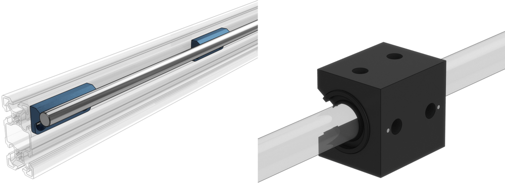
Vention’s linear bearing system features a 16-mm linear shaft and linear bearings to glide along Vention extrusions. The shaft comes in four lengths and is compatible with two types of linear bearings:
- Linear ball bearings (MO-LM-010-0001), which use recirculating balls.
- Plain sliding bearings (MO-LM-010-0010 and MO-LM-010-0012), which do not contain any moving parts or rolling elements.
Plain bearings are available in precision fit and compensated fit versions:
- Precision fit bearings (MO-LM-010-0010) have the tightest inner diameter (ID) running clearance and are identified with a P engraved on top of the housing.
- Compensated fit bearings (MO-LM-010-0012) have additional ID clearance and are identified with a C engraved on top of the housing.
In parallel shaft applications, one rail’s bearings should all be precision fit, and the opposite rail’s bearings should all be compensated fit.
Note: Please refer to the maintenance instructions before commissioning any linear bearing.
Technical Specifications
Linear Shaft Technical Specifications
| Available Lengths | 585 mm, 855 mm, 1530 mm, 2295 mm |
| Material | Solid carbon steel hardened to 60HRC |
Linear Bearings Technical Specifications
| Linear Bearing Type | Linear ball bearing (MO-LM-010-0001) | Plain bearing (MO-LM-010-0010 and MO-LM-010-0012) |
| Maintenance | Lubrication and maintenance required | Maintenance-free with optional lubrication for better performance |
| Environment | Moderate temperature, dry, and low-dust | Extreme (wet, low or high temperature, vibration, dust, or contamination) |
| Coefficient of friction | 0.05 | 0.3 |
| Load rating | Up to 1500 N per bearing* | Up to 10,000 N per bearing* |
| Maximum linear speed | 3 m/s | Up to 1.5 m/s** |
| Moment load | High: moment arm distance(D)/bearing distance(L) up to 10 | Limited: moment arm distance(D)/bearing distance(L) must be under 2 |
| Operational life | Long, if properly maintained and operated as specified | Limited, when the wear limit is reached, the bearing must be replaced |
| Break-in period | No break-in period | Approximately 50 - 100 full cycles needed to complete the break-in period |
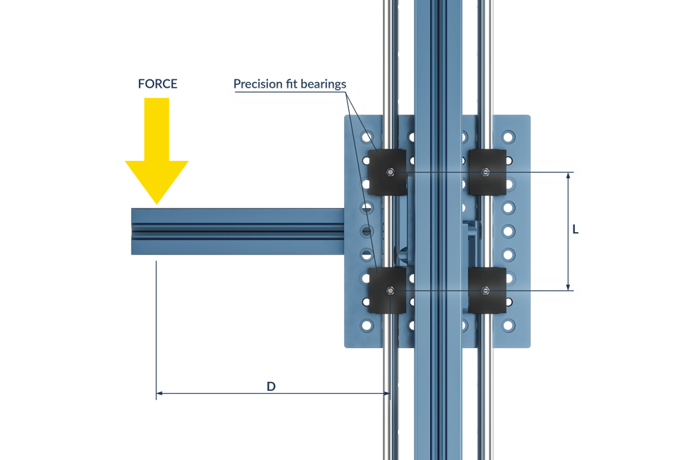
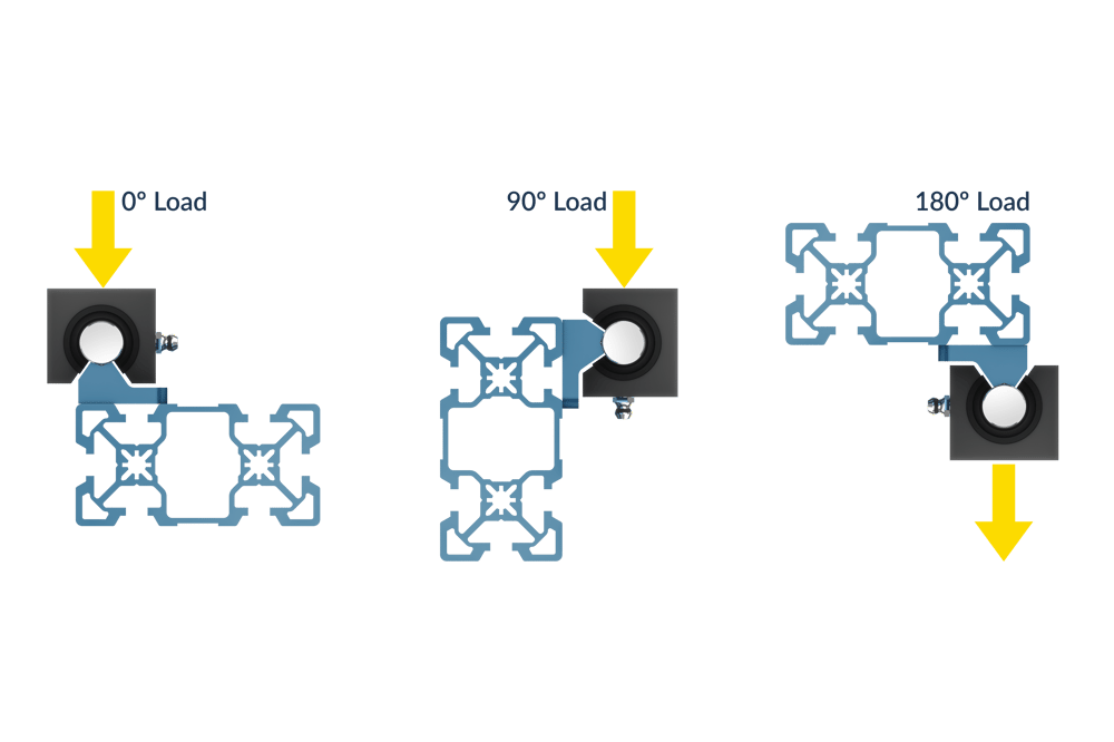
*Bearing load rating and orientation
Both the plain and linear ball bearings can operate in any orientation, but their load rating varies depending on the orientation.
Static Load Rating
| Linear Bearing Type | 0° load rating (N) | 90° load rating (N) | 180° load rating (N) |
| Linear ball bearing (MO-LM-010-0001) | 1550 | 1085 | 620 |
| Plain bearing (MO-LM-010-0010 and MO-LM-010-0012) | 10080 | 6940 | 2770 |
Dynamic Load Rating
| Linear Bearing Type | 0° load rating (N) | 90° load rating (N) | 180° load rating (N) |
| Linear ball bearing (MO-LM-010-0001) | 1250 | 1000 | 600 |
| Plain bearing (MO-LM-010-0010 and MO-LM-010-0012) | Up to 10080*** | Up to 6940*** | Up to 2770*** |
**Maximum speed (m/s) = 407.77 / Dynamic Load (N).
***Maximum Dynamic Load (N) = 407.77 / Speed (m/s).
Assembly Instructions
- Vention linear shafts come with mounting blocks pre-installed. The mounting blocks have HP features to ensure proper alignment.
- Install the shaft to the corresponding extrusion frame using the provided M8 countersink fasteners and T-nuts.
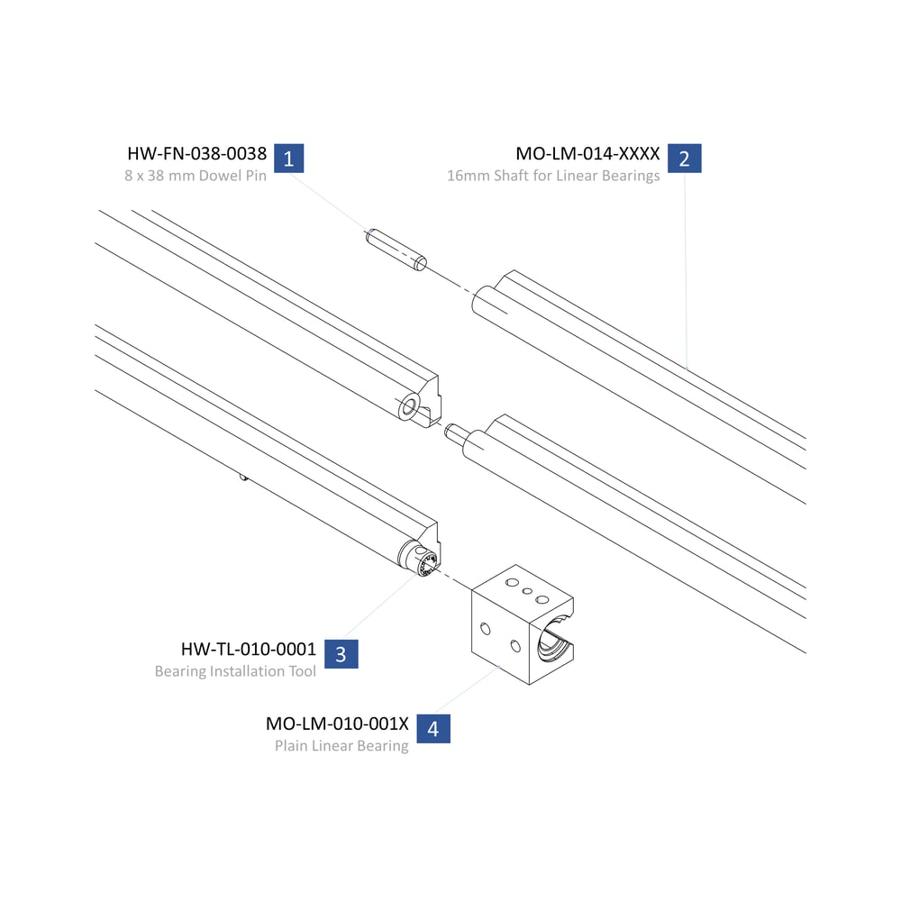
- If multiple shafts are to be butt joined, use the included 8mm pin.
- First tap the pin (1) into the end of the shaft with a soft hammer. Pin should protrude ~20mm out of the shaft (2).
- Install second shaft (2) onto the extrusion with M8 fasteners, leaving them loose so that the shaft can slide along the extrusion.
- Push second shaft onto pin of first, light taps with a soft blow hammer will be required.
- Finally, attach the bearings to associated gantry or actuator using the M8x12mm fasteners provided.
NOTE: An important consideration when planning your butt-jointed rail system is where the joints are located. Much like brickwork, it is important that rail joints do not align with each other or with extrusion joints. All joints should be offset to have optimal alignment and rigidity of the guiding system.

Bearing Instructions
When installing ball bearings (MO-LM-010-0001), it is very important to leave the plastic sleeve insert inside the bearing. This sleeve will be pushed out automatically when the bearing is pushed onto the end of the shaft. Never remove bearings from a shaft after installation. This can lead to ball bearing elements falling out of the encasing and bearing failure.
When installing plain bearings (MO-LM-010-0010 or MO-LM-010-0012), a bearing installation tool (item 3 above) is included (HW-TL-010-0001). Place the tool into the end of the shaft before installation. Failure to do so can cause damage to the plain bearings.
20mm Profile Guide Rails
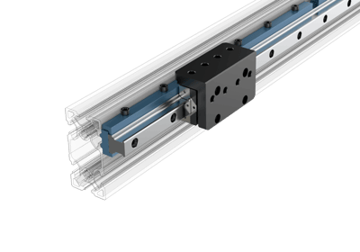
The details of this product are significant and justify their own document. Please refer to this technical document for details on this product.
Roller Wheel Overview
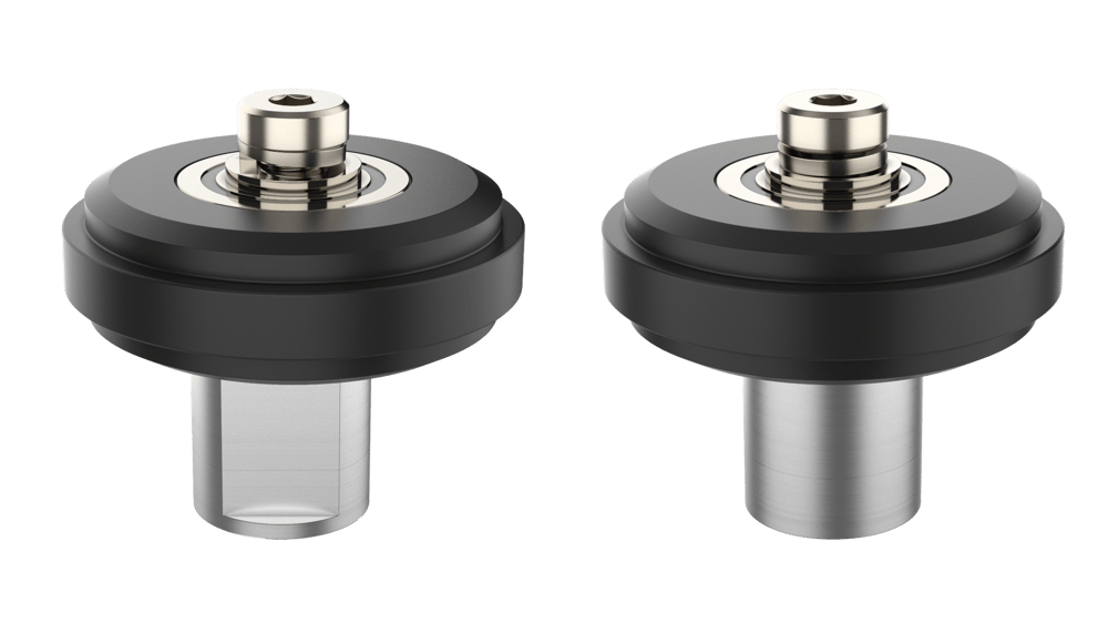
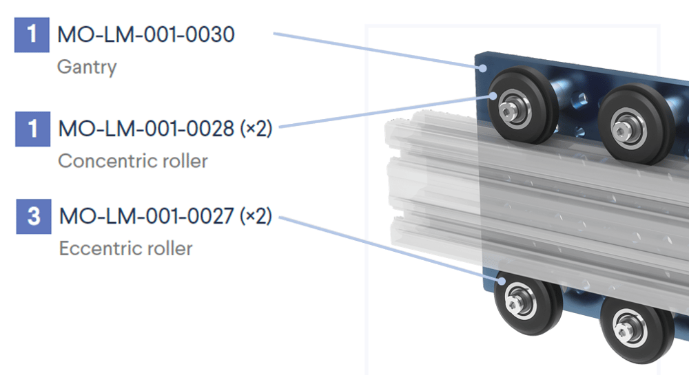
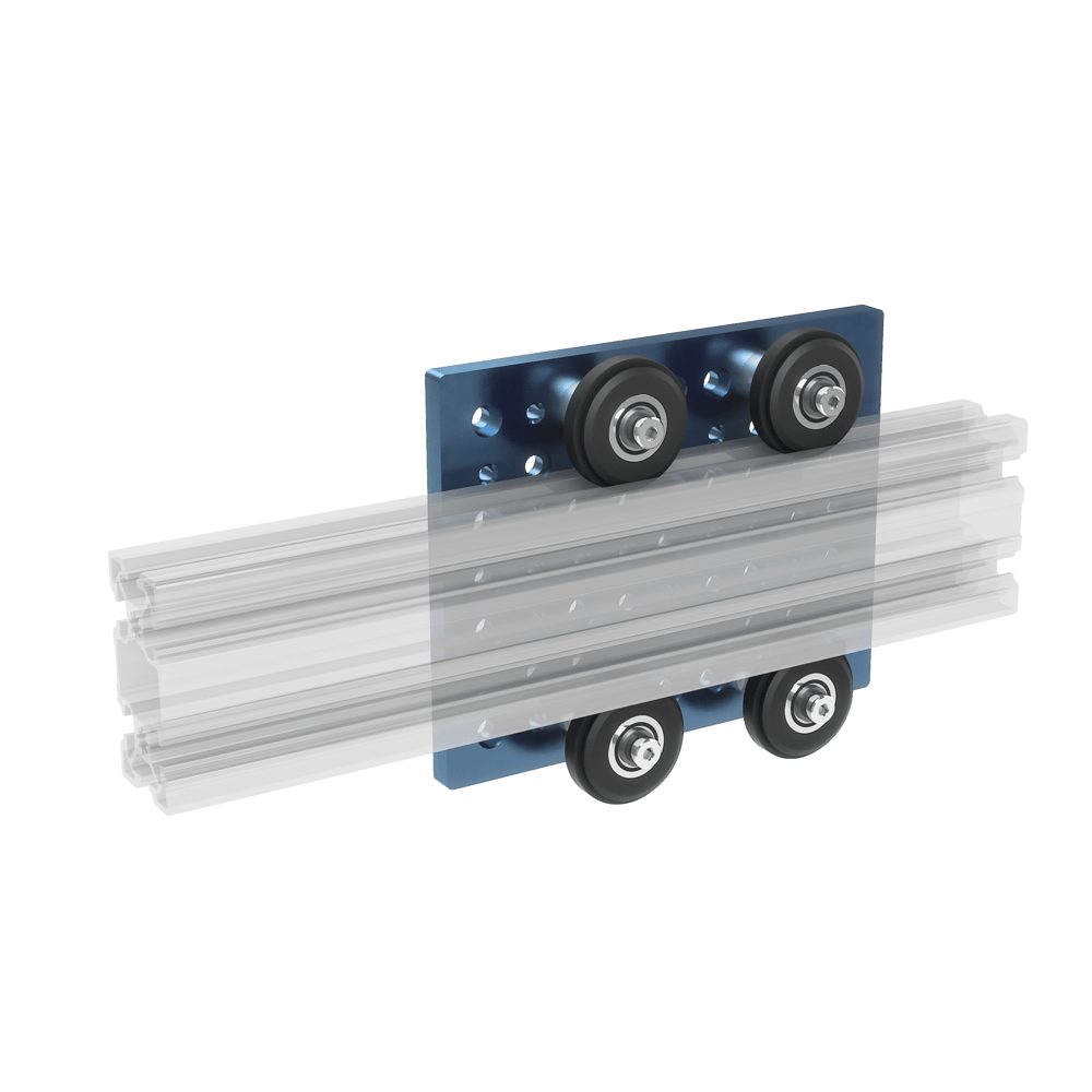
Vention features two different rollers, concentric (MO-LM-001-0028) and eccentric (MO-LM-001-0027), for all your guided applications. Consisting of a fiber glass reinforced nylon wheel and a double-sealed deep-groove ball bearing, both rollers are compatible with all of Vention’s gantries.
Technical Specifications
| Compatible Gantries |
|
| Bearing Axial Force Rating (N) | 225 |
| Bearing Radial Force Rating (N) | 225 |
| Driven Binding Ratio* | 10:1 |
| Rolling Resistance [N]** | 0.29 m +4.9 |
*Using a fully supported structure with no overhanging load
**Rolling resistance is a function of the load m in kg.
Assembly Instructions
- First, mount both concentric rollers to one side of your gantry using the shallow locating holes. You can distinguish both types of rollers as the eccentric rollers include a flat surface on their shaft.
- Place the stationary extrusion that acts as the guide up against the concentric wheels such that the rollers rest perfectly within the V-groove of the extrusion.
- Mount both eccentric rollers to the gantry on the opposite side of the concentric rollers, with the extrusion in between both sets of rollers.
- To ensure both eccentric rollers are properly located along the extrusion, loosen the mounting screws and rotate the eccentric roller shafts by hand until both wheels are unable to freely rotate along the extrusion and the extrusion is unable to move laterally. Do not use a wrench to further tighten the eccentric wheels as premature wear will occur.
- Hold the eccentric shaft’s position and tighten the screw up to 13Nm.
- To ensure proper engagement, move the gantry along the extrusion. There should be no play in the wheels and no resistance to the movement.
Enclosed Linear Profile Guide
Ideal for heavy duty applications, especially for dusty or dirty environments, Vention’s enclosed linear profile guides (MO-LM-028-XXXX) come in five lengths: 585mm, 855mm, 1530mm, 2295mm, and 3330mm. Each guide comes with bearing, gantry system, as well as built-in mounts for end of travel sensors.
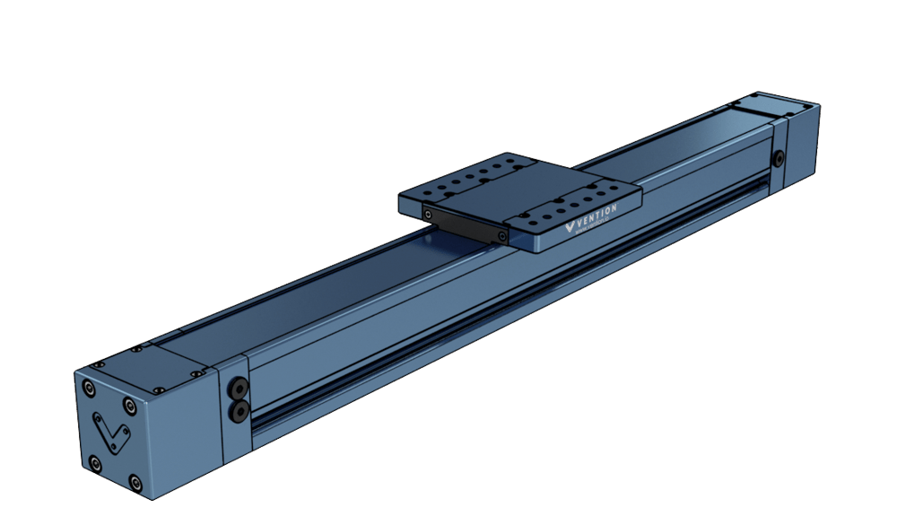
Technical Specifications
| Available Lengths | 585 mm, 855 mm, 1530 mm, 2295 mm and 3330 mm |
| Material | Steel and Aluminum |
| Vertical Load Capacity (N) | 3330 |
| Horizontal Load Capacity (N) | 3330 |
| Maximum Moment (Nm) | 500 |
Note that the enclosed linear profile guide has frictional losses due to the enclosing metal strip of 40N.
Assembly Instructions
- The enclosed linear profile bearings come fully assembled and tested. The only assembly process is installing end of travel sensors and mounting of the guide.
- To install a proximity sensor, (CE-SN-004-0003), unscrew the plug located at the sensor port of your choice using a 5mm allen key.
- Thread the sensor in until it bottoms out.
- Finally, use one of the locking nuts to fix the sensor in place by tightening down the nut on the side of enclosed guide body.
- For mounting instructions, refer to the following technical document about mounting enclosed actuators and guides in parallel here: Self Aligning Mounts
Dual Gantry Enclosed Linear Profile Guide
Ideal for heavy duty applications, especially for dusty or dirty environments, Vention’s dual gantry enclosed linear profile guides (MO-LM-041-XXXX) come in three lengths: 1530mm, 2295mm, and 3330mm. Each guide comes with two bearing-gantry systems, as well as built-in mounts for end of travel sensors.
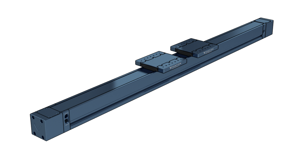
Technical Specifications
| Available Lengths | 1530 mm, 2295 mm and 3330 mm |
| Material | Steel and Aluminum |
| Vertical Load Capacity (N) | 5000 |
| Horizontal Load Capacity (N) | 5000 |
| Maximum Moment (Nm) | 750* |
Note that the dual gantry enclosed linear profile guide has frictional losses due to the enclosing metal strip of 80N.
*Note: The maximum rated moment of the dual gantry enclosed linear profile guide can be raised by increasing the spacing of the two gantry plates. To ensure the spacing is adequate for the application, please contact Vention’s application engineering team.*
Assembly Instructions
- The dual gantry enclosed linear profile bearings come fully assembled and tested. The only assembly process is installing end of travel sensors and mounting of the guide.
- To install a proximity sensor, (CE-SN-004-0003), unscrew the plug located at the sensor port of your choice using a 5mm allen key.
- Thread the sensor in until it bottoms out.
- Finally, use one of the locking nuts to fix the sensor in place by tightening down the nut on the side of enclosed guide body.
- For mounting instructions, refer to the following technical document about mounting enclosed actuators and guides in parallel here: Self Aligning Mounts
Aluminum Profile Slider
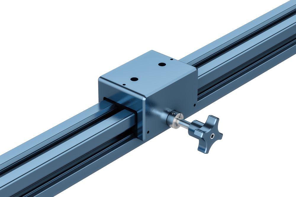
Vention’s 45mm aluminum profile slider (MO-LM-008-0002) is the best low-profile solution for building motion enabled and adjustable frames. Ideal for modular workstations and sliding doors, it slides directly onto Vention’s 45 x 45mm and 45 x 90mm aluminum extrusions. Note that the slider is not intended for high speed and high acceleration sliding applications.

Technical Specifications
| Material | Aluminum and acetal |
| Coefficient of Friction | 0.25 |
| Load Capacity (all directions) | 500 N |
| Maximum linear speed | 500 m/s |
| Maximum linear acceleration | 500 mm/s2 |
Assembly Instructions
The aluminum profile slider can be fixed to an extrusion using the counterbored holes located on the underside of the slider. You must attach the screws before sliding the assembly onto the extrusion. Check that the sliders are properly aligned before being installed on the extrusion profiles to prevent binding.
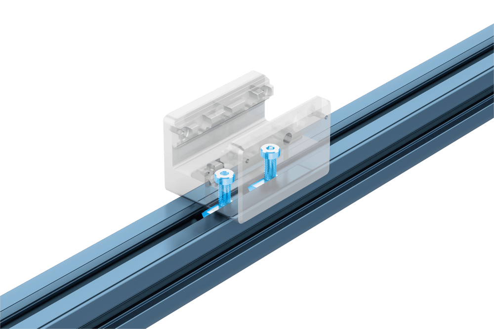
The extended-length knob produces an easily adjustable connection that is ideal for lighter loads and applications that need frequent adjustment. In either case—M8 screw (HW-FN-001-0025) or extended-length knob (HW-CP-002-0002)—you will need to install an M8 t-nut inside the extrusion t-slot. The t-nut is included in both cases.
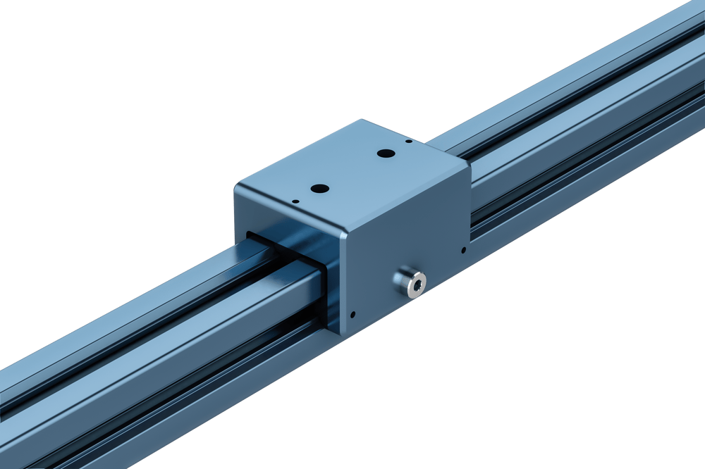
When building modular framing, you want your configuration to generate the least possible moment on the sliders to help prevent binding. The displacement force should be applied in line with the center of the slider(s), or in the center of the frame, and the static load should be centered as well.
Also, when building center-driven frames, make sure to use four or more properly aligned profile sliders to help balance any moments.
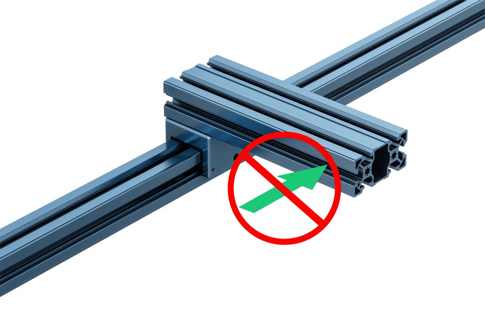
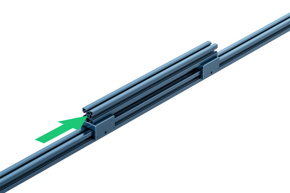
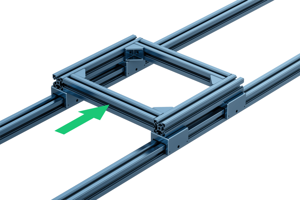
Correct slider configurations. Note that the two above driving forces do not cause a large moment seeing that they are in line with the sliders or in the center of the frame.
