Selecting a Linear Axis Actuator
Contents
Introduction
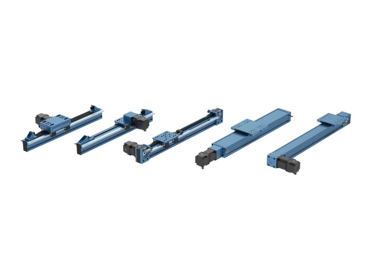
This Vention Design Tip features a comprehensive guide on selecting the appropriate linear axis actuator for your application based on available lengths, linear speed and maximum force capacity.
Vention’s belt-driven, ball screw, and rack and pinion linear actuators have been designed to simplify the design of automated equipment. Components are readily available in Vention’s 3D MachineBuilder™ and can be added to any assembly to create simple linear motion for light-duty and medium-duty applications. All linear actuators can be coupled with Vention all-in-one MachineMotion™ controller and MachineApps™ publicly available.
Timing Belt Actuator Overview
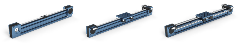
Belt-driven linear actuators are used for light and medium duty applications that require high speed and high acceleration.
Design and Construction
The assembly consists of two concealed timing belt pulleys, bolted at the extremities of a 45 × 90mm extrusion. The end-supports allow motor mounting options for any of Vention’s NEMA 34 stepper motors on both sides. All lengths and configurations include a zero backlash steel-reinforced polyurethane timing belt. The timing belt’s open ends can be joined and tensioned using Vention’s timing belt tensioner for installation under any gantry plate. Add plastic bumpers on each end to protect the equipment. Bumpers also have a feature to mount M18 sensors for end of travel detections.
Available Lengths
Timing belt drives are listed as MO-LM-016-XXXX, where the notation “XXXX” in the part numbers corresponds to the extrusion length, ranging from 585mm to 1530mm in increments of 45mm, as well as length of 1980mm and 2295mm.
Roller Wheel or Linear Bearing Configurations
Gantry loads can be supported by roller wheels or linear bearings, depending on the application. Roller wheels are made out of glass-filled nylon and use the extrusion’s V-shaped groove as guides. The linear bearings can be mounted to the same gantry plates and use 16mm hardened steel shafts directly mounted on the extrusion with support blocks. The shafts are available in the following lengths: 585, 855, 1530 and 2295mm.
Additional lengths available on request, contact support@vention.io for more info.
Rack and Pinion Linear Actuator Overview
Rack and pinion linear actuators are used for light and medium duty applications that require any combination of high speed, high acceleration, and high load.
Design and Construction
The assembly consists of rack segments mounted within the T-slot of Vention extrusion which mesh with a pinion. The pinion is mounted inside a housing which doubles as an enclosure for the pinion, shaft, and bearings. The housing also functions as a sturdy gantry plate capable of connecting to extrusions, assembly plates, other gantries, and many other Vention parts. The housing allows motor mounting options for any of Vention’s NEMA 34 stepper motors or Vention’s planetary gearbox on either side. 6061-T6 aluminum end stops protect the equipment and operator in case of actuator collision with the end stops. The end stops also have a feature to mount M18 sensors for end of travel detections.
Available Lengths
Rack segments are listed as MO-LM-020-XXXX, where the notation “XXXX” corresponds to the segment lengths of 540mm or 810mm. These lengths are designed to be installed in series to allow for a wide range of actuator lengths.
Roller Wheel or Linear Bearing Configurations
Pinion Housing loads can be supported by roller wheels or linear bearings, depending on the application. Roller wheels are made out of glass-filled nylon and use the extrusion’s V-shaped groove as guides. The linear bearings can be mounted to the same housing and use 16mm hardened steel shafts directly mounted on the extrusion with support blocks. The shafts are available in the following lengths: 585, 855, 1530 and 2295mm.
Additional lengths available on request, contact support@vention.io for more info.

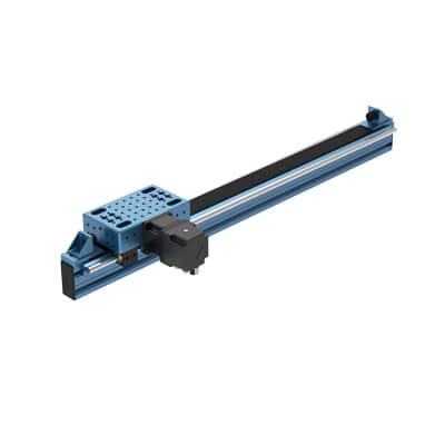
Belt Rack Linear Actuator Overview
Belt rack linear actuators are used for light and medium duty applications that require any combination of high speed, high acceleration, and high load.
Design and Construction
The assembly consists of rack segments mounted to the T-slot of Vention extrusions that mesh with the belt. A pulley mounted inside the housing also meshes with this belt. As the pulley turns, the housing is pulled along the stationary belt. Because the belt is pushed into rack segments, the actuator’s rigidity is high. The housing also functions as a sturdy gantry plate capable of connecting to extrusions, assembly plates, other gantries, and many other Vention parts. The housing allows motor mounting options for any of Vention’s NEMA 34 stepper motors or Vention’s planetary gearbox on either side. 6061-T6 aluminum end stops allow the mounting of rubber bumpers which protect the equipment and operator in case of actuator collision with the end stops.
Available Lengths
Rack segments come in 180mm lengths, allowing any interval of 180mm actuators to be assembled.
Roller Wheel or Linear Bearing Configurations
Pinion Housing loads can be supported by roller wheels or linear bearings, depending on the application. Roller wheels are made out of glass-filled nylon and use the extrusion’s V-shaped groove as guides. The linear bearings can be mounted to the same housing and use 16mm hardened steel shafts directly mounted on the extrusion with support blocks. The shafts are available in the following lengths: 585, 855, 1530 and 2295mm.
Additional lengths available on request, contact support@vention.io for more info.
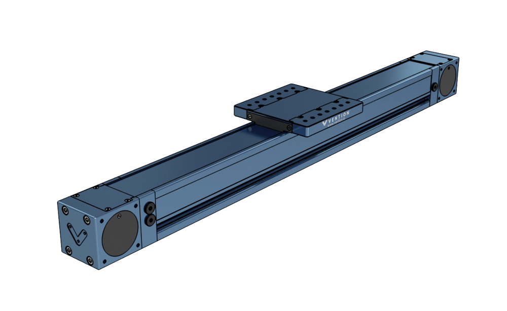
Enclosed Timing Belt Overview
The enclosed timing belt actuators are used for medium duty applications that require any combination of high speed, high acceleration, and high load. The actuator series is also attractive because of its resistance to dirty working environments and its pinch point free design.
Design and Construction
The assembly consists of a fully enclosed guide and drive system within a specialized extrusion. The gantry plate is mounted on a large linear profile guide bearing capable of supporting large loads and moments. The actuator comes in both standard duty (MO-LM-026-XXXX) and heavy duty (MO-LM-027-XXXX) which is equipped with double the bearings. The gantry plate is driven by a 20mm wide HTD8 timing belt which comes pre-tensioned and has full 180 degree engagement with all pulleys, ensuring belt skip will not occur. The contents of the actuator are mounted on a proprietary U shaped extrusion and are enclosed by a hardened 1095 spring steel cover strip. The enclosed nature of the actuator means it is suitable for dirty environments as well as use cases where the designer wants to minimize or eliminate pinch points.
Available Lengths
Both versions of the actuator (standard and heavy duty) come in 5 different extrusion lengths: 585mm, 855mm, 1530mm, 2295mm and 3330mm. The last 4 digits of the part number indicate the length of the actuator’s extrusion. For example, MO-LM-026-0855 would be a standard duty enclosed timing belt with a 855mm length extrusion body.
Configurations
As previously mentioned, this actuator comes with all components included. There are two possible configurations: standard duty and heavy duty. The differentiating features between them are the number of linear profile guide bearings as well as the size of the gantry plate. The standard duty uses a single bearing block and has a gantry plate with a 180x180mm footprint; the heavy duty actuator uses two bearing blocks for increased load capabilities and has a 270x270mm gantry footprint.
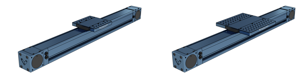
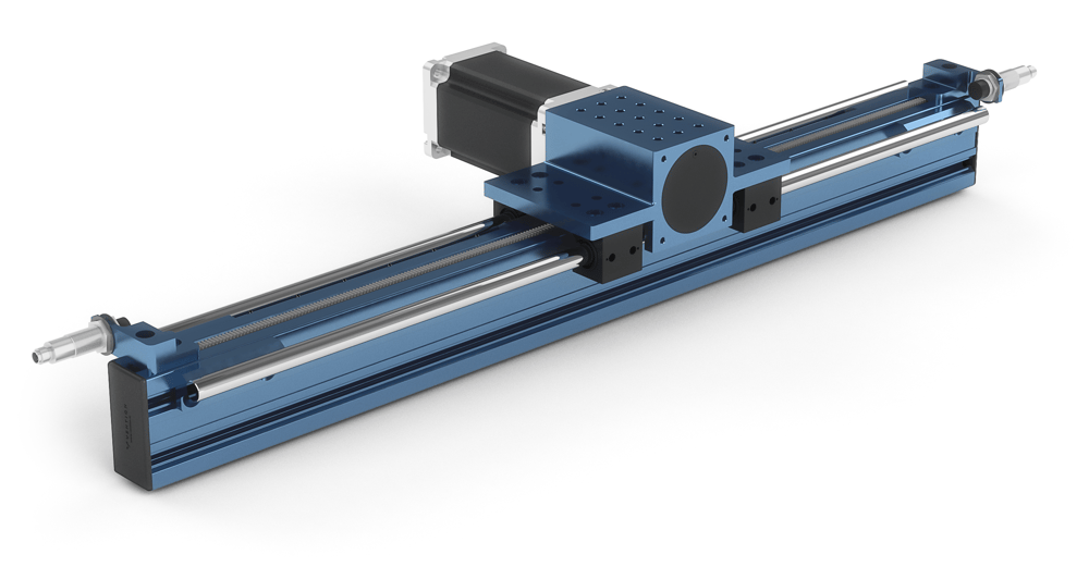
Enclosed Ball Screw Overview
The enclosed ball screw actuator is ideal for high load and high precision applications such as CNC routing, vertical cobot palletizing, heavy duty range extenders, etc. The actuator series has an enclosed design thanks to its cover strip which makes it suitable for dirty work environments by mitigating dust ingress. The enclosed design also removed pinch points, making it more user friendly.
Design and Construction
The assembly consists of a fully enclosed guide and drive system within a specialized extrusion. The gantry plate is mounted on a set of 20mm series linear profile guides. The gantry is connected to the guides vis four bearing carriages capable of supporting large loads and moments. The gantry plate is driven by a 15mm diameter ball screw with a 16mm lead, producing high force output. The contents of the actuator are mounted on a proprietary U shaped extrusion and are enclosed by a hardened 1095 spring steel cover strip. The enclosed nature of the actuator means it is suitable for dirty environments as well as use cases where the designer wants to minimize or eliminate pinch points.
Available Lengths
5 different extrusion lengths are available: 360mm, 585mm, 855mm, 1530mm, and 2295mm. The last 4 digits of the part number indicate the length of the actuator’s extrusion. For example, MO-LM-039-0855 would be an enclosed ball screw with a 855mm length extrusion body. For travel length, refer to the technical documentation for the enclosed ball screw linked at the bottom of the document.
Configurations
The enclosed ball screw actuator comes with all components pre-assembled. Simply add the home and end sensors in the locations you desire and attach the motor of your choice to the motor coupling. The actuator is available in a single configuration with the above mentioned lengths.

Technical Characteristics
| Timing Belt | Rack and Pinion Linear | Enclosed Timing Belt | Enclosed Ball Screw | Belt Rack | |
|---|---|---|---|---|---|
| Characteristics | 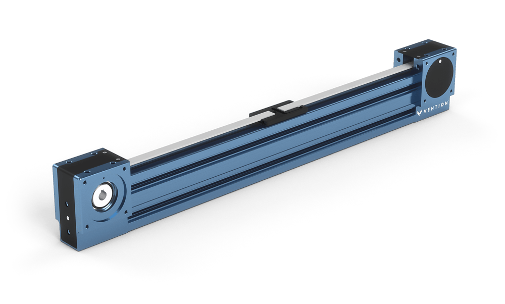 |
 |
 |
|
|
| Typical Applications | High Speed Applications
|
High-speed, High-load Applications
|
High-speed, High-load Applications, Dirty Environment, and Pinch Point Free
|
Precise, High-load Applications, Dirty Environment, and Pinch Point Free
|
High-speed, High-load Applications
|
| Available Lengths | 585mm to 1530mm in 45mm increments + 1980mm, 2295mm. Net displacement is equivalent to the extrusion length minus the gantry’s longitudinal dimension |
Combinations of 540mm & 810mm. Net displacements are equivalent to total segment length minus 190mm to account for housing and end stops |
585mm, 855mm, 1530mm, and 2295mm. Net displacements are equivalent to length minus 125mm for the standard version and length minus 245mm for heavy duty |
360mm, 585mm, 855mm, 1530mm, and 2295mm. Net displacements are equivalent to length minus 215mm. |
180mm Increments. Net displacements are equivalent to total segment length minus 275mm to account for housing and end stops. |
| Compatible Gantries |
|
N/A | N/A | N/A | N/A |
| Compatible Guides | Linear bearings (MO-LM-010-0001) on 16mm hardened steel shaft (MO-LM-014-XXXX)
|
N/A | N/A | Linear bearings (MO-LM-010-0001) on 16mm hardened steel shaft (MO-LM-014-XXXX)
|
|
| Displacement Ratio (mm/turn) | 150 | 157.08 | 208 | 16 | 125 |
| Linear Force / Torque Ratio (N/Nm) | 42 | 40 | 30 | 360 | 30 |
| Typical Load and Speed (N @ mm/s)* | 125 @ 1250 | 150 @ 1250 | 200 @ 500 | 2000 @ 75 | 125 @ 1250 |
| Typical Load and Speed Using 5:1 Gearbox (N @ mm/s)* | 700 @ 250 | 600 @ 300 | 550 @ 300 | N/A | 500 @ 250 |
| Repeatability (mm) | 0.025 | 0.25 | 0.025 | 0.025 | 0.025 |
| Back Drive Resistance | Low | Low | Medium | Medium | Low |
| Motor Compatibility | NEMA 34, 14mm shaft, 5mm keyway |
*for detailed performance of speed vs linear force, please refer to the technical documentation of each actuator type.
Calculating Actuator Forces
It is important to calculate the forces that your machine will be subject to which includes the loads on the actuator. The forces present are dependant on the assembly but here we will discuss some basic factors to consider when calculating the forces applied to actuators.
As a general practice, a safety factor should also be used to ensure that any uncertainties and variables won’t make or break the operation of an actuator. A recommended safety factor of 1.2 should be used when calculating these forces.
Horizontal actuators:
When calculating the operating loads of a horizontal actuator the main consideration is simply the payload of the actuator and how much acceleration will be required to perform the intended operations.
F = ma
Therefore, it is as simple as knowing the mass (kg) of the moving section of the actuator and its desired acceleration (m/s²). Friction in the system is a factor to consider however it is very low and is highly assembly dependant. This makes it difficult to provide a general calculation for all actuators and instead can be absorbed into the use of a safety factor.
Vertical actuators:
Lifting a mass vertically is more challenging than horizontally because the actuator must fight the acceleration of gravity, not just the desired accelerations of the actuator. The updated force calculation for vertical actuators is:
F = m(a + 9.81 m/s²)
This equation is like that used for horizontal payloads with the addition of the acceleration of gravity 9.81 m/s².
Example:
If a 2-axis system, one horizontal and one vertical, is being designed with the following performance characteristics:
- 2 m/s² horizontal acceleration
- 1 m/s² vertical acceleration
- 50 kg payload
- Safety factor of 1.2
Using these values, we can easily calculate the required horizontal actuator and vertical actuator forces:
Fh = 1.2 X 50kg X 2m/s² = 120N
Fv = 1.2 X 50kg (1m/s² + 9.81 m/s²) = 645.6N
Selecting the Right One
The figure below demonstrates a comparison of the linear force output as a function of the linear speed of the ball screw, belt-driven, and rack and pinion linear actuators. The forces shown in this diagram are approximate and should be used as a general reference. For specific force, values visit the technical documentation of the specific actuator type.
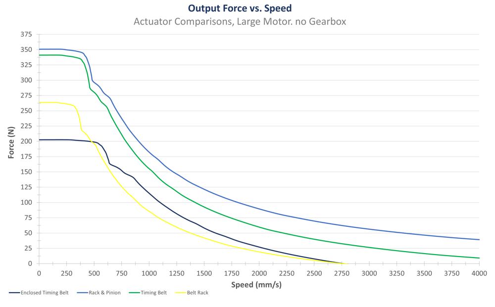
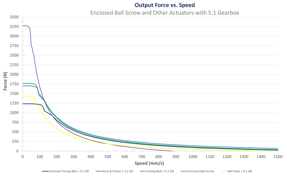
Observing the ball screw actuator’s behavior from the graph and table above, its maximum force capacity sharply decreases as linear velocity increases. In comparison, when observing the other actuators, the maximum force capacity slowly declines as linear velocity increases, remaining relatively consistent at all speeds. Note that all actuators in this graph except for the ball screw can be equipped with a reduction gearbox and are represented by the dashed lines.
Consequently, if your application requires higher force capacities, higher torque, and higher precision, we recommend the ball screw or one of our other actuators equipped with a reduction gearbox. For higher speeds, we would recommend a timing belt, rack and pinion, or enclosed timing belt without the reduction gearbox. Finally, if your application requires very long axes (more than 3.33 meters), we recommend the rack and pinion due to its modular nature.
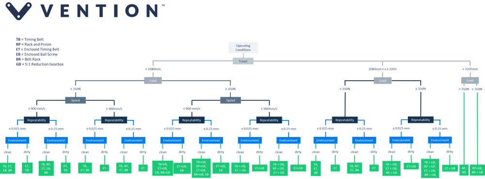
For more help selecting your linear actuator, make sure to use the flowchart below to help you narrow down your options:
For more details on each actuator we recommend that you visit their respective Technical Data Sheets:
Timing Belt Actuator Datasheet
Rack and Pinion Actuator Datasheet
Enclosed Timing Belt Actuator Datasheet
Enclosed Ball Screw Actuator Datasheet