Timing Belt Actuator
Contents
Overview
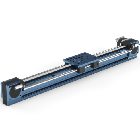
Belt-driven linear actuators are typically used for light to medium duty applications that require higher speeds and acceleration. Consisting of two concealed timing belt pulleys mounted at the ends of a Vention 45 x 90 mm extrusion, the assembly can accommodate any of Vention’s Nema 34 stepper motors and comes in a variety of lengths.
Compatible Guides
The belt-driven linear actuator can drive a variety of gantries that are in turn supported by both Eccentric and Concentric V-shaped rollers (MO-LM-001-0027/0028) or linear bearings on shafts (MO-LM-014-XXXX). Both configurations can be seen below.
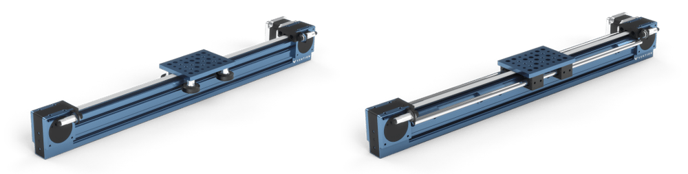
| Exhibit 1. Belt-driven linear actuator shown with medium gantry and nylon V-shaped wheels | Exhibit 2. Belt-driven linear actuator shown with medium gantry and linear bearings and shafts |
Applications
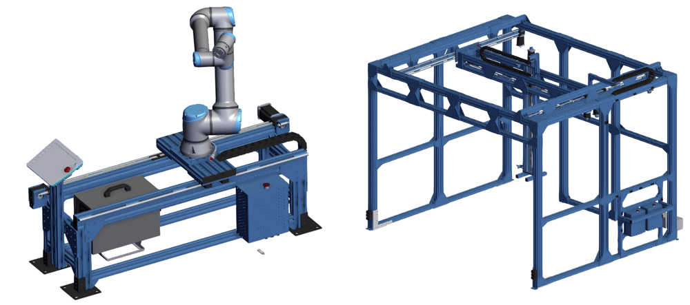
There are several application for belt-driven linear actuators, including a UR10 7th Axis or a 3-Axis Palletizer.
Technical Specifications
| Available Lengths | 585mm to 1530mm in 45mm increments + 1980mm, 2295mm Net displacement is equivalent to the extrusion length minus the gantry’s longitudinal dimension |
| Displacement Ratio (mm/turn) | 150 |
| Linear Force / Torque Ratio (N/Nm) | 42 |
| Maximum input torque (Nm) | 61 |
| Output Force Capacity (N) | See Exibit 3 & 4 below |
| Repeatability including backlash (mm) | ±0.3 |
| Total Backlash (mm) | 0.25 |
| Back Drive Resistance | Low |
| Motor Compatibility | NEMA 34, 14mm shaft MO-SM-001-0001, MO-SM-002-0001, MO-SM-003-0001 |
| Sensor Compatibility | Compatible with all M18 sensors using the left or right end stops(MO-LM-015-0001/0002) |
| Belt Life (hours) | 6000-11000 |
The figure below demonstrates the linear force output in function of the linear speed of the belt-driven linear actuator. This was calculated using Vention’s NEMA 34 stepper motors driven by MachineMotion 2.
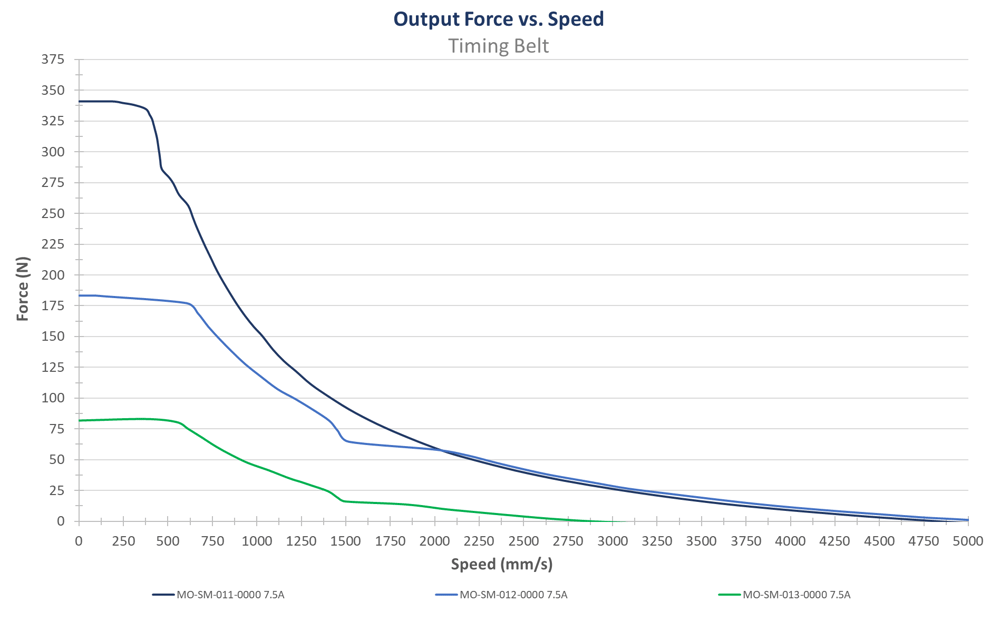
Observing the figure above, the force slowly decreases as the linear velocity increases, making the timing belt actuator ideal for lower force applications that require higher movement speeds. If more force is required and travel speed is not as critical, consider adding a gearbox to the powertrain. See the below figure for expected performance with a gearbox.
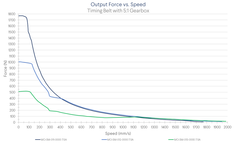
Observing the figure above, the force is much higher when using the gearbox, however it decreases much faster as the linear velocity increases. This makes the combination ideal for slower moving applications with higher forces.
Note: During MachineMotion’s boot up sequence, the holding force is momentarily 65% of its rated value. Please keep in mind when using in vertical and/or angled applications.
Assembly Instructions
Motor Installation
The Timing Belt Actuator comes pre-assembled with the only remaining task of installing the selected powertrain components and guiding system.
To connect powertrain components (stepper motor, brake and gearbox), perform the following steps:
- Remove the motor cover on the actuator endblock, to install the stepper motor.
- Optional: If you have a brake or gearbox, connect them to the output shaft of the stepper motor using the provided M6 X 20mm fasteners.
- Connect your stepper motor to the actuator using x4 M6 X 20mm fasteners (HW-FN-005-0020).
Notes:
- When installing motors, apply a small amount of grease to the motor shaft so that it is lightly coated. This will reduce the possibility of fretting corrosion occurring during operation, making future removal easier.
- Moreover, do not use excessive force (hammering, prying or using screws to “push” the motor) to install the motor.
Linear Guide Installation
Install the guiding system and gantry plate of your choice. If using linear guide rails, install both rails followed by sliding the bearing carriages on the guide rails and finally attaching the bearings together using a gantry plate. Be careful to use the short M8 fasteners included with the bearings or the cartridge can be damaged.
If using roller wheels, attach the roller wheels to the gantry plate while it is in place on the extrusion. Adjust the eccentric rollers until there is no lateral play but rolling motion is still smooth.
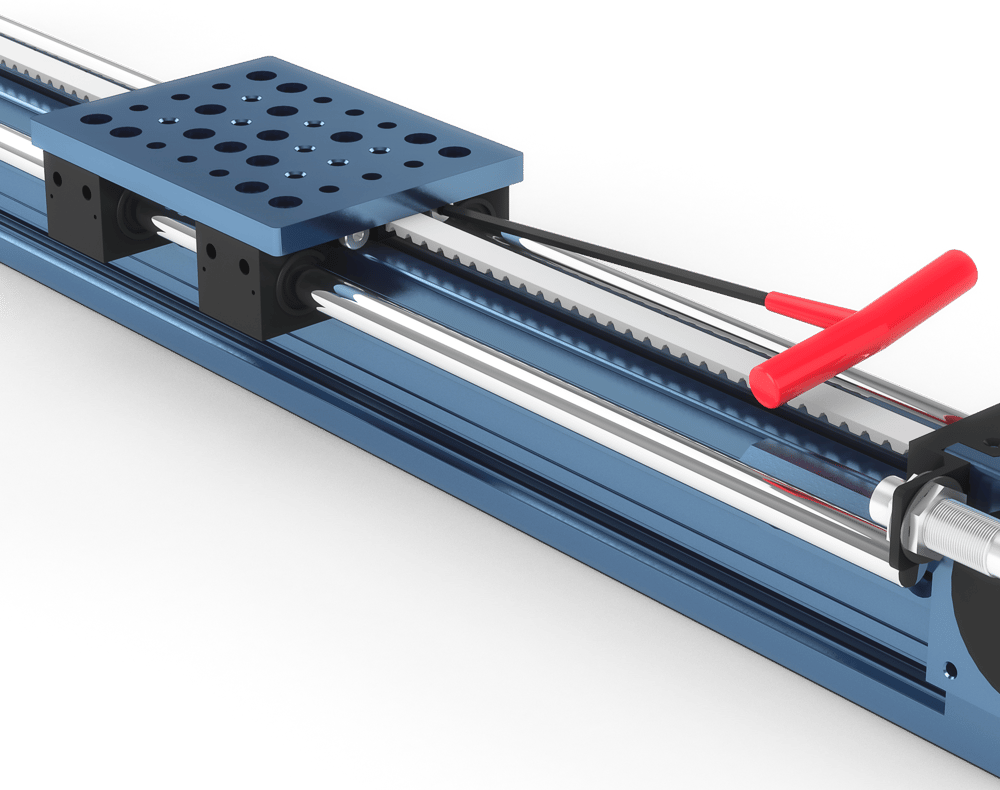
Finally, attach the belt tensioner to a counterbore in the middle of your gantry plate.
Sensor Installation
Sensors can be installed in four configurations on the actuator using the Left/Right Timing Belt Sensor Bumper (MO-LM-015-0001/0002). To install a sensor, screw the sensor all the way into the hole until it bottoms out. Install one jam nut on either side of the sensor and tighten them to lock the sensor in place.
Note: The only sensor compatible with the actuator is the non-flush inductive proximity sensor (CE-SN-004-0001).
Tensioning
To tension the timing belt, locate the two screw heads under the gantry and use a hex key to tighten both screws equally until desired belt tension is reached.