Belt Rack Actuator
Overview
The belt rack actuator offers high speeds, high linear forces, good accuracy, and modularity.
Configure it to suit your needs; this actuator has two options for linear guides, four for sensors, and six for powertrains, plus the ability to add a brake or locking handwheel.
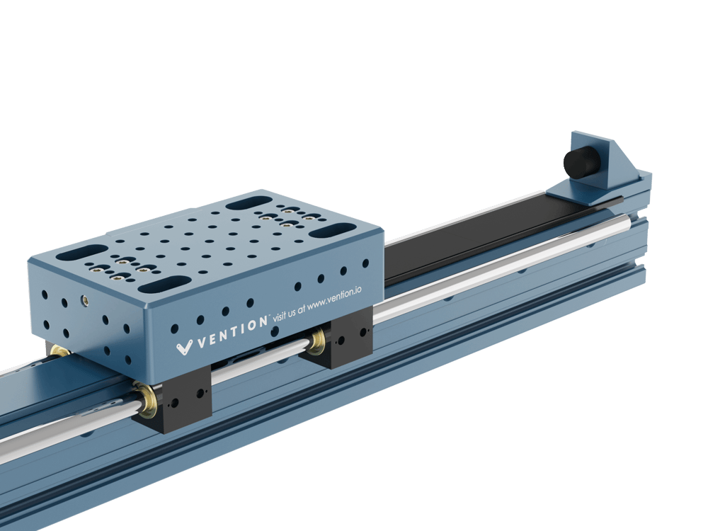
Composition
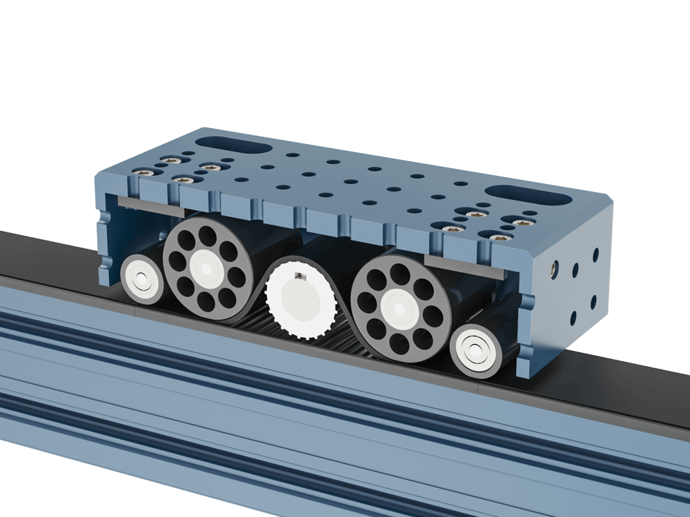
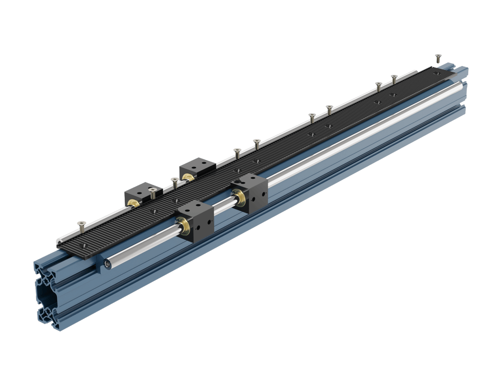
What’s the difference between a belt rack actuator and any other belt actuator? The belt rack actuator has a fixed rack attached to the extrusion. It works like a ladder, which the belt engages with and uses to pull itself along.
In a standard belt rack configuration, the motor and carriage move together while the belt is fixed in place with the extrusion. By contrast, with our other belt actuators (enclosed timing belt actuator) the motor is fixed in place and the belt moves with the carriage.
Other belt actuators rely on the belt being clamped at both ends—whereas the rack allows there to be a much shorter length of belt under tension. This increases stiffness, which improves positional accuracy and allows longer actuators to be built.
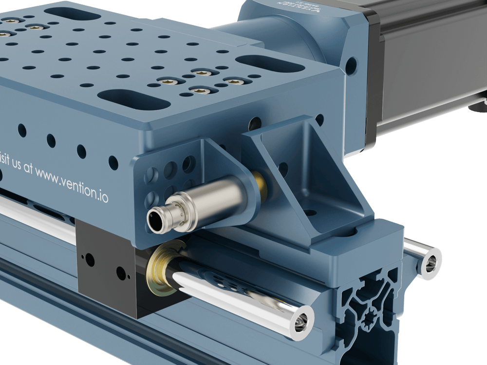
Two sets of idler wheels are mounted inside the belt rack housing. They function as belt tensioners and increase the contact with the driving pulley.
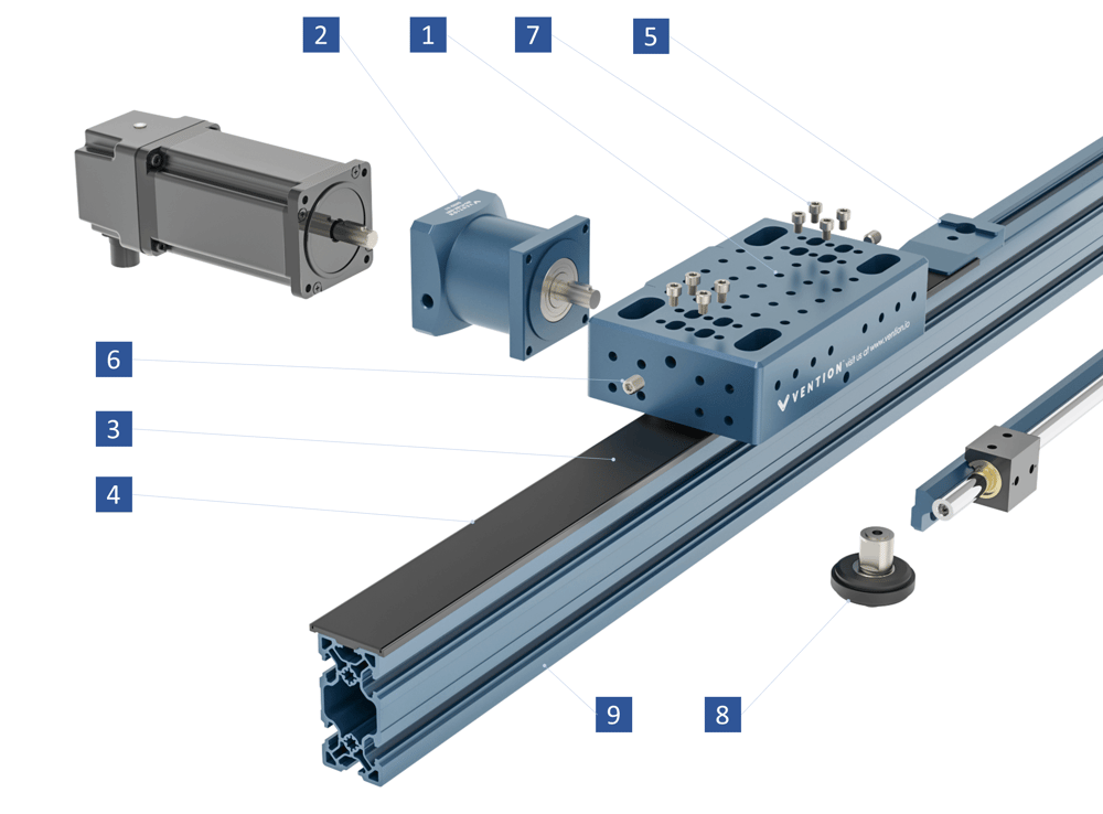
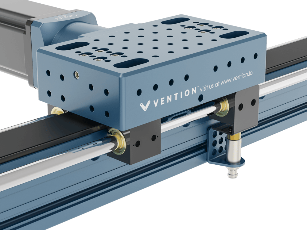
- A series of M8 x 1.25 threaded holes in the housing let you attach a wide variety of Vention parts to the actuator.
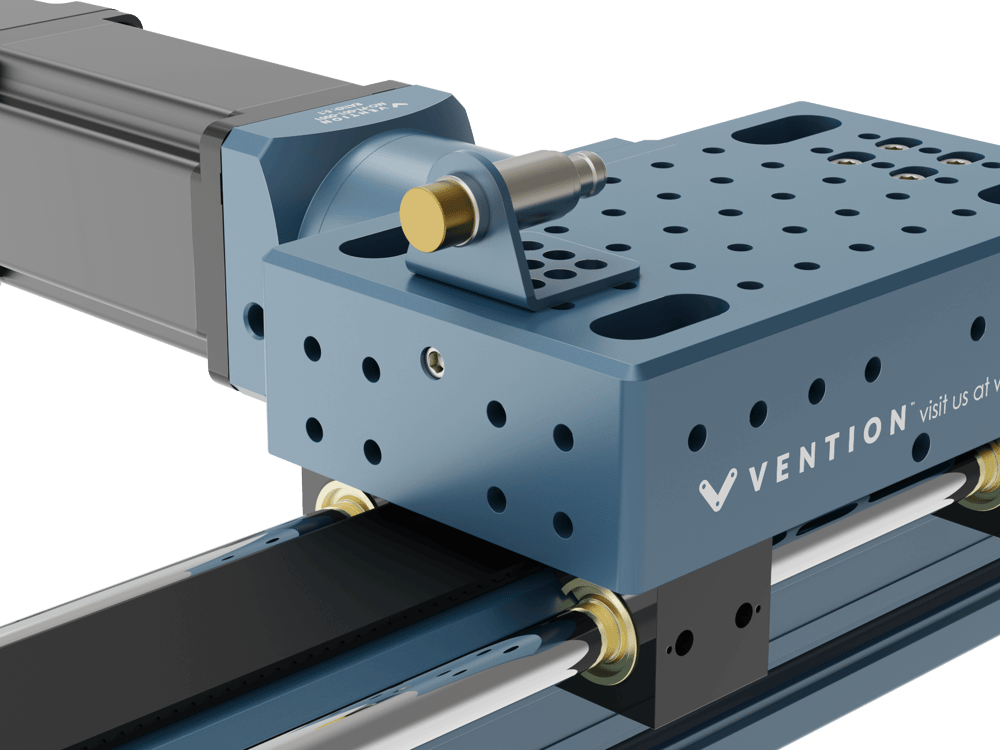
- NEMA 34 motor or gearbox mount.
- A 50-mm wide belt provides high rigidity, strength, and a long service life. It’s mounted tooth-side down, which reduces the risk of contaminants affecting its performance.
- Each rack segment is 180 mm long and made of high-strength plastic. They’re mounted to the extrusion with two screws.
- Two belt clamps, one at each end of the actuator, hold the belt in place and serve as mounts for end stops.
- Two set screws let you adjust the belt tension.
- Eight locking screws fix the tensioner in place.
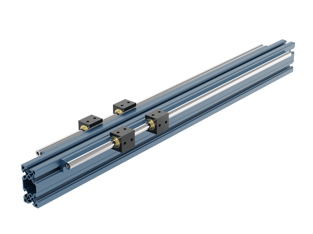
- A set of either roller wheels or linear bearings and shaft guide the actuator.
- Mounting options: The actuator can be assembled on 45 x 45 mm, 45 x 90 mm or 90 x 90 mm Vention extrusions. The most common is 45 x 90 mm.
Applications
Flexible orientations
In general, this actuator can provide motion in any of the cartesian directions and at any angle. It can be mounted with the belt facing up, down, or sideways.
Either the extrusion or the motor and housing can be fixed in place. When the extrusion is fixed, the motor and housing will move along the actuator. When the latter are fixed, the extrusion moves.
Robot range extenders
Use robot range extenders to move a robot between workstations. Range extenders built using belt rack actuators are accurate, fast, and can have long ranges.
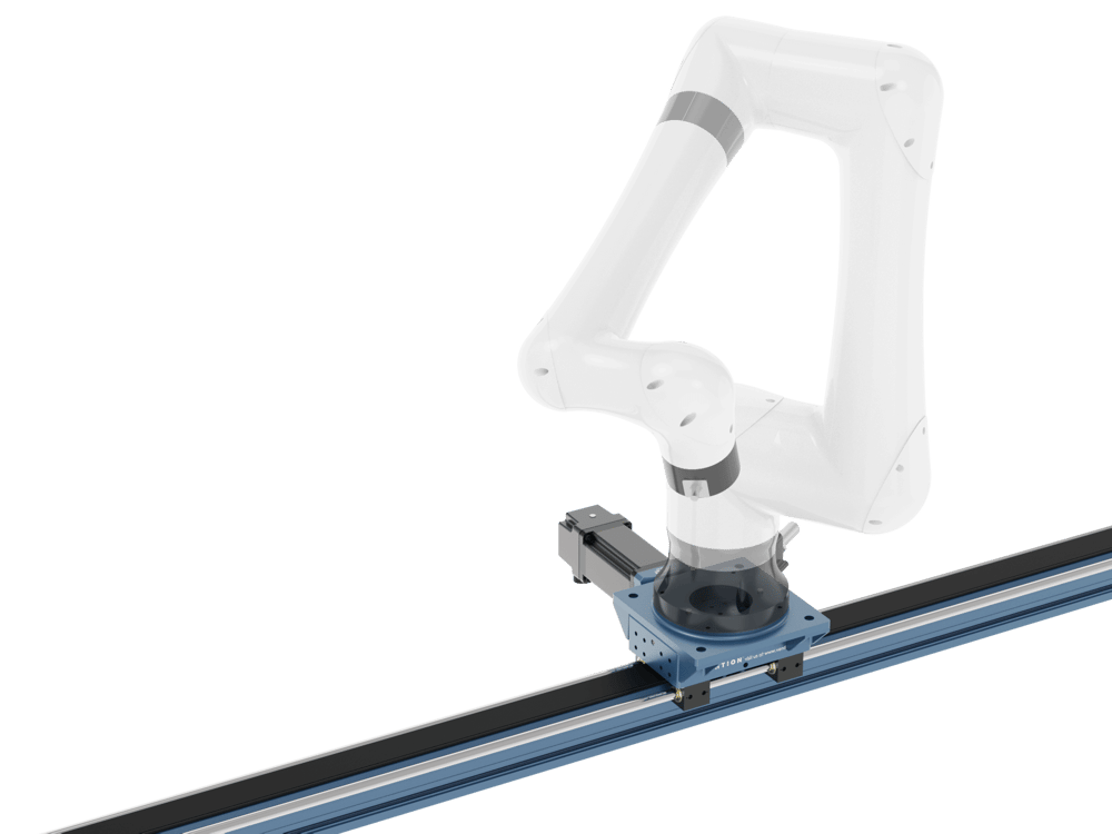
Typically a carriage is built on top of the belt rack housing, which increases the distance between linear bearings and allows even large cobots to be mounted.
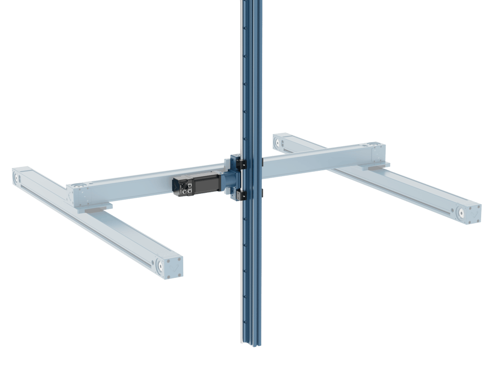
Z-axis systems
Z-axis systems are used in applications like cartesian palletizers. They typically have the housing fixed to a gantry while the extrusion travels up and down to move the tool vertically.
This configuration is ideal because it allows the actuator to clear objects inside the machine such as conveyors, pallets, and goods. Using a 5:1 reduction gearbox, the actuator can lift up to 167 kg.
Technical Specifications
Tech specs
| Displacement ratio | 125 mm/turn |
| Force per unit of input torque (N / Nm) | 50.3 |
| Maximum input torque (Nm) | 32.6 |
| Max allowable Peak Axial Force (N) | 1800 |
| Max lifting capacity | 167 kg |
| Repeatability including backlash (mm) | ±0.3 |
| Total Backlash (mm) | 0.25 |
| Motor compatibility | NEMA 34, 14-mm shaft with 5-mm key |
| Sensor compatibility | Inductive proximity sensors with mounts |
| Length modularity | 180 mm increments |
| Maximum Length (belt facing up) | 3420 mm |
| Maximum Length (other directions) | 1800 mm |
Compatible guide
The belt rack actuator requires external linear guides in order to function properly. You can use either roller wheels or linear bearings. Read our linear guides techdoc to learn more. Note that at least four guiding elements are required.


Compatible accessories
Use the belt rack actuator with Vention’s 5:1 gearbox, right-angle gearbox, power-off brake, and/or locking hand wheel.


If you’re using this actuator in a z-axis application, we strongly recommend adding a shock absorber. It helps prevent the actuator from getting damaged in the event of a power failure.
Load capacity
The load capacity of the housing depends on the type of guides used. Linear bearings can support a higher load than roller wheels.
The spacing between guiding elements affects the allowable moment forces, and the number of guiding elements dictates the allowable linear forces in each cardinal direction. For a full breakdown of how to calculate each, see our linear guides techdoc.
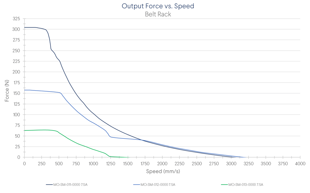
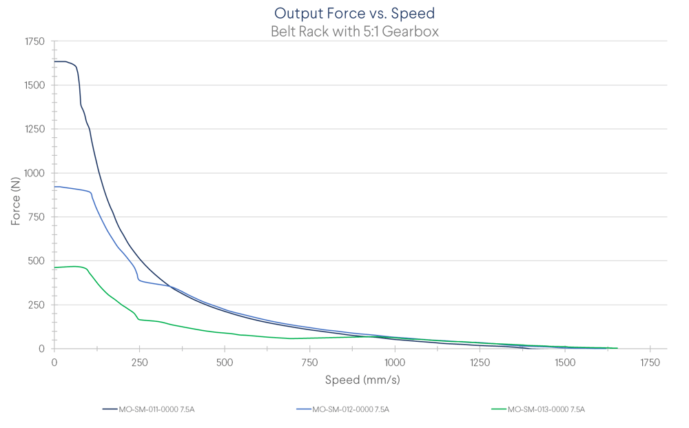
Driving Force
The belt rack actuator can be configured with six different combinations of motor and gearbox. Both the right-angle and standard gearboxes have a ratio of 5:1 and are considered to have the same force curve. In general, these gearboxes divide speed by five, but multiply force by five for a given motor speed.
If you know how much speed and force your application needs, the charts below will help you decide if you’ll need a gearbox. Select a motor and gearbox configuration that ensures that the desired speed and force fall under the curve.
Note: During MachineMotion’s boot up sequence, the holding force is momentarily 65% of its rated value. Please keep in mind when using in vertical and/or angled applications.
Design Tips
Adding end stops
Unlike enclosed actuators, this actuator requires an additional end stop. Rubber bumper can be mounted to act as an end stop.
Placing sensors
Home and end position sensors inform MachineMotion of the axis zero location. Vention uses inductive proximity sensors for position sensing. It’s critical to design their mounts properly for precise and safe operation. First, the sensors must not be able to collide with other parts of the machine. Second, the sensor must trigger on a flat metal surface, such as a plate, gusset, or extrusion.
There are many options for mounting sensors. Below are a few examples.
Another thing to consider is the cable that attaches the sensor to the motor. It’s often easier to mount the sensors to the housing or gantry system. That way, you don’t need to pass the sensor cables through a drag chain attached to the motor, which reduces the amount of cabling required.
Assembly
Assembling a belt rack is a simple process that takes about an hour, depending on the actuator length.
1. If using linear bearings, attach their shafts on either side of the extrusion. Then slide the linear bearings onto the shaft.
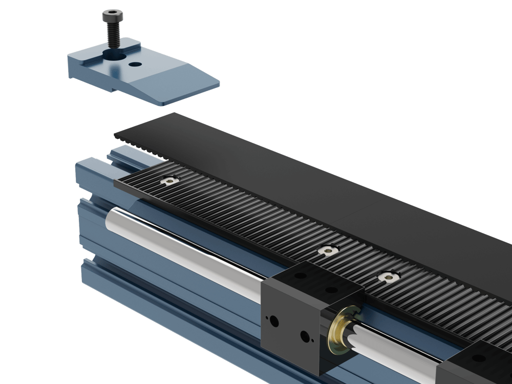
2. Attach each rack segment to the extrusion with the provided M6 flat-head screws.
Important: Leave these loose so that the rack can slide along the extrusion slightly. The screws will be tightened later.
3. Tighten the first rack segment in its final position.
4. Place the belt, teeth side down, into this first rack segment. Its cut end should be flush with the end of the rack. Secure it in place with the clamp and M8 x 18 mm bolt. (HW-FN-003-0018 & MO-LM-042-0011).
5. Push the belt down on the second rack, a clamp will help to hold it in place. For belt rack actuators above 2m in length, two clamps will be needed to help keep the belt in place during assembly. When the belt is clamped down, the rack will move slightly so that a roughly 1-mm gap appears between the first and second segments (see arrow). Tighten the second rack segment in place. Tighten the bolt furthest from the first rack segment, then peel back the belt in order to tighten the second bolt.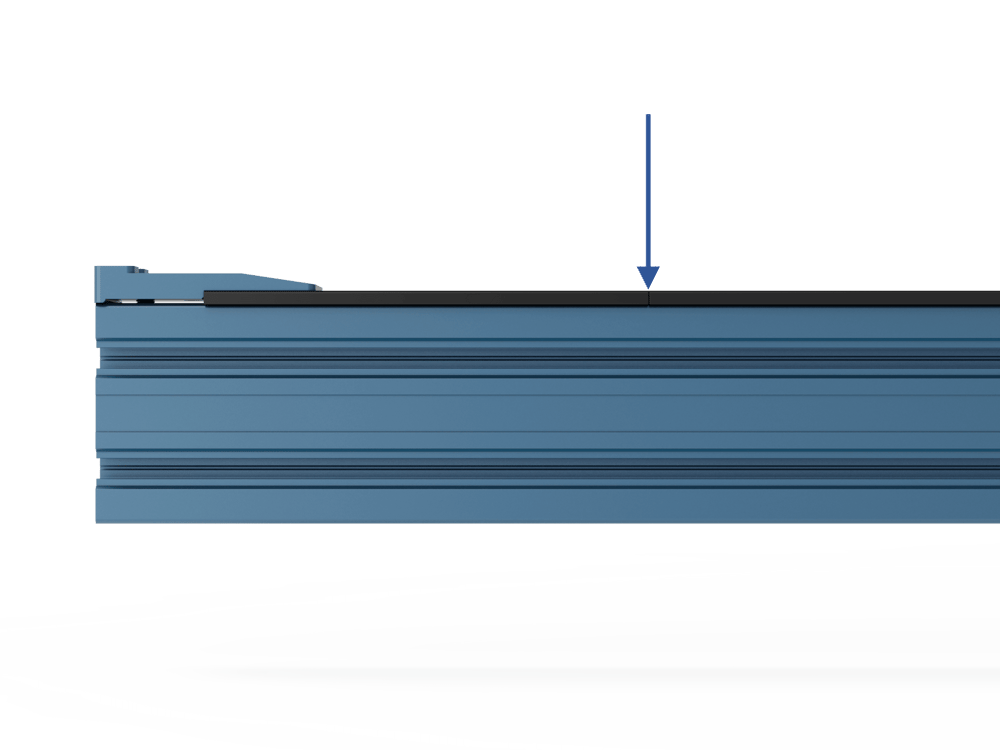
6. Check that the belt still fits well into the second rack when pushed down. If not, repeat step 5.
7. Repeat steps 5 and 6 one more time, so that three rack segments are fixed to the extrusion with the proper gap.
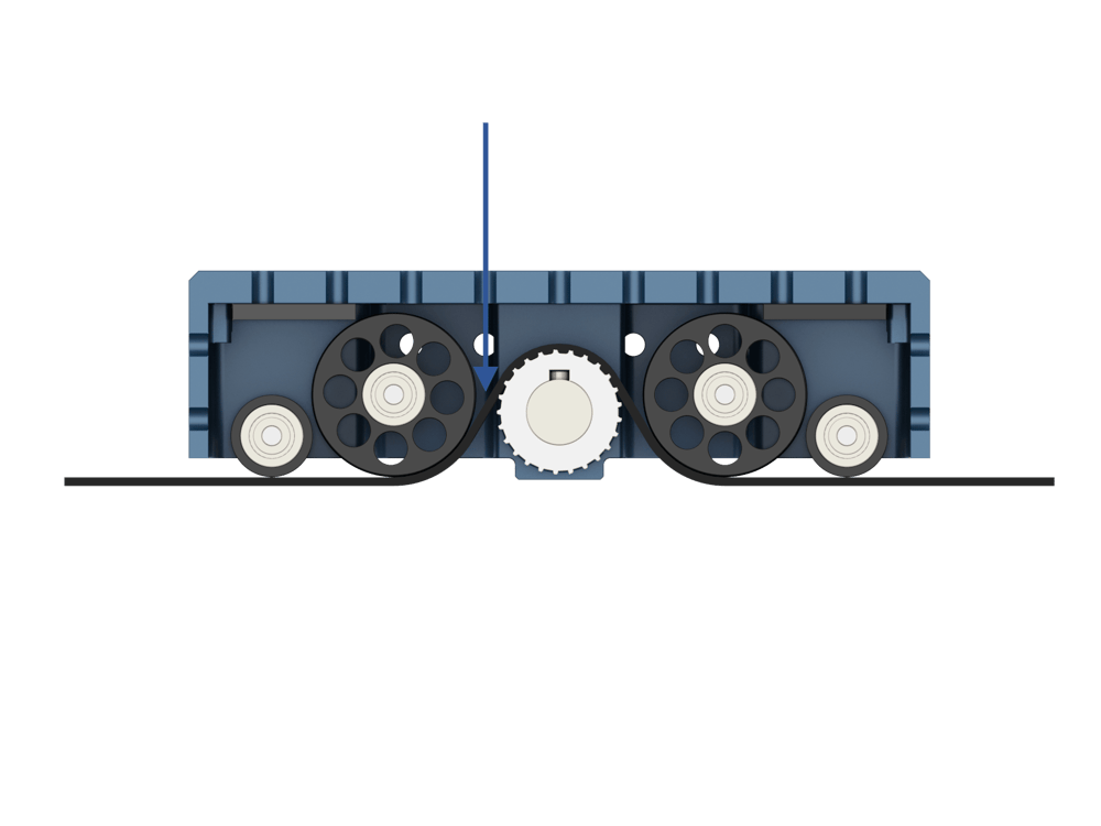
8. Thread the belt through the housing as shown. Using a 5 mm Allen key(arrow in picture below), push the belt up between the drive pulley and the large idler. If this is not possible, use the 5 mm Allen key to remove the idler assembly (four bolts on the top of the housing).
9. Gently pull the loose end of the belt taught. It is not necessary to pull with much force, but keeping the belt tight at this step will help ensure the teeth mesh properly between the drive pulley, rack segments and belt. Mesh the belt and rack together by lowering the housing assembly and belt onto the rack segment.
10. Attach either linear bearings or roller wheels to the housing using M8 x 12 mm screws.
11. Attach the next rack segments:
- Move the next rack segment flush with the end of the previous one.
- Clamp the belt down on either side of the joint.
- Tighten the accessible screw.
- Remove the clamp on the new segment and tighten the screw
- Move the free clamp to the next segment, then remove the other clamp and move it to the new joint. Always “leapfrog” the clamps, never leaving the belt unclamped. This will keep the belt under a slight amount of tension. This ensures that new rack segments are aligned properly.
12. Repeat step 11 until all rack segments are attached.
13. Attach the second belt clamp.
14. Tighten the idler set screws on the housing to approximately 1Nm. Cycle the actuator and check that it runs smoothly, increase or decrease the tension until the actuator runs smoothly.
15. Attach the motor or powertrain components.
Notes:
- When installing motors, apply a small amount of grease to the motor shaft so that it is lightly coated. This will reduce the possibility of fretting corrosion occurring during operation, making future removal easier.
- Moreover, do not use excessive force (hammering, prying or using screws to “push” the motor) to install the motor.
16. Attach any accessories, such as sensors or end stops.
Maintenance
For maintenance instructions, please see the maintenance tech doc.
```