Vention Linear Axis Alignment Procedure
Adhering to this procedure is necessary to ensure a properly functioning linear motion system. Failure to properly align a linear axis system will lead to premature failure and poor performance.
Before you start
- Never work on equipment that is energized.
- Always follow proper lockout procedures as well as all local safety rules and regulations.
- Make sure to use the proper safety equipment at all times.
- Always ensure your workspace allows for adequate room to work around your equipment.
When to do alignment?
If your equipment arrives at your location pre-assembled, or if you’re performing the assembly yourself, you will have to complete the alignment procedure once you have positioned your equipment at its desired place of operation.
Can I Avoid Alignment?
Yes, it can be avoided in some cases by using the procedures detailed in the Vention Self Aligning Mounts technical document. This product allows for positional misalignment of ±3mm and ±6.5° which allows mounting of linear guiding systems using common tools like a measuring tape and carpenter’s level. Read this technical document in detail to assess if this product is a good solution for your application.
Step 1: Leveling The Structure
Alignment is done after completing the assembly of your machine structure, but before installing the gantry onto the guide rails. Uneven flooring or slight inaccuracies in the base structure must be corrected for optimal system performance and longevity. To level your structure, use a precision machinist level (or any similar leveling measurement device) to evaluate the level of the machine along its length and its width. For larger structures, you will have to evaluate the level at both ends to ensure optimal results.
If your design uses…
- Leveling feet (HW-LF-001-0001, HW-LF-001-0002, or HW-LF-002-0000):
Adjust the height of each foot by turning the bottom shoulder joint hex nut clockwise or counterclockwise until a level structure is obtained. Then secure all jam nuts.

- Floor anchors (ST-SE-001-0003, ST-SE-001-0004, ST-SE-001-0005, or ST-SE-001-0008):
Place shims beneath each floor anchor as needed until a level structure is obtained. Then secure the anchors to the floor. To shim the structure you can use the shims included in the slotted shim kit.

Step 2: Aligning The guide Rails
MO-LM-010-XXXX & MO-LM-014-XXXX
The 16mm round rail linear guides have some degrees of freedom built into their design that makes alignment fairly easy. The only dimension that is still sensitive during installation is the spacing between the rails. Parallelism of the guide rails is critical for their proper function and to ensure that they do not experience premature failure.
To align the round guide rails, a fixed and floating guide rail method can be used. The fixed guide rail is securely fastened to the structure whereas the floating guide rail is only loosely fastened to allow some side-to-side motion.
Note: For simplicity’s sake, throughout the alignment procedure, the term guide rail includes the extrusion to which the linear shaft and its mounting blocks are affixed. The linear shaft and mounting blocks must always be securely fastened to the extrusion.
1. Establish which guide rail is fixed (you can choose either one), and ensure that all fasteners on the frame connectors and assembly plates securing the fixed guide rail are properly tightened.
2. Ensure that all fasteners on the frame connectors and assembly plates securing the floating guide rail are loose. You should be able to slightly move the guide rail by hand without having to apply any appreciable force.
3. Slide the linear bearings onto the linear shafts and install the gantry. The linear bearings mounted on the fixed and floating guide rails should be properly tightened on the gantry plates.
4. Move the gantry to one end of its travel length and tighten all fasteners on the frame connectors and assembly plates, securing that section of the floating guide rail. Always start by securing all frame connector fasteners first and finish with the assembly plates.
5. Move the gantry to the other end of its travel length and tighten all fasteners on the frame connectors as you move the gantry along the way. Only tighten the connections at the gantry, using it as the spacer for the rails. Always start by securing all frame connector fasteners first and finish with the assembly plates.
6. Once the floating rail has been securely fastened on the structure throughout its length, move the gantry up and down the length of the rails. If a satisfactory alignment has been achieved, you should feel a consistent application of force throughout the length of the rails. Sudden resistance suggests an alignment error, in which case you may need repeat the alignment procedure.
MO-LM-049-XXXX Mounted on ST-EXT-001/002/005-XXXX (Standard Extrusions)
The profile linear guides have very tight tolerances that need to be respected during installation. Because these bearings are completely rigid they must be very well positionally aligned in both height and width with parallel bearing surfaces. To achieve this, the process is somewhat similar to the procedure for the round rail bearing in that a fixed-floating process is used, however, much more precision and care is needed in the alignment process.
Note: For simplicity’s sake, throughout the alignment procedure, the term guide rail includes the extrusion to which the linear shaft and its mounting blocks are affixed. The linear shaft and mounting blocks must always be securely fastened to the extrusion.
1. Establish which guide rail is fixed (you can choose either one), and ensure that all fasteners on the frame connectors and assembly plates securing the fixed guide rail are properly tightened.
2. Ensure that all fasteners on the frame connectors and assembly plates securing the floating guide rail are loose. You should be able to slightly move the guide rail by hand without having to apply any appreciable force.
3. Slide the linear bearings onto the profile linear guides and attach them to your gantry structure. The linear bearings mounted on the fixed and floating guide rails should be properly tightened on the gantry plates. Because of the rigidity of the profile bearings, the position of the floating side will be fully driven by the fixed side.
4. Move the gantry to one end of the axis and take note of any gaps or movement of the floating side. Use 20mm Profile Rail Shims to fill gaps in the rails and 7/8” Slotted Shims for gaps between the frame connectors to position the floating side in a stress free position. Tighten frame connectors at the location of the gantry to lock the position of the floating side in the correct location.
Note: Be careful that when tightening frame connectors you aren’t causing the floating side to move, any gaps should be absorbed by shims or by sliding frame connectors and not by tightening a fastener to pull it together.
Note: On larger assemblies it may be necessary to use a precision level between the bearings on the fixed and floating sides to ensure the connecting assembly isn’t stressing the bearings.
- Check the level of the fixed bearing in an unloaded position,
- Ensure that the gantry matches that exact angle when resting on the fixed and floating bearings,
- Finally ensure the surface of the floating bearing matches as well,
- Once all aspects have been matched they can be fastened together.
5. Move the gantry to one end of its travel length and tighten all fasteners on the frame connectors and assembly plates along the way, securing the floating guide rail. Always start by securing all frame connector fasteners first and finish with the assembly plates.
6. Once the floating rail has been securely fastened on the structure throughout its length, move the gantry up and down the length of the rails. If a satisfactory alignment has been achieved, you should feel a consistent application of force throughout the length of the rails. Sudden resistance or sticky motion suggests an alignment error, in which case you may need repeat the alignment procedure. Resistance force of a 20mm profile guide bearing when new is expected to be about 5-8N, meaning a 4 bearing system would see between 20 and 32N of resistance. If the value is higher than this it is an indication of alignment error.
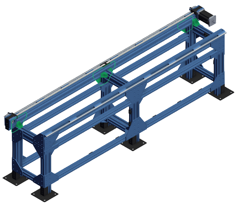
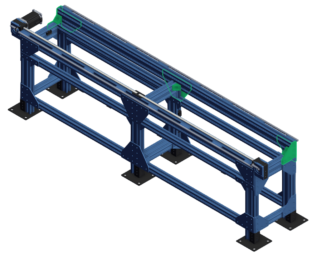
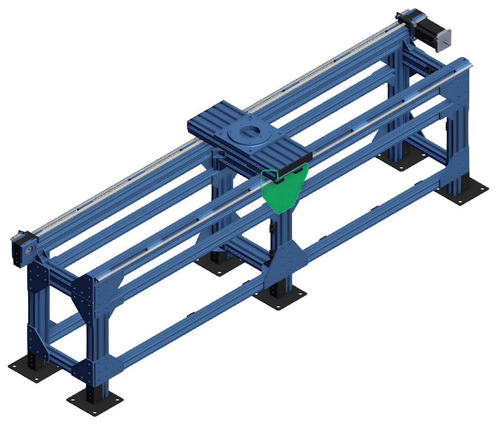
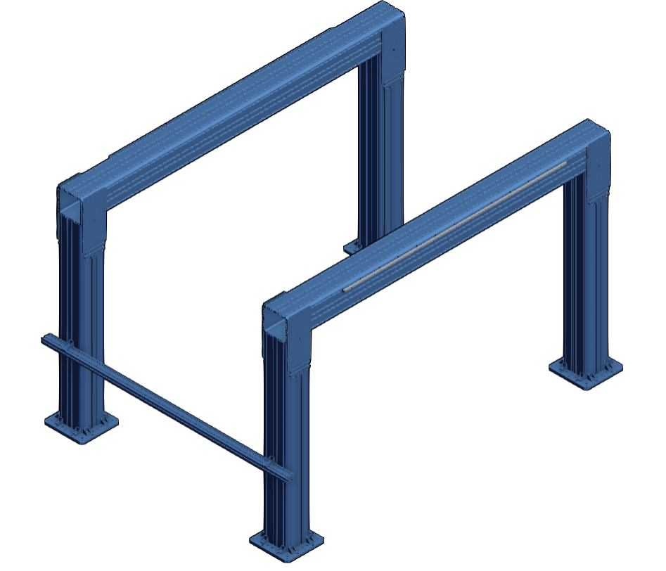
MO-LM-049-XXXX Mounted on ST-EXT-011-XXXX (XL Extrusions)
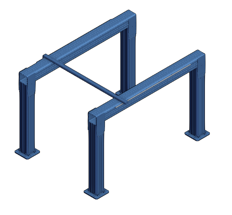
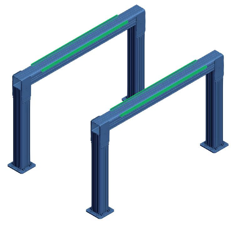
This section outlines the assembly instructions and alignment procedure for a large gantry structure made of XL (247.5 mm) extrusions, 20mm profile guide rails, and linear bearings.
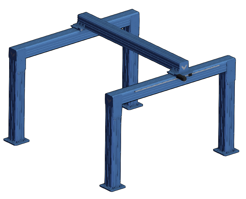
Two Guide Rail System
Tools and Parts Needed for Alignment Procedure:
Here is a list of some tools and parts needed for doing the alignment procedure:
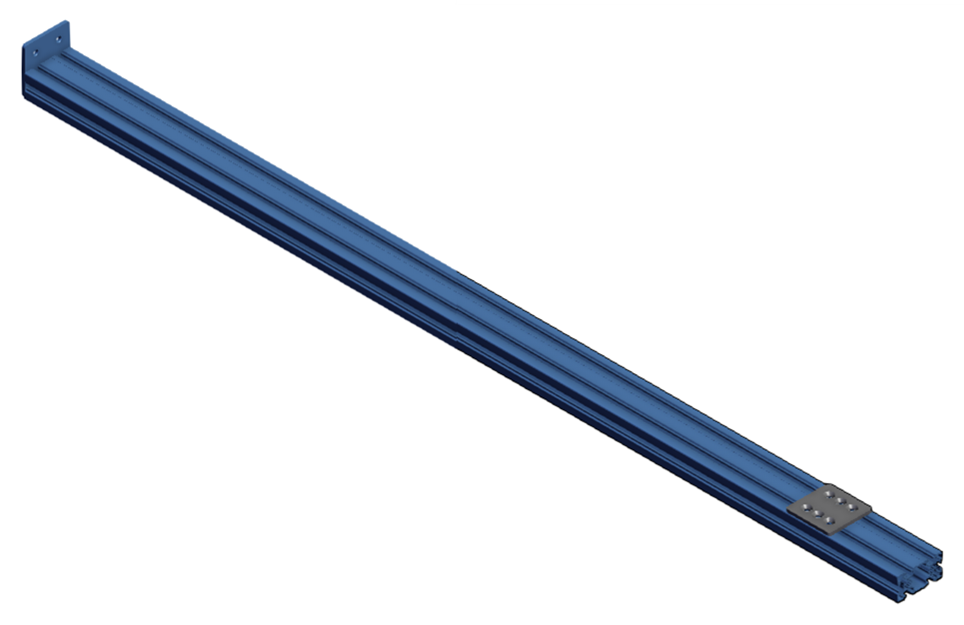
- A long enough 45x90 mm extrusion to build the alignment tool (length: rail surface-to-rail surface distance + 90 mm)
- Two 45x90 mm gussets (ST-GP-003-0005)
- One 2x2 assembly plate (ST-GP-001-0003)
- One steel plate for the dial indicator (HW-TL-013-0001)
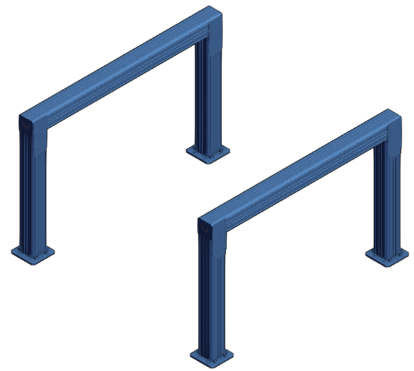
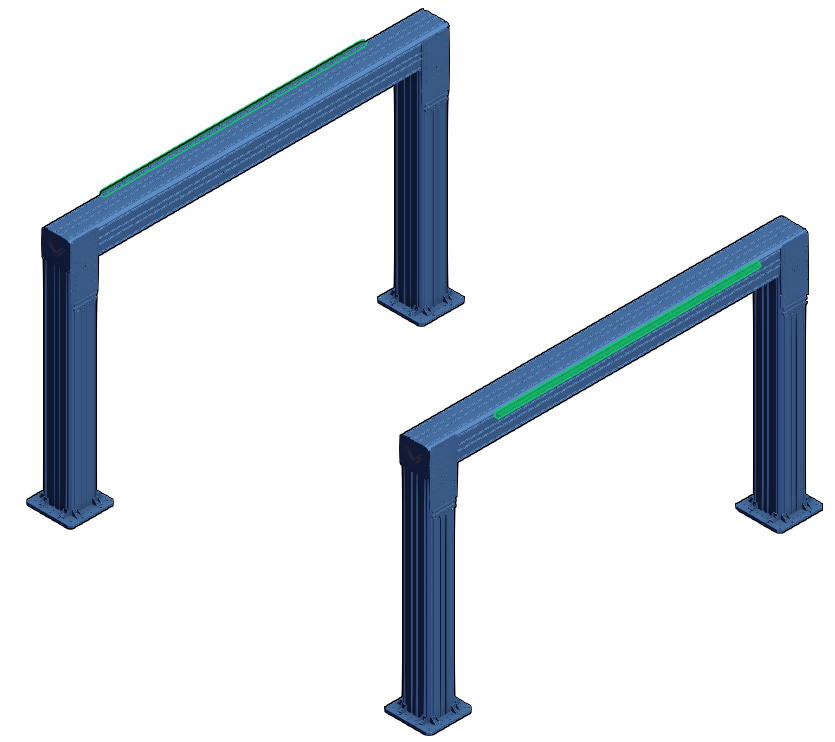
This set of instructions is intended for assemblies where there is one guiding rail installed on each half of the frame. It assumes that the first frame has been built, leveled, and anchored based on the Assembly Instructions and Installation Procedure section of 247.5 mm Extrusion Ecosystem Tech Doc.
1. The floating frame also needs to be built exactly like the previous, as per the 247.5 mm Extrusion Ecosystem Tech doc but it must not be anchored at this step. Try to build the floating frame at the approximate location of its final installation to avoid needing to move it.
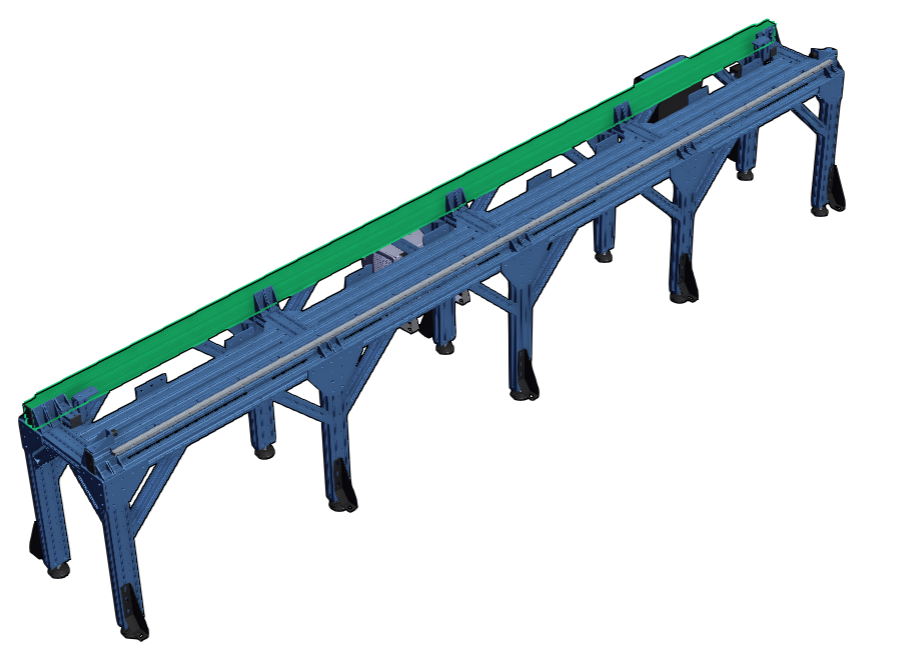
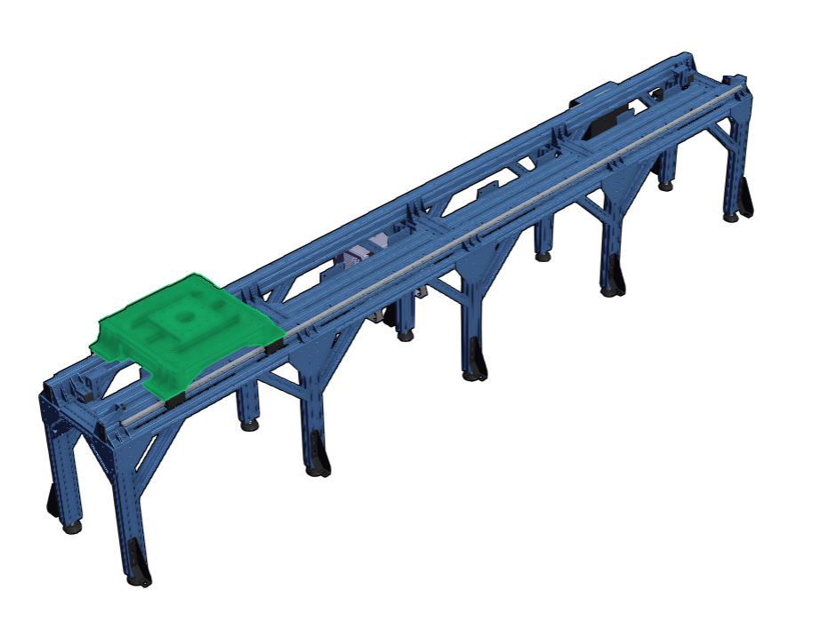
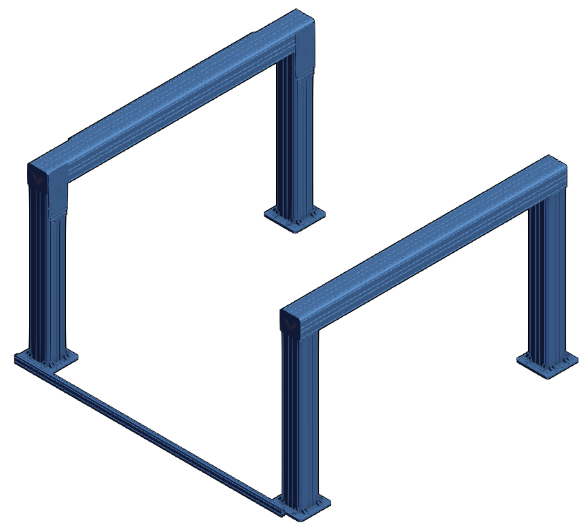
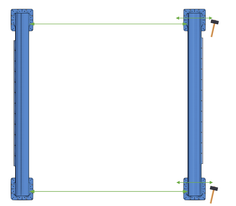
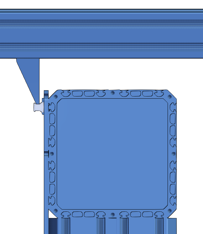
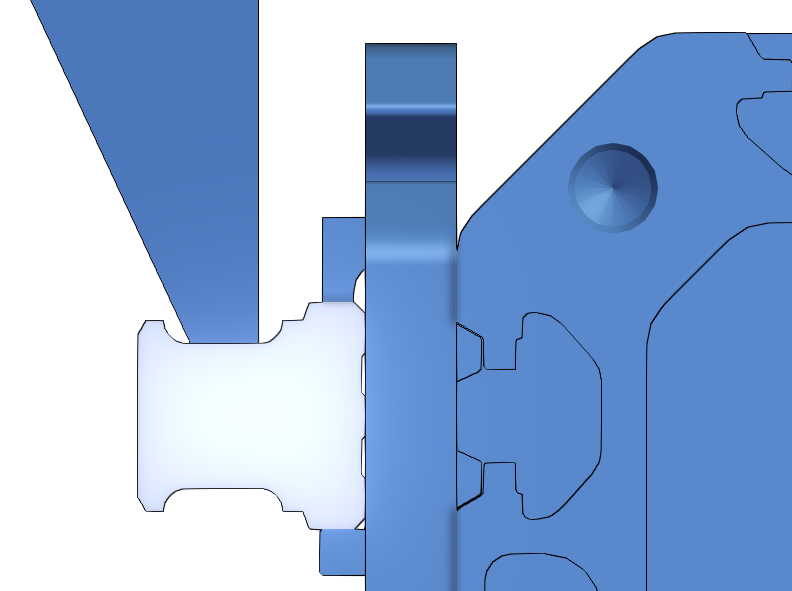
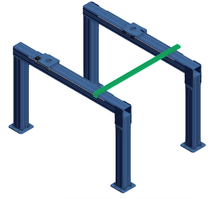
2. Make sure the base plate of the first frame is aligned with the base plate of the floating frame. A long enough 45x90 mm (Item 1 in Tools and Parts needed for Alignment Procedure) can be used. Place it on the side of the first fixed frame base plate and then a straight line can be drawn on the ground to determine the end position of the base plate of the floating frame like the picture below. You may need 2 people to do this. Use a mallet to for fine adjustment.
Note: A laser level or chalk line also can be used to align the base plate edges if you have access to one (optional).
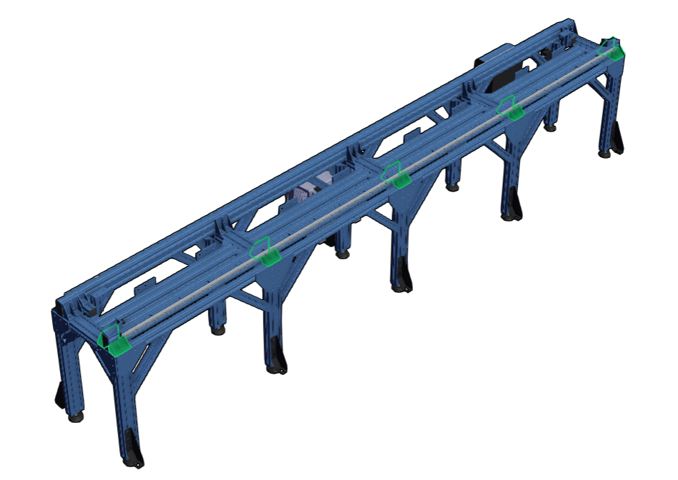
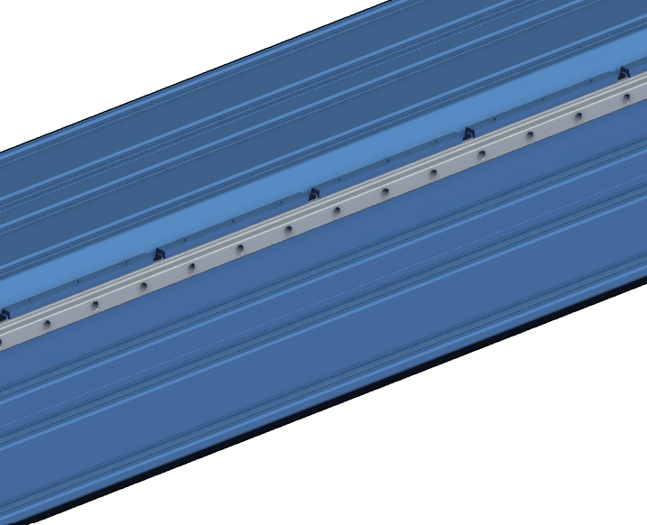
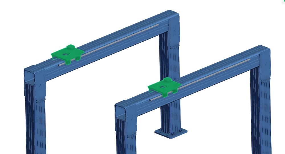
3. Install 20mm Profile Guide Rail Assembly (MO-LM-049-XXXX) on the XL extrusions. Rail mounting is to be done according to the Rail Mounts section in 20 mm Profile Guide Rails.
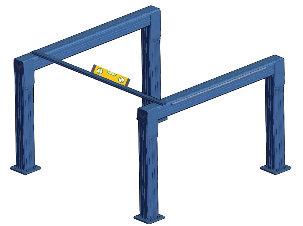
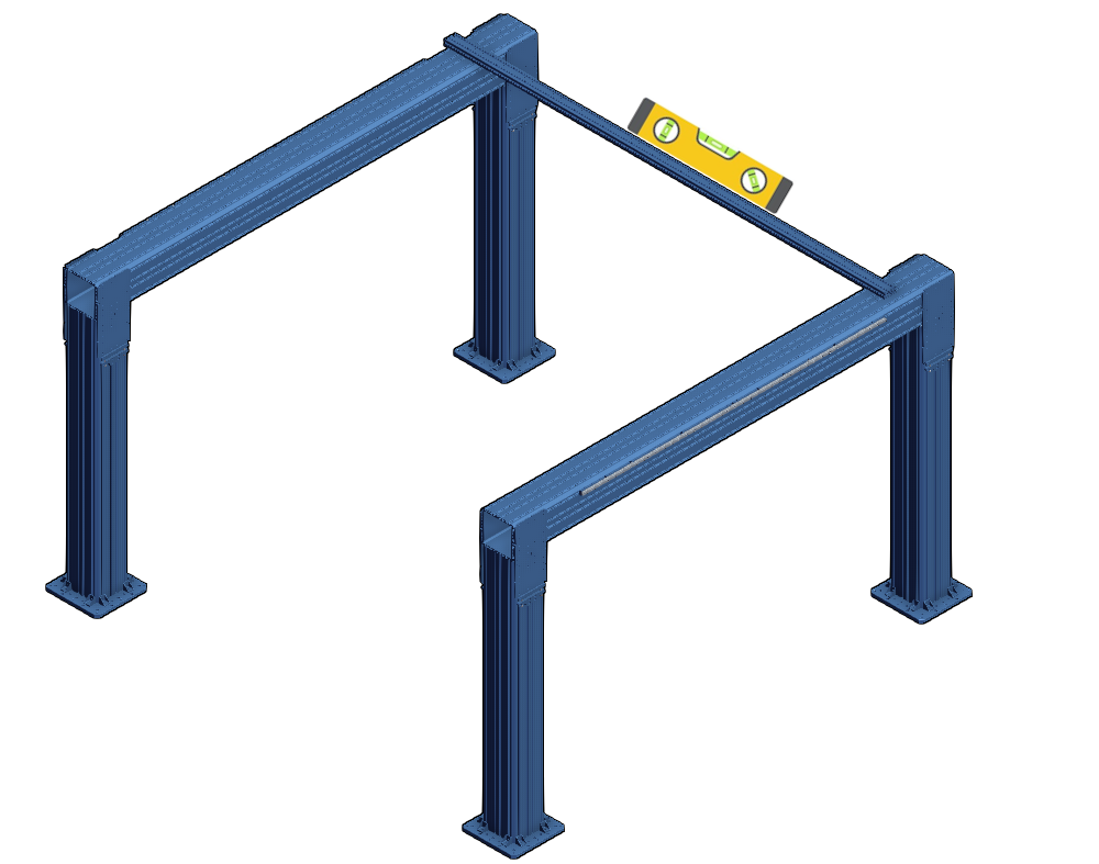
4. Align the height of the two frames by placing a long extrusion (Item 1 in Tools and Parts needed for Alignment) between the two frames on top of horizontal XL extrusions by using a construction level. If it’s not level, use the XL extrusions Leveling fixtures (ST-SP-016-0001) to adjust the height of horizontal XL extrusions. Do this for the other end of the structure too. Check level between the frames as well as along the frames.
Note: This step is an approximate height leveling. A precise height leveling will be done in the last steps for these instructions.
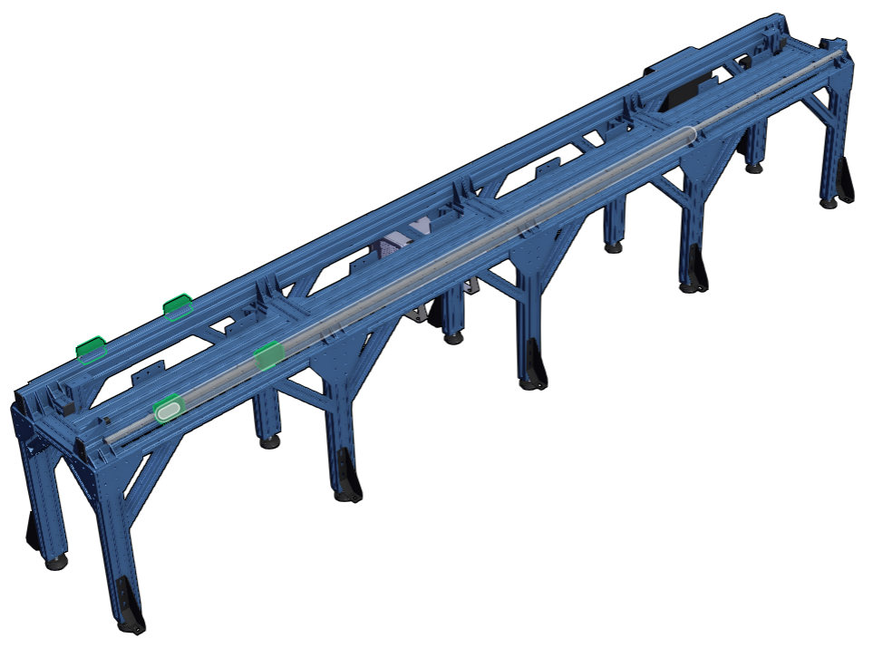
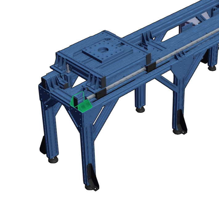
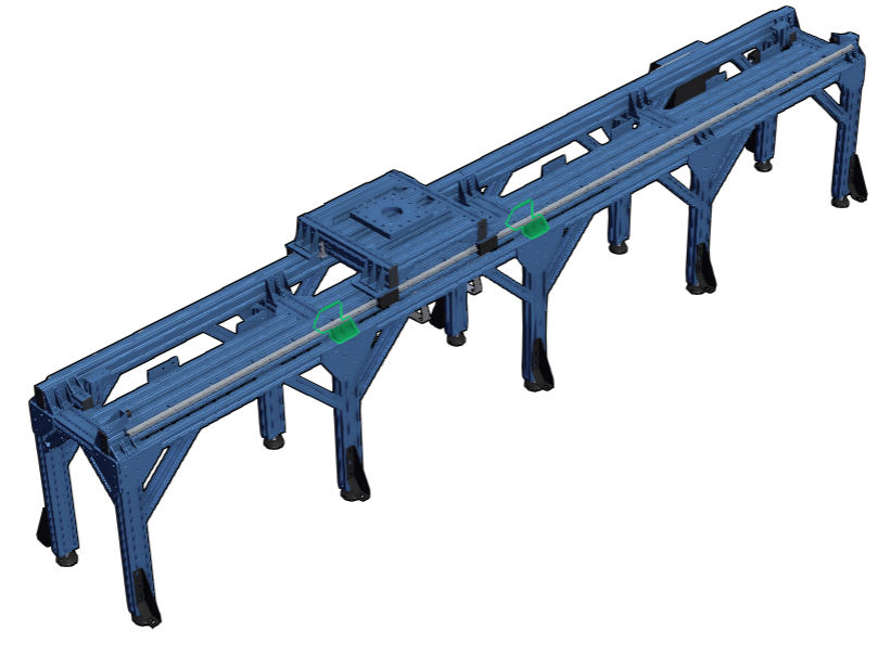
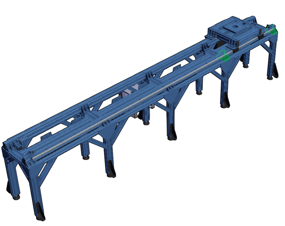
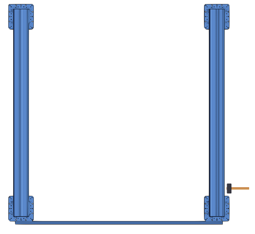
5. In this step, we need to make sure that the two frames are parallel. To do so, use a measuring tape and check the frame-to-frame distance at the beginning and the end of the frame. You can place your measuring tape tip at the back of the Assembly Plate (ST-GP-001-0027) on the fixed frame and read the distance to the back of the other assembly plate on the floating frame. If the two distances are not equal to each other and the value in the design, hammer the base plate of the columns slightly to move the whole frame precisely in the right direction. Recheck the two dimensions again to make sure these two distances are equal.
Note: Use a plastic or rubber mallet to prevent damage to the aluminum base plates. This is an approximate distance alignment, and we will do a precise distance alignment in the last steps for the rails.
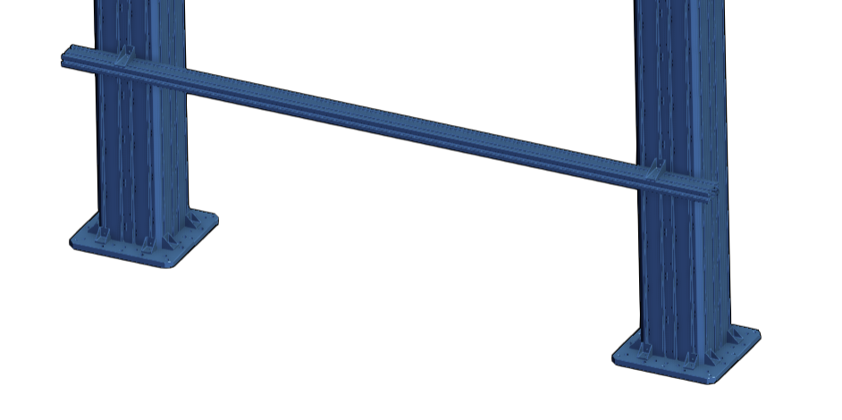
6. In this step, we need to start anchoring the floating frame. Start at either column of the floating frame. Optionally, you can install the 45x90 mm extrusion (Item 1 in Vention Tools needed for Alignment) by using the two 45x90 mm gussets (Item 2 Vention Parts needed for Alignment) on the outside of the columns. This keeps the first column fixed during drilling and anchoring.
7. Start drilling the holes for anchor bolts. You must recheck the alignment in Step 5 to make sure the frames are still parallel and don’t move during drilling. Slightly tighten the anchor bolts nuts then do this step again for the other end of the structure. Shim the floor anchor if the floor is uneven or the column is not level using shims from the Slotted Shim Kit.
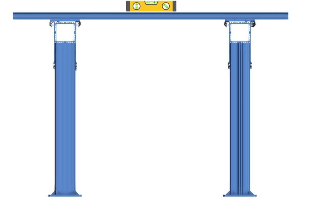
8. Assemble a tool for precise rail height leveling out of the 45x90 mm extrusion and two 45x90 mm gussets (Items 1 & 2 in Vention Tools needed for Alignment).
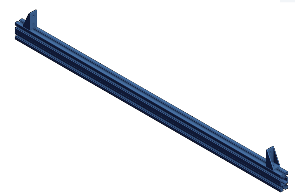
9. Place the assembled tool on top of the rails. Place the precise machinist level on top of the tool. If it is not level, use the leveling fixture (ST-SP-016-0001) to correct it. Check this on both ends of the assembly to adjust the heights and level them. Do not forget to loosen the column side screws of the assembly plates before using the leveling fixture.

Note: make sure the above gussets are placed on the straight edge of the rail, not the curved edge.
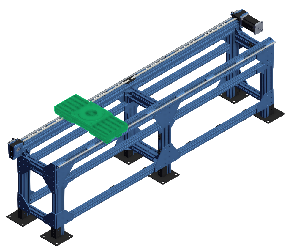
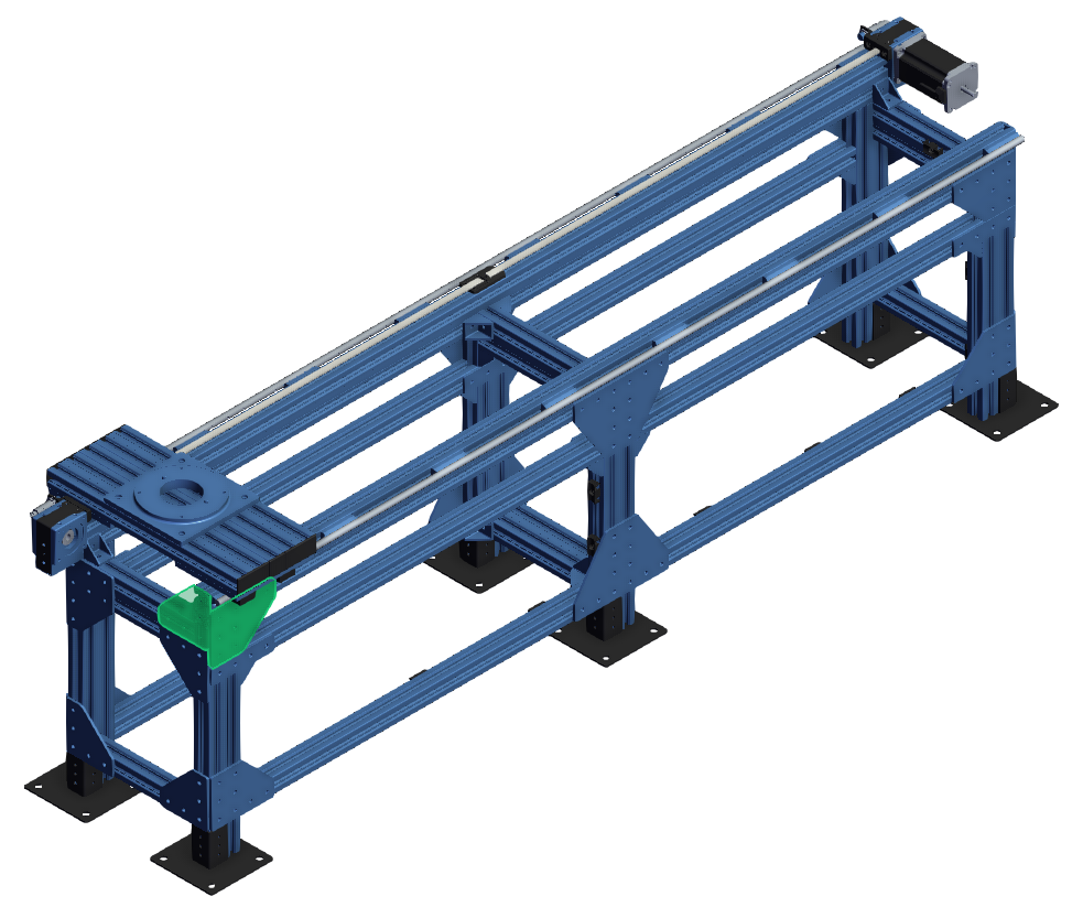
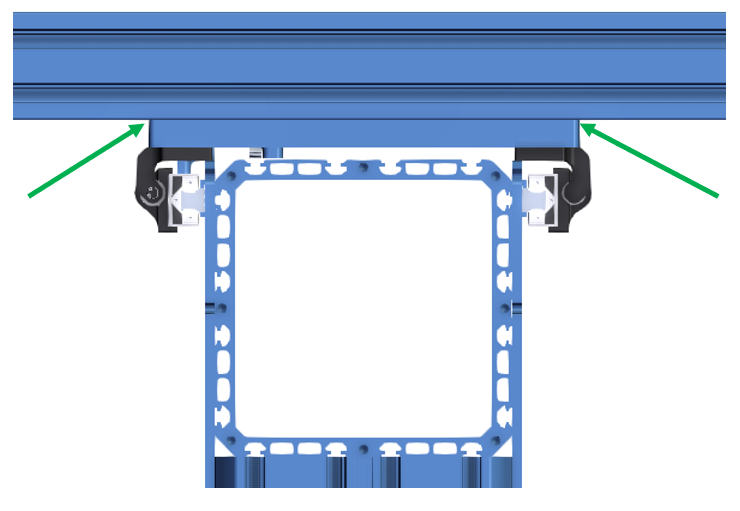
10. Modify the previously made assembly tool by adding a 2 x 2 assembly plate and the steel plate (Items 3 & 5 in list of Vention tools needed for Alignment). Install the 2 x 2 assembly plate at one end of the 45 x 90 mm extrusion as the fixed jaw of the tool and attach the dial indicator magnet base to the steel plate as the moving jaw.
11. Place the tool on top of both horizontal XL extrusions. Let the fixed jaw touch the surface of the rail at one side. Move the moving jaw (steel plate) with the dial attached along the tool body to touch the surface of the other rail on the other side of the structure. After that move it in more (approximately 5 mm) to make sure the dial indicator has enough engagement with the rail surface. Then fix the movable jaw (steel plate).
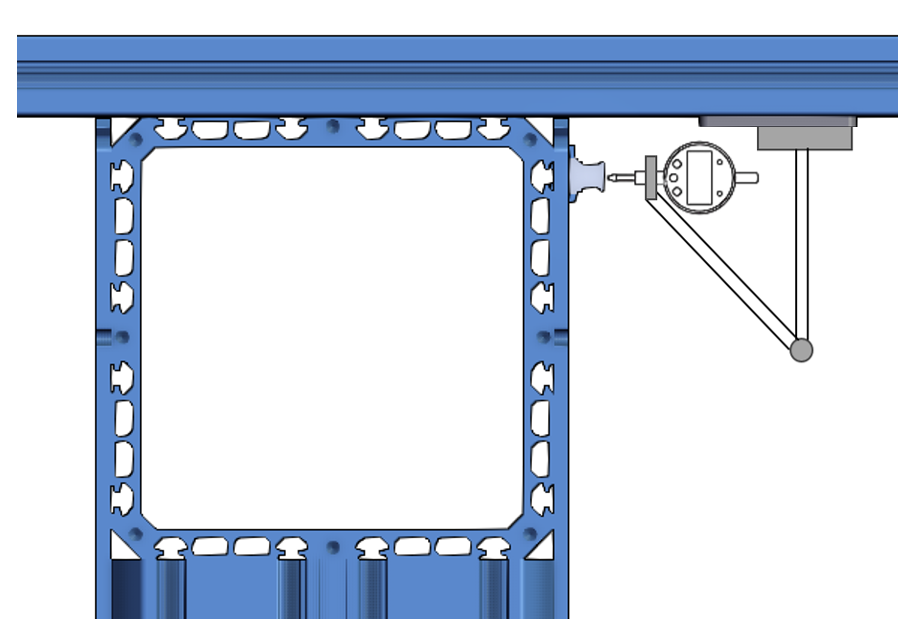
12. Starting at one end of the assembly, move the dial indicator along the rail, checking the dial indicator to find the maximum distance. When you find it, zero the dial indicator. This is the point the two frames are farthest apart.
13. Move the tool along the axis repeating Step 12, except do not re-zero the indicator. Instead, track the deviation between the fixed and floating frames. The dial number shows the total misalignment between the two rails on the structure
14. Repeat Step 13 for the entire length of the rail. If the max deviation between rails is more than 0.5mm, loosen the bolts of the column that is out of alignment and tap it with a mallet to bring the deviation within 0.5mm. Once the point of highest misalignment is less than 0.5 fully torque all of the floor anchors to lock the floating frame in place.
15. Perform the same process as Steps 12 and 13, however instead of compensating for misalignment by shifting the floating frame itself, shims will be used. The deviation shown by the dial is equivalent to the shim thickness you need to install at that location. Use small shims (MO-BR-012-0001) as per the Shimming section in 20 mm Profile Guide Rails.
16. Once complete, the dial should be able to be swept across the entire length of the axis and both the position deviation measured by the dial must be less than 0.05mm. Additionally the structure should be level along the entire length of the axis.
If Step 16 is satisfied, the special instructions for rail alignment are complete and you can resume standard assembly process.
Four Guide Rail System
Tools and Parts Needed for Alignment Procedure:
Here is a list of some tools and parts needed for doing the alignment procedure:
- A long enough 45x90 mm extrusion building the alignment tool (length: rail surface-to-rail surface distance + 90 mm)
- One 2x2 assembly plate (ST-GP-001-0003)
- One steel plate for the dial indicator (HW-TL-013-0001)
This set of instructions is intended for XL extrusion frames where each half of the frame has two guiding rails for a total of four guiding rails. It is assumed that the first frame has been built, leveled, and anchored based on the Assembly Instructions and Installation Procedure section of 247.5 mm Extrusion Ecosystem Tech Doc.
1. The floating frame also needs to be built exactly like the previous, as per the 247.5 mm Extrusion Ecosystem Tech doc but it must not be anchored at this step. Try to build the floating frame at the approximate location of its final installation to avoid needing to move a heavy frame.
2. Make sure the base plate of the first frame is aligned with the base plate of the floating frame. A long enough 45x90 mm (Item 1 in Tools and Parts needed for Alignment Procedure) can be used on the side of the first fixed frame base plate and then a straight line can be drawn on the ground to determine the end position of the base plate of the floating frame like the picture below. You may need 2 people to do this. Use a mallet to for fine adjustment.
Note: A laser level or chalk line also can be used to align the base plate edges if you have access to one (optional)
3. Align the height of the 2 frames by placing the long 45x90 extrusion (Item 1 in Tools and Parts needed for Alignment) between the two extrusions. If it’s not level, use the XL extrusions Leveling fixtures (ST-SP-016-0001) to adjust the height of horizontal XL extrusions. Do this for the other end of the structure too. Check level between the frames as well as along the frames.
Note: This step is an approximate height leveling. A precise height leveling will be done in the last steps for these instructions.
4. In this step, we need to make sure that the 2 frames are parallel. To do so, use a measuring tape and check the frame-to-frame distance at the beginning and the end of the frame. You can place your measuring tape tip at the back of the Assembly Plate (ST-GP-001-0027) on the fixed frame and read the distance to the back of the other assembly plate on the floating frame. If the 2 distances are not equal to each other and the value in the design, hammer the base plate of the columns slightly to move the whole frame precisely in the right direction. Recheck the 2 dimensions again and again to make sure these 2 distances are equal.
Note: Use a plastic or rubber mallet to prevent damage to the aluminum base plates. This is an approximate distance alignment, and we will do a precise distance alignment in the last steps for the rails.
5. In this step, we need to start anchoring the floating frame. Start at a column at either end of the floating frame. Start drilling the holes for anchor bolts. You must recheck the alignment in Step 4 to make sure the frames are still parallel and don’t move during drilling. Slightly tighten the anchor bolts nuts then do this step again for the other end of the structure. Shim the floor anchor if the floor is uneven or not level using shims from the Slotted Shim Kit.
6. Install 20mm Profile Guide Rail Assemblies (MO-LM-049-XXXX) on the XL extrusions. Rail mounting is to be done according to the Rail Mounts section in 20 mm Profile Guide Rails.
7. Install the bearings and gantries on both the fixed and floating structures as per the assembly instructions in the technical document for 20 mm Profile Guide Rails.
8. Place the long 45x90 extrusion you used in Step 3 on top of the gantry plates. Place the precise (machinist) level on top of the tool. If it is not level, use the leveling fixture (ST-SP-016-0001) to correct it. Check this on both ends of the assembly to adjust the heights and level them. Do not forget to loosen the column side screws of the assembly plates before using the leveling fixture.
Note: The assembly must be level and there must be no gaps greater than 0.125mm between the 45x90 extrusion and either gantry plate surface. This step ensures that the gantry plates are in the same plane.
9. Add the 2x2 assembly plate and the steel plate (items number 2 & 3 in list of Vention tools needed for Alignment) to the 45x90mm extrusion. Install the 2x2 assembly plate at one end of the 45x90 mm extrusion as the fixed jaw of the tool and attach the dial indicator magnet base to the steel plate as the moving jaw.
10. Place the tool on top of both horizontal XL extrusions. Let the fixed jaw touch the surface of the rail at one side. Move the moving jaw (steel plate) with the dial attached along the tool body to touch the surface of the other rail on the other side of the structure. After that move it in more (approximately 5 mm) to make sure the dial indicator has enough engagement with the rail surface. Then fix the movable jaw (steel plate).
11. Starting at one end of the assembly, move the dial indicator along the rail, checking the dial indicator to find the maximum distance. When you find it, zero the dial indicator. This is the point the two frames are farthest apart.
12. Move the tool along the axis repeating Step 11, except do not re-zero the indicator. Instead, track the deviation between the fixed and floating frames. The dial number shows the total misalignment between the two rails on the structure.
13. Repeat Step 12 for the entire length of the rail. If the max deviation between rails is more than 0.5mm, loosen the bolts of the column that is out of alignment and tap it with a mallet to bring the deviation within 0.5mm. Once the alignment is within that requirement, fully torque all of the floor anchors to lock the floating frame in place.
14. Perform the same process as Steps 12, however instead of compensating for misalignment by shifting the floating frame itself, shims will be used. First check the alignment between rail #1 and rail #4. The deviation shown by the dial is equivalent to the shim thickness you need to install at that location. Use small shims (MO-BR-012-0001) as per the Shimming section in 20 mm Profile Guide Rails. Note the alignment must be within 0.05mm once the shimming is complete.
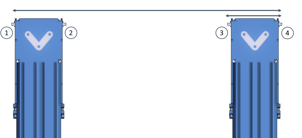
15. Check the alignment between rail #3 and rail #4 since their alignment may have been altered in step 14. Their alignment must respect the installation requirements in the Shimming section in 20 mm Profile Guide Rails.
16. Once complete the dial should be able to be swept across the entire length of the axis and both the position deviation measured by the dial must be less than 0.05mm. Additionally the structure should be level along the entire length of the axis.
If Step 16 is satisfied, the special instructions for rail alignment are complete and you can resume standard assembly process.
Step 3: Lubrication
To ensure a long-lasting system, follow the steps in the Vention Maintenance Guide.