Power Switch Module User Manual
Contents
- Overview
- Features
- Included in the box
- WARNING: Important steps to avoid electric shock
- WARNING: Hot surface
- Choosing the appropriate output connector
- Physical Interface
- Applications
- Address configuration switches
- Connecting a device to the OUT2 port
- Configuring the Power-Switch Module in Control Center
- Programming the Power-Switch Module with MachineLogic
- Using the Power-Switch Module with the Python API
Overview
The Power Switch Module (CE-MD-005-0000) extends MachineMotion 2’s functionality with an integrated solid-state relay, which lets you switch various AC-powered devices on and off.
This plug-and-play module requires just three connections: one to the MachineMotion 2 controller, one to an AC power outlet, and one to the device to control.
Compatible modules, including the Power Switch Module (CE-MD-004-0000), can also be daisy chained one after the other, making it possible to connect up to eight modules per MachineMotion 2 controller.
Features
● Switch AC loads up to 15 A at 120 VAC or 10 A at 230 VAC.
● Support various loads with two types of output connectors: one NEMA 5-15R, and one, terminal block.
● Connect compatible modules via daisy chain.
● Configurable address.
● Plug-and-play to access from the Control Center, MachineLogic and Python API.
Included in the box
| Part Number | Description | Quantity |
|---|---|---|
| CE-MD-005-0000 | Power Switch module | 1 |
| CE-CA-022-5000 | Control Device Extension Cable, 5m | 1 |
| CE-JP-001-0001 | Module Termination Jumper | 1 |
| CE-CA-001-0001 | IEC C13 Cable, CA/US, 120 V, 3m | 1 |
| CE-CA-001-0002 | IEC C13 Cable, EU, 230 V, 2.5m | 1 |
| HW-FN-003-0018 | M8 x 18-mm Screw | 2 |
| HW-FN-002-0001 | M8 Drop-in Spring-Loaded T-Nut | 2 |
WARNING: Important steps to avoid electric shock
The Power Switch Module operates at potentially life-threatening voltage levels. To prevent the risks of electric shock that could lead to serious injuries, follow the safety instructions below.
● When setting up the Power Switch Module connections, connect the input POWER cable to the AC power outlet last. Connecting to the power outlet should always be your final step.
● If you’re not using the OUT2 port, make sure the detachable plug stays mated to the fixed module connector, to prevent an exposed lead with potential live power. This is important because the OUT1 and OUT2 ports act in parallel, meaning they are either both energized or both de-energized at the same time.
WARNING: Hot surface
The top aluminum enclosure of the Power Switch Module acts as a heatsink for the internal relay. The higher the current going through the module, the hotter the surface will become. Keep this in mind when driving large loads with the module. Maximum enclosure temperature rise from ambient is specified in the datasheet.
Choosing the appropriate output connector
The Power Switch Module has two parallel output connectors.
- Only use the OUT1 port with a standard NEMA 5-15P connector, and if the load operates at a max voltage of 125 VAC with a max current of 15 A.
- The OUT1 port is a standard NEMA 5-15R connector, compatible with 120 VAC devices for North America and capable of delivering up to 15 A.
- Use the OUT2 port with any other connector (not NEMA 5-15P), and/or if the load has an operating voltage higher than 125 VAC.
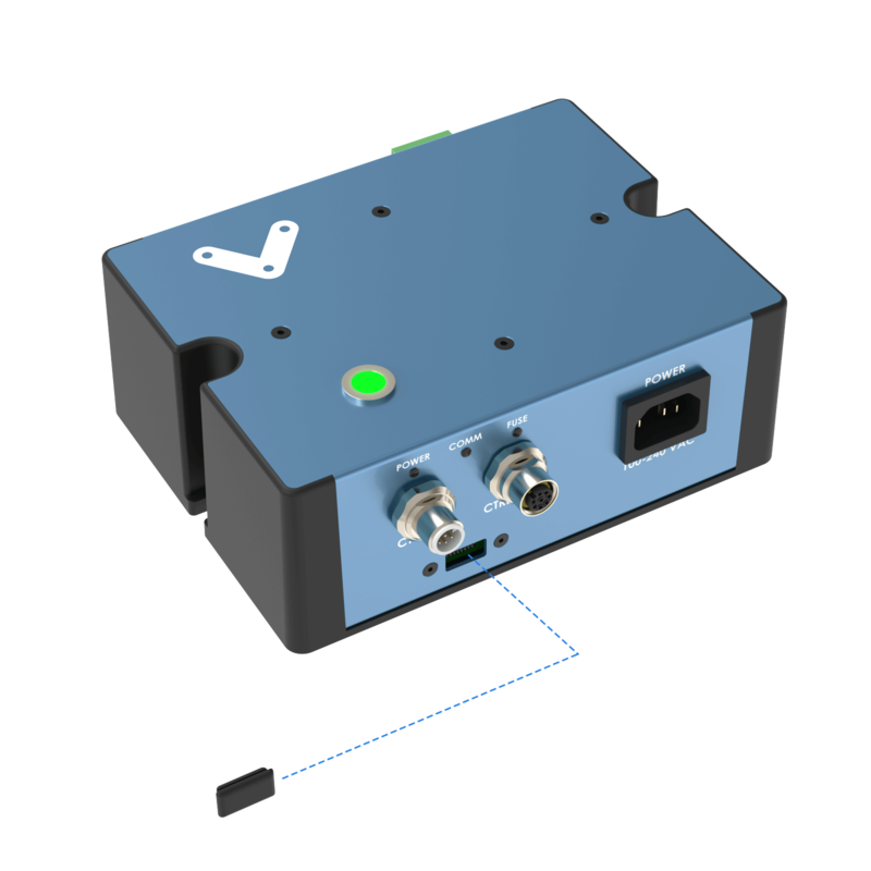
- The OUT2 port is a two-part terminal block connector mating. The male connector is a fixed part (jack) of the module, whereas the female connector is detachable (plug) and provides three screw connections for flying leads (live, neutral, and earth).
Physical Interface
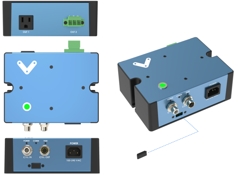
LED status indicators
| Name | LED Color | Indicates (when ON) |
|---|---|---|
| SWITCH STATUS | Green | Power switch closed (active) |
| POWER | White | 24 VDC supplied to module |
| COMM | Yellow and Blue | RS-485 communication functional |
| FUSE | Red | Module internal fuse tripped |
Applications
Connecting to MachineMotion 2 (direct connection)
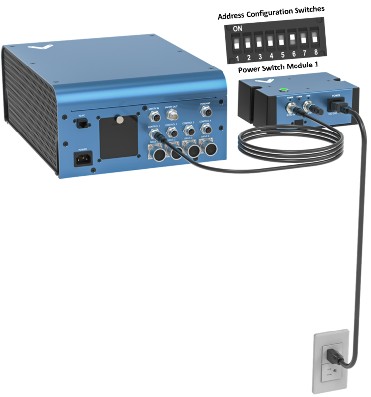
To connect the Power Switch Module directly to a MachineMotion 2 controller (see Figure 2):
- Set the Power Switch Module address, as explained in the Address configuration switches section.
- Using the Control Device Extension Cable (CE-CA-022-5000):
- Connect the male end to any CONTROL port on the MachineMotion 2 controller.
- Connect the female end to the CTRL IN port on the Power Switch Module.
- Connect the Module Termination Jumper (CE-JP-001-0001), to the CTRL OUT port on the Power Switch Module.
- Connect the AC-powered device to be controlled to one of the Power Switch Module output ports; either OUT1 (US/Canada, NEMA 5-15R) or OUT2 (Terminal Block with Screw Connections).
- Using an appropriate IEC C13 cable (CE-CA-001-0001, CE-CA-001-0002, or other):
- Connect the female end to the POWER port on the Power Switch Module.
- Connect the male end to an AC power outlet.
Connecting compatible modules (daisy chain)
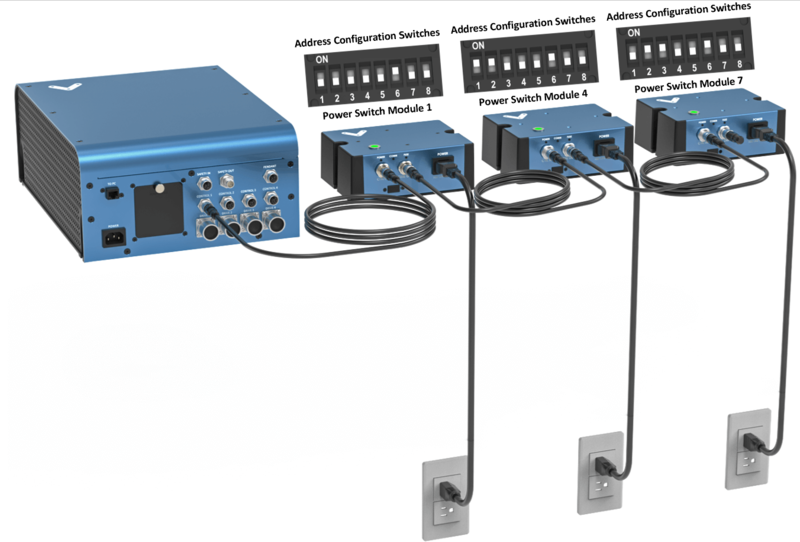
Compatible modules, including the Power Switch Module, can also be daisy chained to a single CONTROL port on the MachineMotion 2 controller (see Figure 2). Across all four CONTROL ports, the controller supports up to eight modules at the same time, provided they all have distinct addresses (see Address configuration switches).
To connect several modules in a daisy chain:
- Set a distinct address for every module of the daisy chain, as explained in the Address configuration switches section.
- Using a Control Device Extension Cable (CE-CA-022-5000):
- Connect the male end to any CONTROL port on MachineMotion 2.
- Connect the female end to the CTRL IN port on the first module in the daisy chain.
- For every additional module to be connected, repeat this step using an additional Control Device Extension Cable:
- Connect the male end to the CTRL OUT port on the previous module in the daisy chain.
- Connect the female end to the CTRL IN port on the current module in the daisy chain.
- Connect the Module Termination Jumper (CE-JP-001-0001) to the CTRL OUT port on the last module in the daisy chain.
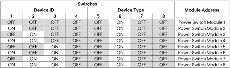
Address configuration switches
Each module has an address with two components: device ID and device type. Both device ID and device type are set by changing the state of the address configuration switches, which are located at the front of the Power Switch Module under a removable rubber cap.
Switches 1 to 4 define the module device ID and allow the MachineMotion 2 controller to know which module it is communicating with. Every module connected to the same controller should have a distinct device ID, regardless of its device type.
Switches 5 to 8 define the module device type and their positions should remain identical for all modules of the same type.
The table below lists every valid address for the Power Switch Module. An individual switch is considered ON when the selector is slid up and OFF when the selector is slid down.
Connecting a device to the OUT2 port
The OUT2 port is a two part terminal block connector mating that can be used to control any AC-powered device within the Power Switch Module specifications (see Datasheet).
To connect a device to the OUT2 port:
- Make sure the device has two wires (black and white) or three wires (black, white, and yellow/green).
- Strip 7 mm of insulation off the device’s wires.
- Use the markings on the Power Switch Module to identify the live (L), neutral (N) and ground (⏚) terminals.
- Remove the plug from the OUT2 port.
- Insert and screw the black wire into the OUT2 plug L (live) terminal.
- Insert and screw the white wire into the OUT2 plug N (neutral) terminal.
- If available, insert and screw the yellow/green wire into the OUT2 plug ⏚ (ground) terminal.
- Re-insert the plug from step 4 in the OUT2 port.
Configuring the Power-Switch Module in Control Center
If you would like to configure your power-switch module and utilize MachineLogic to program your power-switch, follow the steps below:
- Open the Control Center on a PC (by entering 192.168.7.2 in the Google Chrome URL) or use the MachineMotion 2 Pendant.
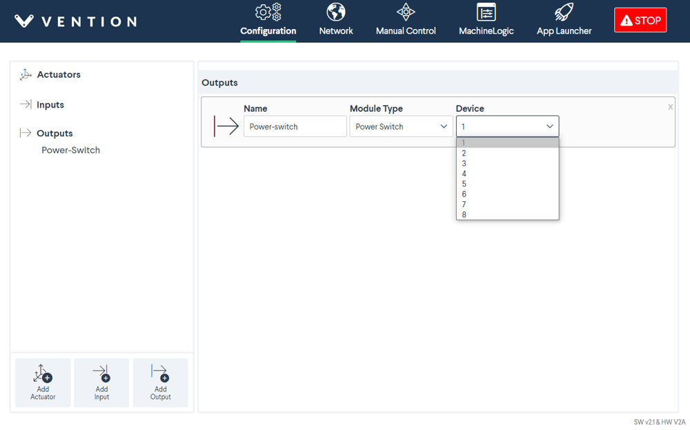
- Go to the Configuration tab and click Add Output.
- Fill out the following fields:
- Name: Give your push-button a friendly name, which will be used to call the push button module in MachineLogic
- Module Type: In the drop-down menu, select Power Switch
- Device: Represents the device ID of your module. The device number is configured on the physical module using dip-switches, therefore, ensure the device ID configured in this dropdown matches the dip switches configured on the physical device.
- To test the configured push-buttons, go to the Manual Control tab and navigate to the Digital Inputs/Outputs at the bottom left of the screen.
- Under Outputs, you should see your configured power-switch modules:
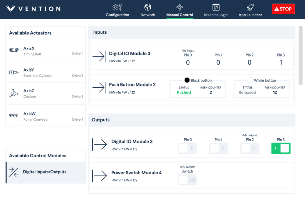
You could test the configured power-switch module by clicking the toggle OFF/ON to check if the device connected to the power-switch toggles on and off.
Programming the Power-Switch Module with MachineLogic
To program your power-switch in MachineLogic, ensure you have completed the steps in Configuring the Power-Switch Module in Control Center.
- Go to the MachineLogic tab.
- Click Add command > Add Outputs:
- Under Output, select the Power Switchfrom the drop-down menu. Select the friendly name of your power switch under Output Name and select if you would like to turn your power-switch On or Off
Using the Power-Switch Module with the Python API
See Python API reference here