AC Motor and VFD for Material Handling
Contents
AC Motor and VFD Guide
This guide covers commissioning and setup of the AC motor and VFD kit. This kit is a lower-cost alternative to our stepper drives for powering your material-handling operations.
The VFD (variable frequency drive) powers a 1/2HP three-phase AC motor, which is paired to a 3:1 gearbox, with Vention’s standard NEMA 34 output. It comes pre-wired for mains power, motor power, and three MachineMotion digital input connections.
Tech specs: Motor and VFD
| Specification | Value |
|---|---|
| Compatible conveyor mounts | MO-CV-003-0001, MO-CV-009-0001, MO-CV-016-XXXX |
| Max power | 1/2 HP (0.37kW) |
| Motor speed range | 431.25 RPM @ 15 Hz to 1725 RPM @ 60Hz |
| Motor output torque | 5.5 Nm* |
| Gearbox reduction ratio options | 3:1, 8:1, 10:1, 15:1 |
| Max conveyor speed | HD: 1200, O-ring: 1500, Belt: 700 (mm/s) |
| Motor input voltage | 230 V |
| Motor cooling method | Air-cooled with fan |
| Gearbox input flange | NEMA 56-C |
| Gearbox output flange | NEMA 34 |
| VFD input voltage | 120 V (North America), 240 V (Europe) |
| VFD IP rating | IP31 |
| Control type | Manual / MachineMotion |
| Combined weight | 12.5 kg |
| Certifications | Motor: CE, CSA; VFD: CE, UL, CSA, EAC, RoHS2, IE2 |
*Measured at motor breakdown torque
Safety
Important: Take the following safety precautions when doing any maintenance:
- Never work on energized equipment.
- Always establish the motor connection first before energizing the VFD.
- Routinely inspect the motor and gearbox to ensure all bolts are tightened properly.
Mounting the motor
The motor-gearbox combination come pre-assembled.
To mount the motor:
- Rotate the conveyor rollers, by hand, to align the drive input keyway with the gearbox output shaft’s orientation.
- Apply a small amount of grease to the gearbox output shaft so that it is lightly coated. This will reduce the possibility of fretting corrosion occurring during operation, making future removal easier.
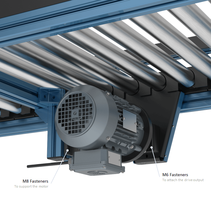
- M6 fasteners are provided to attach the gearbox to the conveyor drive input. Ensure the bolts are tightened adequately.
- M8 hex head bolts (HW-FN-103-0025), T-nuts (HW-FN-002-0001), washers (HW-WS-001-0001) and split washers (HW-WS-001-0003) are provided to support the motor mounts. This is recommended as the motor and gearbox will induce a substantial bending moment on the motor mount due to its length and mass. It must also be noted that hole pattern of the base mount does not respect Vention’s 45 mm increment standards.
Some important design considerations:
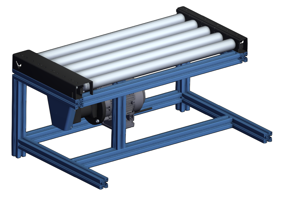
- The motor mount support must be designed in away to allow for belt tensioning, such as is required with the HD roller conveyor. For that, it is recommended to use two vertical extrusions as seen below, whereby the M8 fasteners can be loosened, tension adjusted, and then re-secured along that vertical plane.
- With an appropriate motor mount support designed, ensure that the motor power cable, which is modelled in MachineBuilder, does not intersect with the extrusions. The cable will not be able to sustain very tight bend radii, which may damage it.
- You don’t need to add 2 extrusions to support the motor mount, even adding 1 extrusion is enough. The pictures below show you some suggested designs for motor mount support designs.
Mounting the VFD
The VFD supplies the motor with power and controls its speed. MachineMotion can communicate with the VFD and control up to three digital inputs, such as the VFD start-stop function, via the digital IO module.
To mount the VFD:
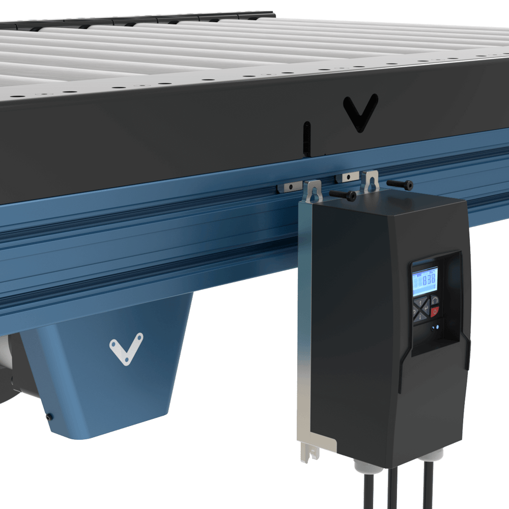
- Select the placement area. Choose a dry place, like the side of the structure supporting the conveyor. Leave 150 mm of clearance below the VFD for its electrical cables, and ensure the VFD is within reach of the 2.5 m-long motor power cable.
- Attach the VFD with the 2 provided M5 T-nuts and bolts. Insert them along the same horizontal t-slot. The fasteners are slightly long, so they can extend from the t-slot and serve as a perch to hook the VFD in to for easy access.
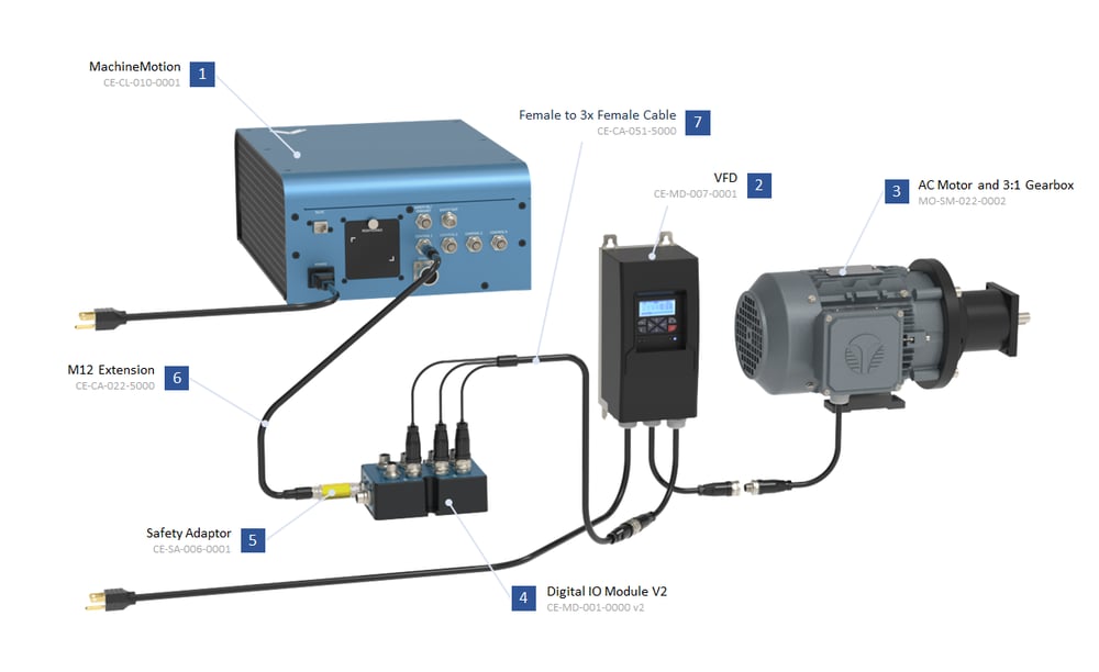
Connecting electronics
Internally, both the AC motor and VFD come pre-wired and configured for basic motor operations. To complete the electrical installation, follow the wiring diagram below:
Controlling and programming the VFD
The Lenze VFD is an extremely feature-rich frequency drive allowing for highly configurable control and motor operation. This is possible through modifying and configuring so-called parameters. Parameters are values, stored in the VFD, that control how the motor and VFD behave. Most of the parameters needed for basic function are pre-set and do not need changing.
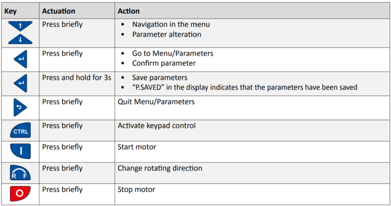
You can perform operations using the VFD keypad, as described in the table below.
However, you may need to manually configure some parameters if you are modifying motor operating characteristics or setting up certain digital inputs.
To change a parameter:
- Press Enter briefly.
- With the up and down arrow keys, select the group the parameter is in. Parameters are formatted as PXYY.ZZ, where the first digit after P indicates the group. (For example, parameter P400.01 is in group 4.) Press Enter.
- With the up and down arrow keys, select the parameter. Press Enter.
- With the up and down arrow keys, change the parameter value. Press Enter to input the change.
- To save the new parameter value, press and hold Enter for at least three seconds.
Caution: Incorrect parameters can damage the motor or VFD.
Starting and stopping the motor
You can control the motor directly from the VFD - which is the default, manual option or through MachineMotion, which requires further integration.
Enabling VFD keypad control
- Press CTRL briefly. The screen displays ”Keypad Full CTRL?” and then indicates the desired state (e.g.: “ON” will be displayed as the desired state).
- Press Enter briefly to change from OFF to ON. A red error light will begin to flash when keypad control is enabled, this is normal.
Control via VFD keypad
To control the motor directly from the VFD, press the following buttons:
- (I) key. Start motor, press briefly.
- UP and DOWN arrow keys. Change frequency (motor RPM). There is no direct RPM feedback.
- R-F key. Change directions.
- (0) key (in red). Stop motor.
Control via MachineMotion
To control the motor remotely via MachineMotion, you will need to set up remote triggering of digital inputs (such as a start-stop function). This requires a MachineMotion, the Digital IO Module (CE-MD-001-0000__2) and M12 Cable for Digital I/O Module v2 - Female to 3x Female (5m) (CE-CA-051-5000), all sold separately.
MachineMotion Software Confiuguration
The AC Motor and VFD is an actuator controlled via digital outputs and not the MachineMotion drives. Therefore there are additional setup steps to take, in order to have your VFD being stopped by the system upon an emergency stop event. It is important to note that it is NOT a safety rated actuator.
- Connect your laptop to the MachineMotion, open your Chrome browser, and navigate to the following URL : http://192.168.7.2
- Click on the “Cloud9” icon.
- In the left pane, navigate to the
vention-controlfolder and open themm-config.jsonfile. - From there, change the
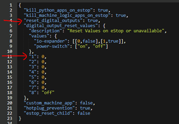
digital_output_reset_valuesflag totrue. Note: Ifreset_digital_outputsis set totrue, when the MachineMotion enters Emergency Stop, all outputs of each control module will be reset to the values defined in this list. There is one configurable value per device ID. 0 or 1 should be used for IO modules, while on or off should be used for power switch module. if an invalid value or no value is given for the device ID, all of its outputs will be reset to 0. - Then please make sure that the device number corresponding to the Digital IO Module is plugged into has a value of
0. For example, if your VFD is connected to a Digital IO Module with a device number 1, make sure that the highlighted line looks as such:
- Save the file and then reboot your MachineMotion controller to apply the changes.
VFD Configuration
The following guide will run through the example of setting up the “start-stop” and “forward-reverse” digital inputs:
- Establish the connection of the Digital I/O module to the MachineMotion via any of the four available control ports.
- Connect the triple splitter cable as follows:
- Connector labelled Red to Digital Output 0 (start-stop trigger)
- Connector labelled Blue to Digital Output 1 (reverse trigger)
- Connector labelled Green is not used
- Establish the connection with the splitter cable to the VFD as seen above.
- With the VFD keypad control enabled, navigate to parameter menu P210.00, which is the minimum motor frequency. It is natively set to 0 Hz, however will be required to be set at the desired operating frequency. Set the desired value using the UP and DOWN arrow keys and press Enter once the desired value is achieved.
- Return to the main menu and disable keypad control. Note the displayed text on the screen indicating “KSTOP”.
- Press the motor start button (I). It should now read “STOP”. You are now ready to control the VFD from MachineLogic.
- In MachineLogic, under Manual Control, enable Digital Output 0, the motor should spin up to the previously set frequency.
- With Digital Output 0 still triggered, enable Output 1, the motor should decelerate and reverse direction back up to the previously set frequency.
For a list of additional available digital inputs and a step-by-step programming guide, see Lenze’s i510 commissioning guide, section 6.2: lenze.com.
If you have any questions or concerns about configuring VFD parameters, Vention’s customer success team can assist with troubleshooting.
M12 S-Key 4 pins Female Connector
| Pin | Description |
|---|---|
| Pin 1 | Phase U |
| Pin 2 | Phase V |
| Pin 3 | Phase W |
| Pin 4 | EARTH |
M12 A-Key 5 pins Male Connector
| Pin | Description |
|---|---|
| Pin 1 | VFD Input 1 |
| Pin 2 | VFD Input 2 |
| Pin 3 | 0V |
| Pin 4 | VFD Input 3 |
| Pin 5 | Not Connected |