MachineMotion Path Following Interface
MachineMotion V2 Path Following Interface
Overview
MachineMotion’s path following interface enables Vention machines to execute 3D trajectories. It is modelled after standard CNC machine interfaces and can handle a variety of commands. To perform path following with MachineMotion, a user will need:
- MachineMotion hardware V2B3 or newer [see how to find this in Method 3 - MachineMotion Pendant Step 3]
- MachineMotion software v2.6.0 or newer [see how to find this in Method 3 - MachineMotion Pendant Step 3]
- A g-code file compatible with [Vention’s g-code interface]
- A python script that loads and starts the g-code file (see Python Example at the bottom of this page)
The Guide for the MachineApps - Path Following for MachineMotion 1, can be found in the ‘‘Documentation for Previous Releases’’ at the bottom of this page.
Path following on the MachineMotion happens in two steps: g-code parsing and motion streaming. G-code parsing is the process of turning g-code commands into 3D setpoints, while motion streaming is the act of sending those setpoints to relevant drives at a fixed period. Since g-code has a generic syntax that maps to tools and axes, while motion streaming is tied to Vention drives and I/Os, there are three main elements that need to be defined for path following: axis configuration, tool configuration and path parameters. The following sections will show you how to set up and program a MachineMotion, as well as a full description of available g-code commands.
Axis Configuration
Vention’s g-code interface support three axes: X, Y and Z. Each axis may be mapped to a drive on MachineMotion. If using synchronized drives (e.g. two timing belt actuators with gearboxes), the g-code axis must be associated with the parent drive of the Vention axis. For example, in a python script, this is how one would setup their axis configuration for a machine with a synchronized timing belt axis on drives 1 and 2 and a ballscrew axis on drive 3:
# associate with the parent drive
driveAssociation = {"X": 1, "Y": 3}
# Configure the path following mode
mm.configPathMode(driveAssociation)
The mapping between g-code axes and Vention drives is arbitrary; one could assign drive 4 to the X axis and drive 1 to the Y axis.
NOTE: It is important to consider the directions of g-code axes and their effect on the behaviour of the machine. If the machine has an end of arm tool that can collide with a workpiece, ensure that axes home away from the workpiece. And example of this is in CNC routing applications, the Z (vertical) axis should home upwards and away from the workpiece. Axis directions should also be set up to follow the right hand rule to avoid discrepancies between the expected and executed path.
Tool Configuration
G-code programs sometimes make use of one or more tools. These tools can be lasers, pneumatics, routers, etc. On Vention machines, these tools are controlled with digital outputs. Vention’s python interface enables the configuration and control of digital outputs via the DIGITAL_OUTPUT_STATE and TOOL classes:
clockwise = DIGITAL_OUTPUT_STATE(deviceId=1, port=0, value=1)
counterClockwise = DIGITAL_OUTPUT_STATE(1, 1, 1)
tool1 = TOOL(1, clockwise, counterClockwise)
# associate with the parent drive
driveAssociation = {"X": 1, "Y": 3}
# Configure the path following mode
mm.configPathMode(driveAssociation, tool1)
In Vention’s path following interface, a tool consists of a tool number as well as a configuration for clockwise and counterclockwise rotation. Each rotation configuration corresponds the digital IO module’s device ID, port and value that is wired to the desired tool. An arbitrary amount of tools can be defined via the Python API, provided each tool has a unique tool number.
Parser Configuration
Vention’s g-code parser takes only one argument as configuration: the max path acceleration. This corresponds to the maximum rate in mm/s2 at which the output path can accelerate. Below is an example of how to define the max path acceleration:
maxPathAcceleration = 1000  # mm/s^2
mm.setAxisMaxAcceleration(1,1000)
mm.setAxisMaxAcceleration(3,1000)
mm.setAxisMaxSpeed(1,500)
mm.setAxisMaxSpeed(3,500)
# Start Path Following.
mm.startPath(GCODE_STRING, maxPathAcceleration)
NOTE: The max path acceleration, as well as the path speed, is independent from and capped by each drive’s max acceleration and speed. It is good practice to set each relevant drive’s max speed and acceleration in python before entering path following mode
G-Code Interface
Vention’s g-gode interface provides a set of machine instructions that allow a user to smoothly move multiiple axes at once. There exist various different versions of g-code that are offered by industrial manufacturers. Vention’s is based off RS-274-NGC gcode language and LinuxCNC. If using a CAM software to generate g-code, choosing either as a post-processor will ensure that it is compatible with MachineMotion. Vention does not support the entire list of g-code commands provided by RS-274-NGC or LinuxCnc, so some advanced codes (such as custom drilling routines or patterns) may not be recognized. The following section describes the two types of available g-code commands: operational mode commands and movement and tool commands.
Operational Mode Commands
Operational mode commands affect the way that Vention’s g-code parser generates points. They don’t cause motion of axes or tools.
Format:
G20
Description:
Sets length units to inches. Affects distances and speeds. It is a good idea to include units in the preamble of each g-code file.
Example:
G91 G20
G0 X5 F100 ; X axis will 5 move inches at 100 inches/minute
Format:
G21
Description:
Sets length units to millimeters. Millimeters are the default length unit of the parser. Affects distances and speeds. It is a good idea to include units in the preamble of each g-code file.
Example:
G91 G21
G0 X50 F1000 ; X axis will move 50 mm at 1000 mm/minute
Format:
G61
Description:
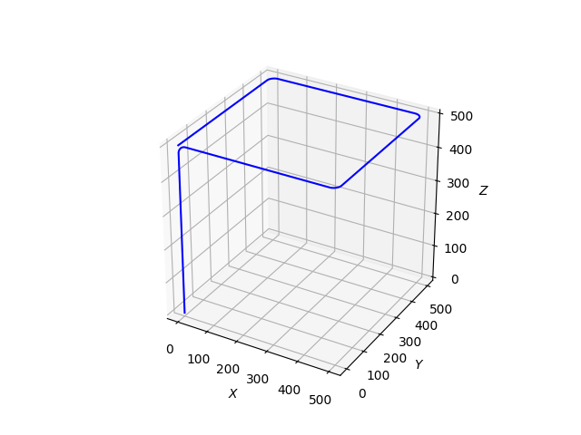
Exact path mode, movement exactly as programmed. Moves will slow or stop as needed to reach every programmed point. If two sequential moves are exactly co-linear movement will not stop.
Example:
G91 G21 G61
G0 X500
Y500
X-500
Y-500

Format:
G64 P<Tolerance>
Description:
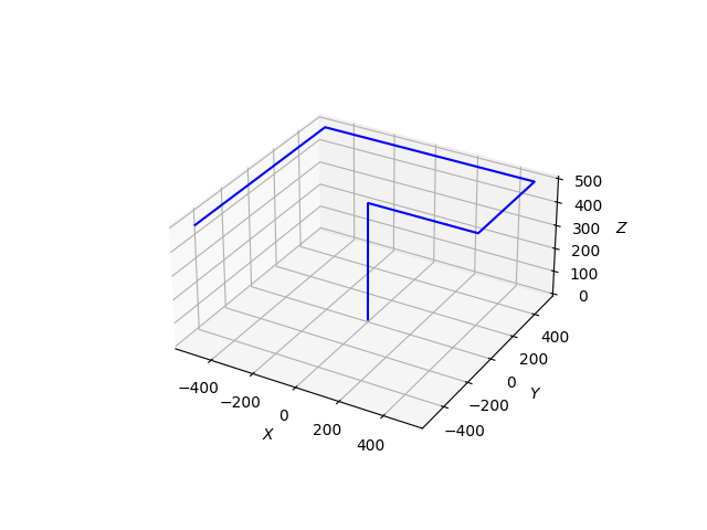
Path blend mode. The parser will blend non-colinear moves together with circular arcs to maintain velocity. This results in smoother tool motion at the expense of some precision on the path.
Arguments:
- Tolerance (float): Optional. Maximum distance in length units (see G20 and G21*)* output path can deviate from each programmed point. The velocity will be reduced if needed to maintain the path.
Example:
G91 G21 G64 P10.0
G0 X500
Y500
X-500
Y-500
Format:
G90
Description:
Axis numbers (X, Y, Z) usually represent positions in terms of the currently active coordinate system (See G0, G1 and G92).
Example:
G21 G90 G64 P1
G0 Z500
X500
Y500
X-500
Y-500
Format:
G91
Description:
In incremental distance mode, axis numbers usually represent increments from the current coordinate. (See G0, G1 and G92).
Example:
G21 G91 G64 P1
G0 Z500
X500
Y500
X-500
Y-500

Format:
G90.1
Description:
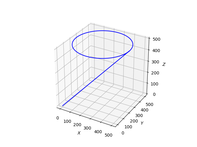
Absolute distance mode for I, J & K offsets. When G90.1 is in effect I and J both must be specified with G2/3 for the XY plane or J and K for the XZ plane. (See G2 , G3, G17, G18 and G19).
Example:
G90 G21 G61 G17 G90.1
G0 X500 Y250 Z500
G3 X0 Y250 I250 J250
G3 X500 Y250 I250 J250

Format:
G91.1
Description:
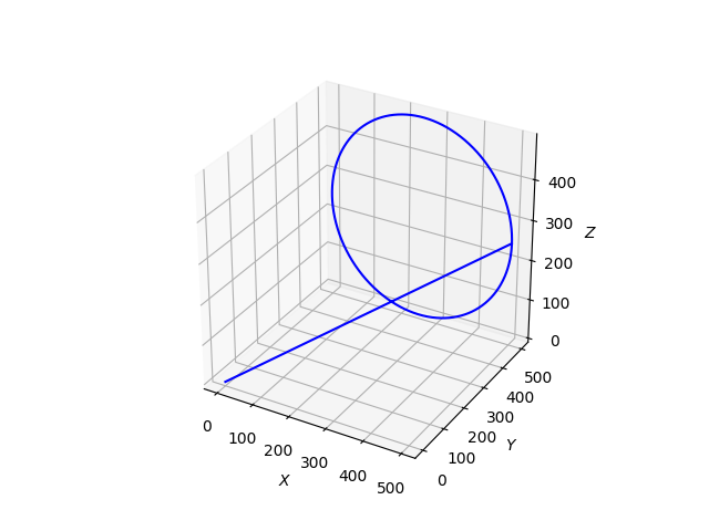
Incremental distance mode for I, J & K offsets. Is the default behaviour of the g-code parser. (See G2, G3, G17 and G18).
Example:
G90 G21 G61 G17 G91.1
G0 X500 Y250 Z500
G3 X0 Y250 I-250 J0
G3 X500 Y250 I250 J0
Format:
G17
Description:
Set the current plane to the XY plane. Affects G2 and G3 commands.
Example:
G90 G21 G61 G17 G90.1
G0 X500 Y250 Z500
G3 X0 Y250 I250 J250
G3 X500 Y250 I250 J250

Format:
G18
Description:
Set the current plane to the ZX plane. Affects G2 and G3 commands.
Example:
G90 G21 G61 G18 G90.1
G0 X500 Y500 Z250
G3 X0 Z250 I250 K250
G3 X500 Z250 I250 K250
Format:
G19
Description:
Set the current plane to the YZ plane. Affects G2 and G3 commands.
Example:
G90 G21 G61 G19 G90.1
G0 X250 Y500 Z500
G3 Y0 Z250 J250 K250
G3 Y500 Z250 J250 K250
Format:
T<x>
Description:
Prepares to change to tool x. The tool is not changed until an M6 is programmed (see M6). The T word may appear on the same line as the M6 or on a previous line. It is OK if T words appear on two or more lines with no tool change.
Arguments:
- x (integer): The tool number to be selected. Must be defined in the tool table (see: python example)
Example:
T1 M6 ; selects tool 1 and changes tool
M3 ; starts selected tool in the clockwise direction
Format:
M6
Description:
When called, M3, M4and M5 commands will be affected by the tool previously selected by the latest T command.
Example:
T1 M6 ; selects tool 1 and changes tool
M3 ; starts selected tool in the clockwise direction
Format:
G28.1
Description:
When called, the predefined position referred to in G28 is set to the current absolute position
Example:
G90 G21 G61
G0 X500
Y500
Z500
G28.1
G0 Y0
X0
G28
Format:
G92 <axis><offset> <axis><offset> ...
Description:
G92 makes the current point have the coordinates you want, where the axis words contain the axes you want. All axis words are optional, except that at least one must be used. If an axis word is not used for a given axis, the offset for that axis will be zero.
For example, consider the command G92 X7. If the current point is at X=4 and there is no G92 offset active, the current point will become X=7 and the origin will move -3 in X.
Arguments:
- axis (X|Y|Z): At least one axis must be specified
- offset (float): Current position of the axis to set.
Example:
G90 G21 G64 P10.0
G0 X500
Y500 Z500
G92 X0 Y0 Z0
G0 X-250 Y-250 Z-250
Format:
G94
Description:
Sets the feedrate mode to units per minute. Currently the only feedrate mode option
Example:
G91 G21 G61 G94
G0 X500 F1000 ; Feedrate of 1000 mm/minute
Movement and Tool Commands
Movement and tool commands are used to cause motion of axes and tools. Their behaviour is affected by preceding operational commands.
Format:
G0 <axis><position> <axis><position> ... F<feedrate>
Description:
Command linear motion of desired axes, where all the axis words are optional. The G0 is optional if the current motion mode is G0. This will produce coordinated motion to the destination point at the maximum rapid rate. G0 is typically used as a positioning move
Arguments:
- axis (X|Y|Z): Optional. Axis to move
- position (float): Optional. Incremental G91 or absolute G90 position of resulting move.
- feedrate (float): Optional. Desired linear speed of move in length units (see: G21, G20). Ensuing moves will move at this desired feedrate.
Example:
G90 G21 G64 P10.0
G0 X500 Y500 F1000
Z500
X0 Y0
Z0 F500
Format:
G1 <axis><position> <axis><position> ... F<feedrate>
Description:
Command linear motion of desired axes, where all the axis words are optional. The G1 is optional if the current motion mode is G1. This will produce coordinated motion to the destination point at the desired feed rate. G1 is typically used as a cutting move
Arguments:
- axis (X|Y|Z): Optional. Axis to move
- position (float): Optional. Incremental (G91 or absolute G90) position of resulting move.
- feedrate (float): Optional. Desired linear speed of move in length units (see: G21, G20). Ensuing moves will move at this desired feedrate.
Example:
G90 G21 G64 P10.0
G1 Y500 Z500 F1000
X500
Y0 Z0
X0 F500
Format:
G2 X<offset> Y<offset> Z<offset> i<center_x> j<center_y> k<center_z> F<feedrate>
Description:
Performs clockwise a 2D arc in the selected plane (see: G17, G18, G19). Arc starts at the current position and ends at the defined offsets (absolute if G90 is active, incremental if G91 is active). Size of the circular arc is defined by the arc center coordinates (absolute if G90.1 is active, incremental if G91.1 is active). Full circles must be defined by at least 2 G2 commands.
Arguments:
- offset (float): End position of arc in length units (see G21, G20). Only axes in selected plane are necessary (e.g. XY, YZ, ZX).
- center_<x|y|z> (float): Center point coordinates of the desired arc. Only axes in selected plane are necessary (e.g. XY, YZ, ZX).
- feedrate (float): Optional. Defines feedrate of ensuing moves in length units per second.
Example:
G61 G21 G17 ; select XY plane for arcs
G90 ; offsets are in absolute position mode
G90.1 ; center_<x|y|z> in absolute position mode
G0 X500
G0 Y250 Z500
G2 X0 Y250 I250 J250
Format:
G3 X<offset> Y<offset> Z<offset> i<center_x> j<center_y> k<center_z> F<feedrate>
Description:
Performs a counterclockwise 2D arc in the selected plane (see: G17, G18, G19). Arc starts at the current position and ends at the defined offsets (absolute if G90 is active, incremental if G91 is active). Size of the circular arc is defined by the arc center coordinates (absolute if G90.1 is active, incremental if G91.1 is active). Full circles must be defined by at least 2 G2 commands.
Arguments:
- offset (float): End position of arc in length units (see G21, G20). Only axes in selected plane are necessary (e.g. XY, YZ, ZX).
- center_<x|y|z> (float): Center point coordinates of the desired arc. Only axes in selected plane are necessary (e.g. XY, YZ, ZX).
- feedrate (float): Optional. Defines feedrate of ensuing moves in length units per second.
Example:
G61 G21 G17 ; select XY plane for arcs
G90 ; offsets are in absolute position mode
G90.1 ; center_<x|y|z> in absolute position mode
G0 X500
G0 Y250 Z500
G3 X0 Y250 I250 J250
Format:
G4 P<seconds>
Description:
Causes the machine to stay in place for a period of time.
Arguments:
- seconds (float): Time in seconds the machine will stay stationary
{:/accordion}
{::accordion title=’G28: Move To Predefined Position’ code=’’}
Format:
G28
Description:
Causes the machine to return to its predefined position, as set in G28.1. If no position is previously set, machine will return to the origin.
Example:
G90 G21 G61
G0 X500
Y500
Z500
G28.1
G0 Y0
X0
G28
Format:
Implicit method:
M3 $<tool number>
Explicit method:
M3 A<device ID> P<port>
Description:
Used for interfacing with end of arm tools that are linked to digital outputs. When called, the selected tool (and as a result, the associated digital output) will be activated to cause a clockwise rotation of the tool. Tools can be controlled implicitly or explicitly. The implicit method of tool control relies on external definition of the tool via python API.
Arguments:
Implicit Method:
- tool number (int): Optional. If used, controls the given tool number. The associated clockwise output will be pulled active, while the counterclockwise output will be pulled inactive. If not used, M3 will control the last activated tool (see: T, M6).
Explicit Method:
- device ID (int): Directly selects the desired digital output’s device ID.
- port (int): Directly sets the desired port value to HIGH (24V).
Example:
Implicit Method:
Python Snippet:
from MachineMotion import *
clockwise = DIGITAL_OUTPUT_STATE(deviceId=1,port=0,value=1)
counterclockwise = DIGITAL_OUTPUT_STATE(deviceId=1,port=1,value=1)
tool1 = TOOL(1,clockwise,counterclockwise)

m = MachineMotionV2()
m.configPathMode({"X": 1, "Y": 2},tool1)
G-Code Snippet:
G90 G21
T1 M6 ; selects tool one and activates it
G0 X100 Y100
M3 ; starts activated tool clockwise
G1 X200 Y200
M5 ; stops activated tool
Explicit Method:
G90 G21
G0 X100 Y100
M3 A1 P0 ; Pulls device ID 1 port 0 HIGH
G1 X200 Y200
M5 A1 P0 ; Pulls device ID 1 port 0 LOW
Format:
Implicit method:
M3 $<tool number>
Explicit method:
M3 A<device ID> P<port>
Description:
Used for interfacing with end of arm tools that are linked to digital outputs. When called, the selected tool (and as a result, the associated digital output) will be activated to cause a counterclockwise rotation of the tool. Tools can be controlled in two ways: implicitly with the “$” operator method and directly with the “A”,”P” method. The implicit method relies on external definition of the tool via python API.
Arguments:
Implicit Method:
- tool number (int): Optional. If used, controls the given tool number. The associated counterclockwise output will be pulled active, while the counterclockwise output will be pulled inactive. If not used, M4 will control the last activated tool (see: T, M6).
Explicit Method: - device ID (int): Directly selects the desired digital output’s device ID.
- port (int): Directly sets the desired port value to HIGH (24V).
Example:
Implicit Method:
Python Snippet:
from MachineMotion import *
clockwise = DIGITAL_OUTPUT_STATE(deviceId=1,port=0,value=1)
counterclockwise = DIGITAL_OUTPUT_STATE(deviceId=1,port=1,value=1)
tool1 = TOOL(1,clockwise,counterclockwise)

m = MachineMotionV2()
m.configPathMode({"X": 1, "Y": 2},tool1)
G-Code Snippet:
G90 G21
T1 M6 ; selects tool one and activates it
G0 X100 Y100
M4 ; starts activated tool counterclockwise
G1 X200 Y200
M5 ; stops activated tool
Explicit Method:
G90 G21
G0 X100 Y100
M4 A1 P1 ; Pulls device ID 1 port 1 HIGH
G1 X200 Y200
M5 A1 P1 ; Pulls device ID 1 port 1 LOW
Format:
Implicit method:
M3 $<tool number>
Explicit method:
M3 A<device ID> P<port>
Description:
Used for interfacing with end of arm tools that are linked to digital outputs. When called, the selected tool (and as a result, the associated digital output) will be activated to cause a clockwise rotation of the tool. Tools can be controlled in two ways: implicitly with the “$” operator method and directly with the “A”,”P” method. The implicit method relies on external definition of the tool via python API.
Arguments:
Implicit Method:
- tool number (int): Optional. If used, controls the given tool number. The associated clockwise and counterclockwise outputs will be pulled inactive. If not used, M5 will control the last activated tool (see: T, M6).
Explicit Method: - device ID (int): Directly selects the desired digital output’s device ID.
- port (int): Directly sets the desired port value to LOW (0V).
Example:
Implicit Method:
Python Snippet:
from MachineMotion import *
clockwise = DIGITAL_OUTPUT_STATE(deviceId=1,port=0,value=1)
counterclockwise = DIGITAL_OUTPUT_STATE(deviceId=1,port=1,value=1)
tool1 = TOOL(1,clockwise,counterclockwise)

m = MachineMotionV2()
m.configPathMode({"X": 1, "Y": 2},tool1)
G-Code Snippet:
G90 G21
T1 M6 ; selects tool one and activates it
G0 X100 Y100
M3 ; starts activated tool clockwise
G1 X200 Y200
M5 ; stops activated tool
Explicit Method:
G90 G21
G0 X100 Y100
M3 A1 P0 ; Pulls device ID 1 port 0 HIGH
G1 X200 Y200
M5 A1 P0 ; Pulls device ID 1 port 0 LOW
Python Example
import sys
sys.path.append("../..")
from MachineMotion import *

mm = MachineMotionV2()

### This example demonstrates the creation and execution of a simple 2D path ###
# Expected configuration for this example (via Control Center)
# Axis 1
#   Drive Number(s): 1, 2
#   Axis Type: Enclosed Timing Belt with 5:1 gearbox
#   Motor Size: Large
# Axis 2
#   Drive Number(s): 3
#   Axis Type: Enclosed Ballscrew
#   Motor Size: Large

GCODE_STRING = """
(Operational mode commands)
G90   ; Absolute position mode
G90.1 ; Absolute arc centre
G21   ; Use millimeter units
G17   ; XY plane arcs
G64 P0.5 ; Blend move mode, 0.5 mm tolerance

(Movement and output commands)
G0 X60 Y110 F1000 ; Travel move at 1000 mm/minute
M3 $1 ; Start tool 1 in clockwise direction
G1 X110 Y110
G2 X110 Y10 I100 J60 ; Clockwise arc
G1 X60 Y10
G2 X60 Y110 I60 J60
G4 P1.0 ; Dwell for 1 second
M5 $1 ; Stop tool 1
G0 X1 Y1
"""

# Optional: If your path contains M3-4-5 commands,
# define device,port and on value of both tool directions.
# clockwise must be defined for M3 commands
clockwise = DIGITAL_OUTPUT_STATE(deviceId=1, port=0, value=1)
counterClockwise = DIGITAL_OUTPUT_STATE(1, 1, 1)
tool1 = TOOL(1, clockwise, counterClockwise)
# associate with the parent drive
driveAssociation = {"X": 1, "Y": 3}
# Configure the path following mode
mm.configPathMode(driveAssociation, tool1)
maxPathAcceleration = 1000  # mm/s^2

mm.setAxisMaxAcceleration(1,1000)
mm.setAxisMaxAcceleration(3,1000)
mm.setAxisMaxSpeed(1,500)
mm.setAxisMaxSpeed(3,500)

mm.moveToHome(1)
mm.moveToHome(3)
mm.waitForMotionCompletion()

# Start Path Following.
mm.startPath(GCODE_STRING, maxPathAcceleration)
running = True
while running:
    pathStatus = mm.getPathStatus()
    running = pathStatus['running']
    print('--> Got Path Status: ', pathStatus)
    time.sleep(0.5)

mm.stopPath()
print("--> Done!")