Muting Safety Module Datasheet
Contents
- Overview
- Features
- Included cables
- Important Notes
- Safety
- Technical specs
- General Specifications
- Electrical Specifications
- Physical Interface
- LED Indicators
- Functionality
- Port definitions
- Device 1 & 2 - Pin-out - M12, female, 12-pin, A-Keyed
- Device 3 & 4 - Pin-out - M12, female, 12-pin, A-Keyed
- Muting ports 3/4A & 3/4B - Pin-out - M12, female, 4-pin, A-Keyed
- Safety OUT - Pin-out - M12, male, 12-pin, A-Keyed
- Safety IN - Pin-out - M12, female, 12-pin, A-Keyed
- Mounting
- Wiring Diagram
- PNP Sensor Muting Configuration
- Safety Data
- Documentation for Previous Product Versions
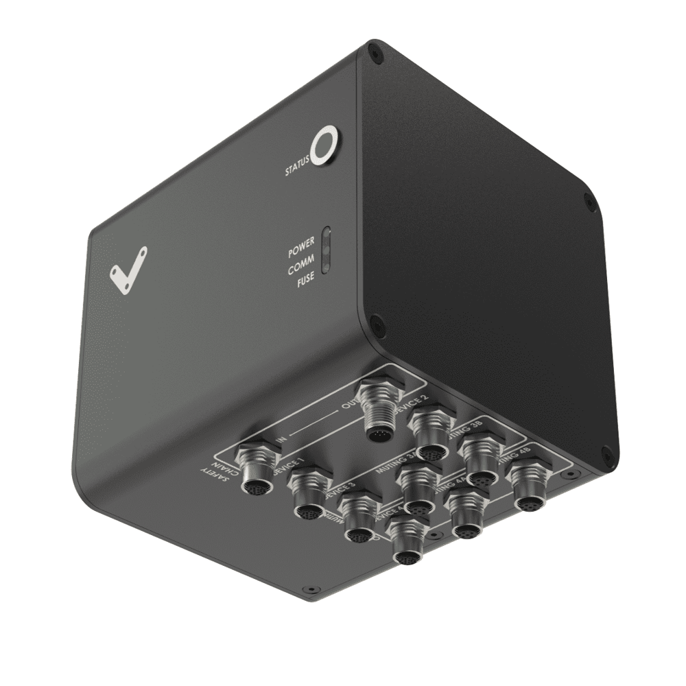
Overview
The Muting Safety Module (CE-SA-015-0001) is essential when an emergency stop (e-stop) function is required in the machine, ensuring a critical layer of safety. Additionally, it can be used to mute light curtains or light scanners, allowing the passage of objects like boxes on a conveyor without triggering an e-stop. This module interfaces with up to four safety devices on MachineMotion V2 and is the default safety module for safety systems. It can connect to area scanners, light curtains, and other safety devices to perform safety functions, which are essential for reducing risk. Every safety equipment deployment should be paired with a safety assessment.
This datasheet provides technical specifications for Vention’s latest Muting Safety Module. For details on Vention’s Safety Modules V2.0 and V3.0, refer to the ‘Documentation for Previous Product Versions’ section at the bottom of this page.
Features
- Configuration-free, plug-and-play
- Compatible with MachineMotion V2
- Daisy-chainable
- Compatible with Datalogic SG4 & Keyence GL-R light curtains
- Compatible with Datalogic & Keyence laser scanners
- Inputs for 2 pairs of muting sensors (CE-AP-002-0000 compatible)
- On-board LED to indicate power, fuse and communication
- RGB LED for any other status (software programmable)
- Reports safety states to the MachineMotion controller
- Safety OUT latching
Included cables
- 1x Safety Extension cable (5m) - CE-CA-102-5001__2
- 3x Safety Device Jumper - CE-SA-125-0001
- 1x Safety Jumper - CE-SA-102-0001
Important Notes
Safety

Vention’s safety modules perform safety functions as a part of a whole installation or machine. A complete safety system normally includes sensors or input units, logic units and contactors or output units. The manufacturer of the installation or machine is responsible for ensuring proper functioning of the whole system. The total concept of the control system into which the safety module is integrated must be validated by the user. Vention cannot guarantee all specifications of an installation or a machine without being responsible for the risk assessment and the design of the safety system. Vention takes over no liability for recommendations which are given or implied in the following description.
The following items must be taken into consideration during the design, risk assessment & installation of the safety system :
- The Safety Modules shall be put into operation only after the safety functions have been tested during the commissioning.
- According to EN IEC 60204-1:2018 and EN ISO 10218-1:2011 it is not allowed to restart automatically after emergency stop. Therefore the control systems of the connected devices have to disable the automatic start after emergency stop.
- Opening the Safety Module or implementing unauthorized changes voids any warranty.

Functional error! Danger to life, risk of serious injuries or property damage
- The Muting Safety Module may only be connected to the equipment listed in this manual.
- The Muting Safety Module does not monitor the input redundant signals at the safety device ports. If the connected devices do not have monitoring of its output signals, the performance level of the safety function can be reduced.
- The Muting function is not considered to be a safety function.
- Muting must only be performed on Material. A risk assessment shall be performed to verify that the use of the muting function does not create new hazards. Refer to IEC/TS 62046 for additional considerations when applying muting.
- The risk assessment shall demonstrate that when triggering the safety devices connected to the Device ports, the state of the machine and the safety distance are acceptable;
- The Muting Safety Module is designed to operate in indoor environments without dust or high humidity. Dust and dampness may lead to malfunction. Do not install or operate the Muting Safety Module outdoors.
- The machine shall be designed in such a way that it is not possible to press the reset button from inside a safeguarded area without triggering one of the devices connected to the Device ports.
Technical specs
General Specifications
| Item | Specification |
|---|---|
| Part Number | CE-SA-015-0001 |
| Weight | 0.8kg |
| Dimensions | 19.0 x 15.0 x 9.0mm |
| Material |
|
| Operating Temp | 0 to 40°C |
Electrical Specifications
| Item | Specification |
|---|---|
| Nominal input voltage | 24 VDC (Class 2 or SELV power supply** |
| Input voltage range | 19.2 ~ 26.4 VDC |
| Operating power consumption |
|
| Peak power consumption |
|
| Compatible muting sensor output type | NO, PNP |
| Short circuit protection | Internal E-FUSE IC* |
| Max current allowed | 2 A |
| Post-short current | 250 mA |
| Release delay at 24 V | < 40 ms |
*Note: Due to the inrush of safety devices, the E-FUSE might trip if you power the unit while 4 or more Safety devices are plugged into it. To fix this issue, you can remove power from the MachineMotion and start it again.
** Note: In North America the Safety Module shall be supplied by a certified class 2 power supply. In Europe, the Safety Module must be supplied by an SELV circuit. When powered by the MachineMotion those requirements are met.
Physical Interface
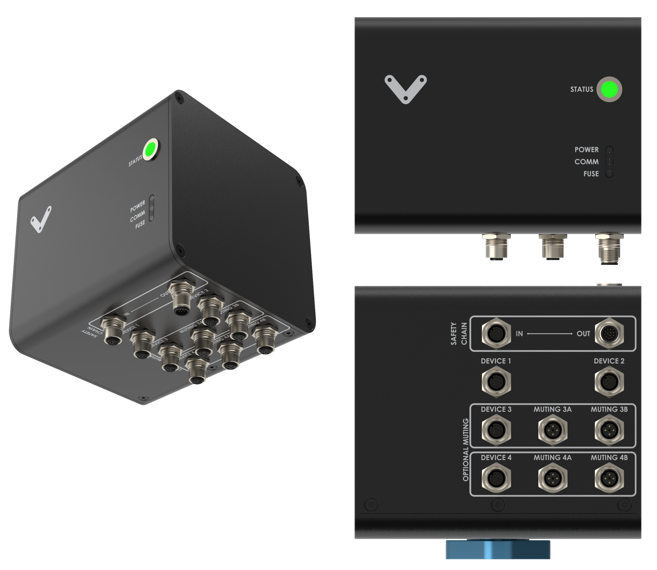
LED Indicators
| Name | LED Color | Indicated (when ON) |
|---|---|---|
| POWER | White | 24 VDC supplied to module |
| COMM | White | EtherNet communication functional |
| FUSE | Red | Module internal fuse tripped |
| STATUS | Off | Disconnected |
| STATUS | Green | Connected |
| STATUS | White | Communication issue |
| STATUS | Orange | Error |
| STATUS | Red | E-Stop |
| STATUS | Blinking Red | User triggered E-Stop |
| STATUS | Blinking Blue | Muting active |
Functionality
Device 1 and device 2 will trigger the safety out immediately. Device 3 and device 4 will trigger safety out immediately except if in the muting state.
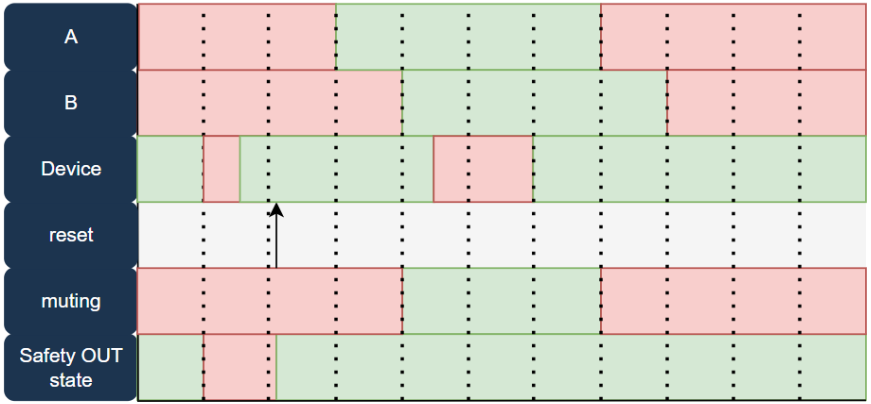
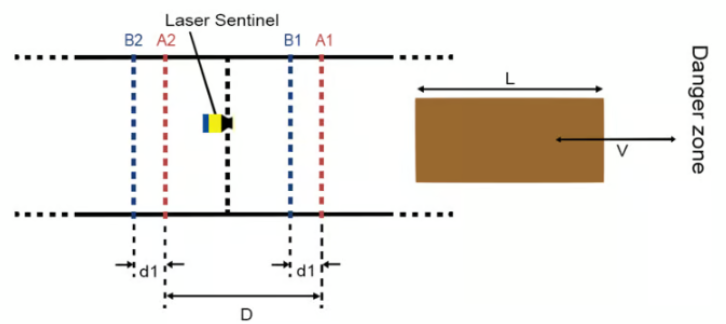
The Muting State is triggered when the corresponding A channel becomes triggered followed by the B channel. The sensors come from the muting kit (CE-AP-002-0000) and placed in a specific order to activate the Muting for Material.
The muting sensors A and B must be triggered within 2 seconds for the muting to occur. The order does not matter. Activating the muting sensors for more than 10 consecutive seconds will disable muting. The physical positioning of the sensors is critical for proper function and safety.
Port definitions
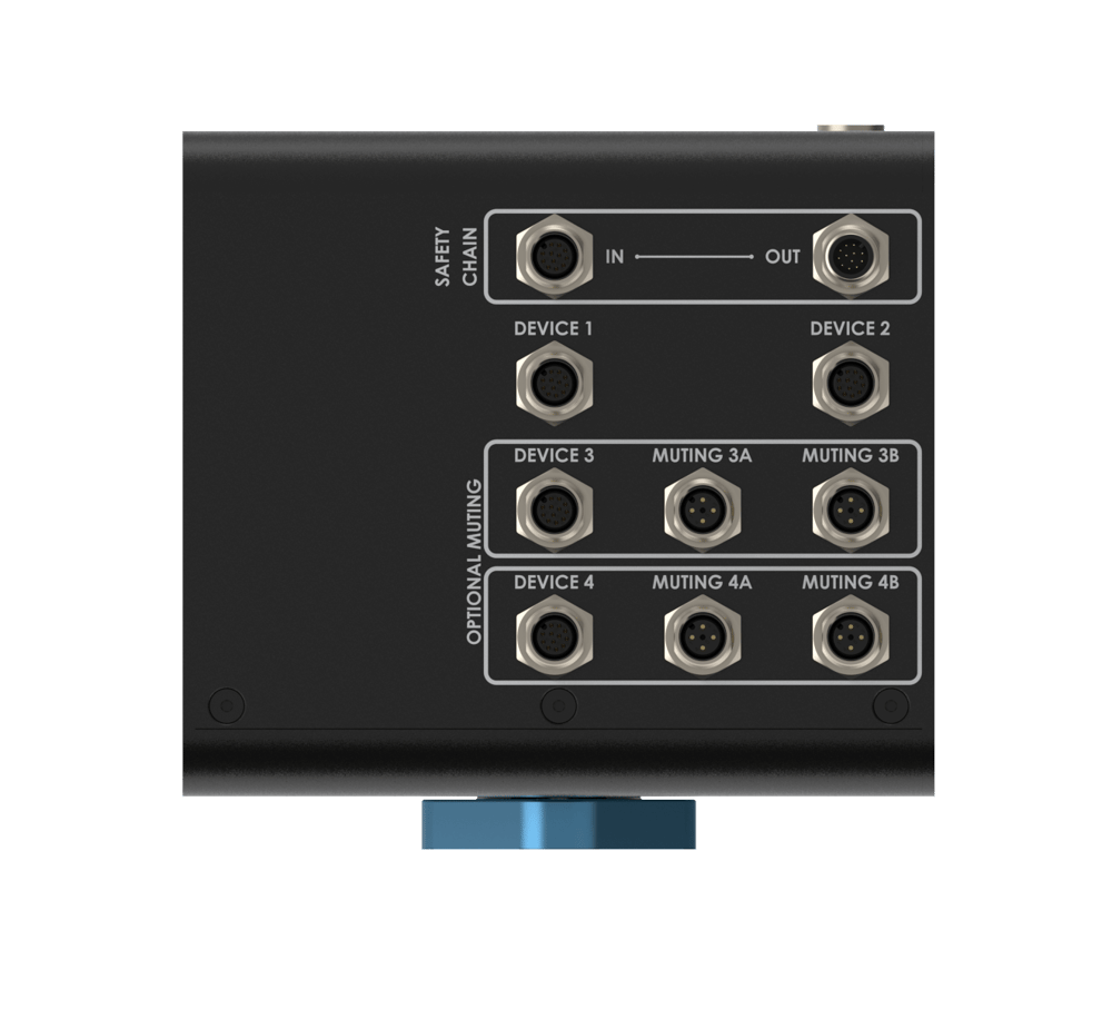
Device 1 & 2 - Pin-out - M12, female, 12-pin, A-Keyed
Device 1 & Device 2 ports connect to safety devices and will always trigger the safety out port.
| Pin | Function |
|---|---|
| Pin 1 | 24V fused |
| Pin 2 | 0V |
| Pin 3 | NC |
| Pin 4 | NC |
| Pin 5 | OSSD input 1 |
| Pin 6 | NC |
| Pin 7 | NC |
| Pin 8 | OSSD input 2 |
| Pin 9 | NC |
| Pin 10 | NC |
| Pin 11 | NC |
| Pin 12 | NC |
Device 3 & 4 - Pin-out - M12, female, 12-pin, A-Keyed
Device 3 and device 4 ports connect to safety devices and can be muted.
| Pin | Function |
|---|---|
| Pin 1 | 24V fused |
| Pin 2 | 0V |
| Pin 3 | NC |
| Pin 4 | NC |
| Pin 5 | OSSD input 1 |
| Pin 6 | NC |
| Pin 7 | NC |
| Pin 8 | OSSD input 2 |
| Pin 9 | NC |
| Pin 10 | NC |
| Pin 11 | NC |
| Pin 12 | NC |
Muting ports 3/4A & 3/4B - Pin-out - M12, female, 4-pin, A-Keyed
Muting 3/4A and Muting 3/4B ports connect to a muting kit (CE-AP-002-0000). A correct sequence will mute the associated port.
| Pin | Function |
|---|---|
| Pin 1 | 24V fused |
| Pin 2 | Input (PNP) |
| Pin 3 | 0V |
| Pin 4 | NC |
Safety OUT - Pin-out - M12, male, 12-pin, A-Keyed
The Safety OUT port connects to the SAFETY IN port of another Safety Module (if daisy-chaining multiple safety modules) or to a MachineMotionV2.
| Pin | Function |
|---|---|
| Pin 1 | 24 VDC |
| Pin 2 | 0V |
| Pin 3 | SAFETY OUT 11 |
| Pin 4 | SAFETY OUT 12 |
| Pin 5 | SAFETY OUT 21 |
| Pin 6 | SAFETY OUT 22 |
| Pin 7 | RESET +(24V) |
| Pin 8 | RESET - (OUTPUT) |
| Pin 9 | ETHERNET TX+ (auto-MDIX) |
| Pin 10 | ETHERNET TX- (auto-MDIX) |
| Pin 11 | ETHERNET RX+ (auto-MDIX) |
| Pin 12 | ETHERNET RX- (auto-MDIX) |
Safety IN - Pin-out - M12, female, 12-pin, A-Keyed
The Safety IN port connects to the SAFETY OUT port of another Safety Module (if daisy-chaining multiple safety modules) or to an E-Stop and Reset Module (CE-SA-007-0000). IMPORTANT: If the SAFETY IN port is not used, insert the included yellow jumper.
| Pin | Function |
|---|---|
| Pin 1 | 24 VDC |
| Pin 2 | 0V |
| Pin 3 | SAFETY IN11 |
| Pin 4 | SAFETY IN 12 |
| Pin 5 | SAFETY IN 21 |
| Pin 6 | SAFETY IN 22 |
| Pin 7 | RESET +(24V) |
| Pin 8 | RESET - (INPUT) |
| Pin 9 | ETHERNET TX+ (auto-MDIX) |
| Pin 10 | ETHERNET TX- (auto-MDIX) |
| Pin 11 | ETHERNET RX+ (auto-MDIX) |
| Pin 12 | ETHERNET RX- (auto-MDIX) |
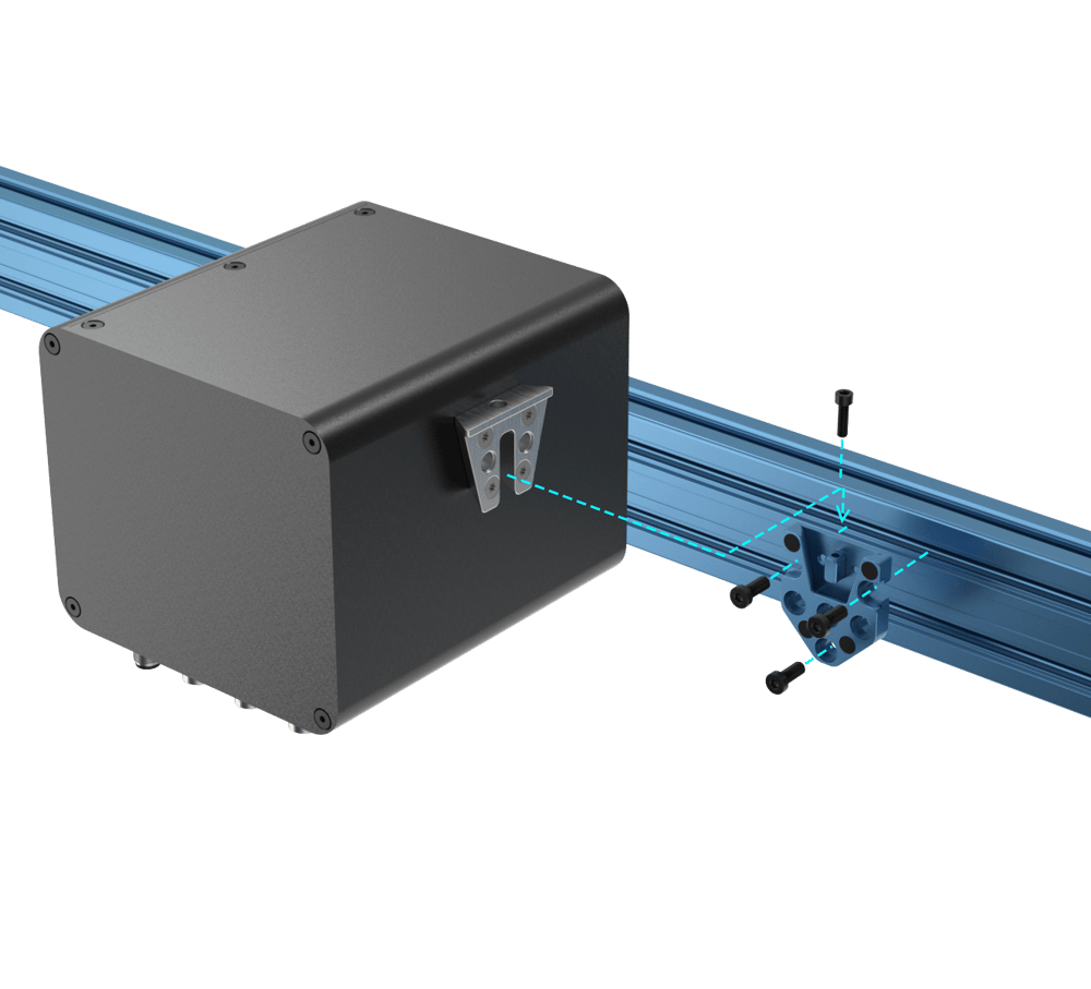
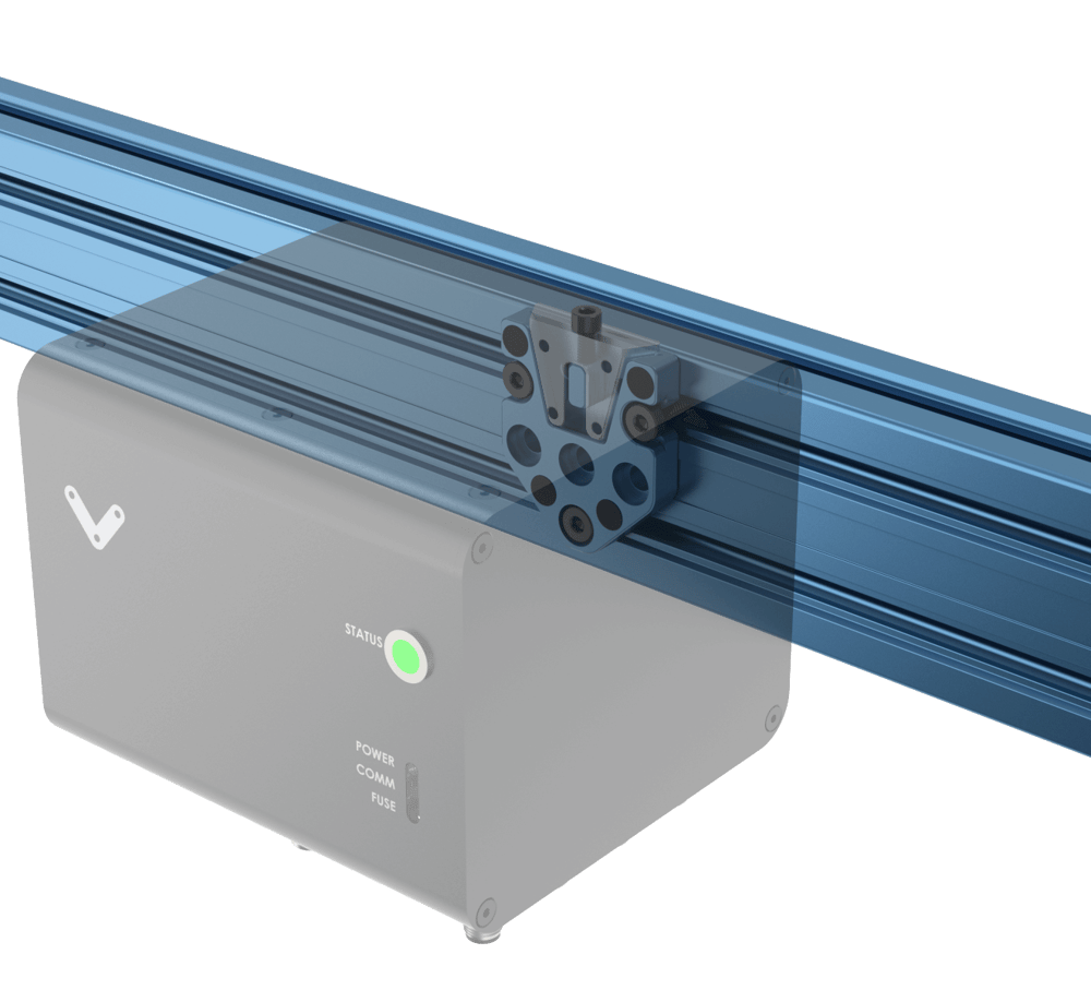
Mounting
Install the module mounting bracket (CE-HW-005-1002) to the extrusion with the screws provided (HW-FN-003-0018). Install the module onto the mounting bracket as illustrated below.
Wiring Diagram

*Note: Insert a black jumper into any unused input on this safety module for proper functionality. Yellow jumpers are reserved for unused safety ports on MachineMotion.
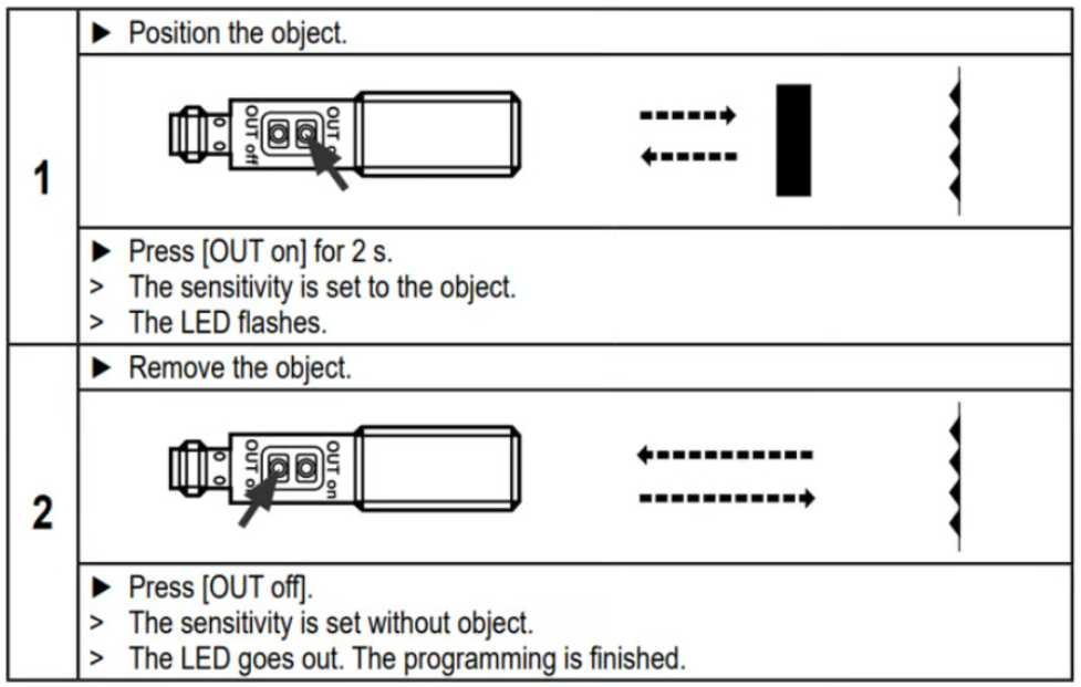
PNP Sensor Muting Configuration
When muting with Vention Muting kit (CE-AP-002-0000), please use the procedure below to configure the PNP sensors.
Safety Data
The Vention’s Safety Modules realize the following safety functions :
- System emergency stop output at the Safety OUT connector from the Safety IN port (E-stop_SafetyIN-to-SafetyOUT);
- The Device port (light-curtain or area scanner) to the Safety OUT port System emergency stop output at the Safety OUT connector from a Safety Device port (E-stop_Device-to-SafetyOUT); and
- System reset propagation from the Safety IN port to the Safety OUT port (Reset_SafetyOUT).
For each of these functions, safety data can be found in the following table.
For each of these functions performed by the Robot Safety Module, safety data can be found in the following table:
| Safety Function | PL | Cat. | MTTFd | DCavg | PFHd |
|---|---|---|---|---|---|
| E-stop_SafetyIN-to-SafetyOUT | e | 3 | 186 | 99% | 4.29E-08 |
| E-stop_Device-to-SafetyOUT | e | 3 | 186 | 99% | 4.29E-08 |
| Reset_SafetyOUT | c | 1 | >100 | N/A | 1.14E-06 |
The above information have been calculated based on the following operation conditions:
| Data | Value | Unit |
|---|---|---|
| dop | 365 | days/years |
| hop | 24 | hours/days |
| tcycle | 8640 | s/cycle |