Dorner 2200 Belt Conveyor
Overview
Use this technical document to guide your selection of belt conveyor size, power transmission options, to ensure that you buy the correct combination of components for your application. This document will outline how to calculate the required forces to transfer your goods as well as the corresponding powertrain combinations to meet those requirements.
Applications
Applications for belt conveyors are diverse, but at their core, a belt conveyor is always used to move an object from position A to position B. Applications vary from simple conveying systems to complex pick and place systems with indexing and part accumulation. Check out our design library for inspiration.
Technical Specifications
| 152mm Wide | 305 to 610 mm Wide | |
|---|---|---|
| Rated Payload Pulling (kg)* | 27.2 | 36.3 |
| Rated Payload Pushing (kg)* | 13.6 | 18.2 |
| Displacement Ratio (mm/turn) | 73.563 | 73.563 |
| Max Speed (mm/s) | 2000 | 2000 |
| Belt Material | Very Low Friction Urethane | Very Low Friction Urethane |
| Coefficient of friction between the conveyor belt and its bed surface | 0.33 | 0.33 |
* Note: the rated load of the conveyor is not the same in both directions because of the end drive configuration. The belt can move a larger payload when it is moving the payload towards the motor (pulling) compared to when the payload is moving away from the motor (pushing).
Above ratings for maximum payload are calculated at equilibrium and assume a horizontal conveyor. The limiting factor is slip between the belt and conveyor pulley. To determine the correct powertrain for more complex applications that include accelerations and inclines see the Calculating Required Driving Force section on this page.
Ambient temperature and number of starts and stops of your conveyor can affect the payload capacity of your conveyor based on the following formula:
Payload = (Rated Payload from the above table)x(Temperature Factor)x(Start/Stop Factor)
Ambient temperature can have a negative effect on the payload of the conveyor. You can find the temperature factor in the following table.
| Temperature (C) | Temperature Factor |
|---|---|
| -20 | 1.0 |
| 0 | 1.0 |
| 20 | 1.0 |
| 40 | 0.9 |
| 60 | 0.8 |
Also, frequent starts/stops of the conveyor can have a negative effect on the payload of the conveyor. You can find the start/stop factor in the following table.
| Application Condition | Start/Stop Factor |
|---|---|
| Continuous Run or 1 start/stop per hour | 1.0 |
| Maximum 10 starts/stop per hour | 0.83 |
| Maximum 30 starts/stop per hour | 0.70 |
| Greater than 30 starts/stop per hour | 0.62 |
Available Sizes
| Conveyor Length | 152 mm Width | 305 mm Width | 457 mm Width | 610 mm Width |
|---|---|---|---|---|
| 585 | MO-CV-004-0585 | MO-CV-005-0585 | MO-CV-006-0585 | MO-CV-007-0585 |
| 765 | MO-CV-004-0765 | MO-CV-005-0765 | MO-CV-006-0765 | MO-CV-007-0765 |
| 945 | MO-CV-004-0945 | MO-CV-005-0945 | MO-CV-006-0945 | MO-CV-007-0945 |
| 1125 | MO-CV-004-1125 | MO-CV-005-1125 | MO-CV-006-1125 | MO-CV-007-1125 |
| 1305 | MO-CV-004-1305 | MO-CV-005-1305 | MO-CV-006-1305 | MO-CV-007-1305 |
| 1530 | MO-CV-004-1530 | MO-CV-005-1530 | MO-CV-006-1530 | MO-CV-007-1530 |
| 1710 | MO-CV-004-1710 | MO-CV-005-1710 | MO-CV-006-1710 | MO-CV-007-1710 |
| 1890 | MO-CV-004-1890 | MO-CV-005-1890 | MO-CV-006-1890 | MO-CV-007-1890 |
| 2070 | MO-CV-004-2070 | MO-CV-005-2070 | MO-CV-006-2070 | MO-CV-007-2070 |
| 2295 | MO-CV-004-2295 | MO-CV-005-2295 | MO-CV-006-2295 | MO-CV-007-2295 |
| 2475 | MO-CV-004-2475 | MO-CV-005-2475 | MO-CV-006-2475 | MO-CV-007-2475 |
| 2655 | MO-CV-004-2655 | MO-CV-005-2655 | MO-CV-006-2655 | MO-CV-007-2655 |
| 2835 | MO-CV-004-2835 | MO-CV-005-2835 | MO-CV-006-2835 | MO-CV-007-2835 |
| 3060 | MO-CV-004-3060 | MO-CV-005-3060 | MO-CV-006-3060 | MO-CV-007-3060 |
| 3240 | MO-CV-004-3240 | MO-CV-005-3240 | MO-CV-006-3240 | MO-CV-007-3240 |
Suggested Mounting
Optimal conveyor mounting depends on the payload as well as the width and length of the conveyor. The following table can be used as a conservative guide. The mounting points should be spaced as evenly as possible. The number in the light blue section corresponding to the length and width of your conveyor indicates the suggested number of brackets to be used.
| Length (mm) | Width (mm) | Number of brackets |
|---|---|---|
| 585 - 1305 | 152 | 4 |
| 585 - 1305 | 305 | 4 |
| 585 - 1305 | 457 | 4 |
| 585 - 1305 | 610 | 4 |
| 1530 - 2070 | 152 | 4 |
| 1530 - 2070 | 305 | 4 |
| 1530 - 2070 | 457 | 4 |
| 1530 - 2070 | 610 | 6 |
| 2295 - 2655 | 152 | 6 |
| 2295 - 2655 | 305 | 6 |
| 2295 - 2655 | 457 | 6 |
| 2295 - 2655 | 610 | 8 |
| 2835 - 3240 | 152 | 6 |
| 2835 - 3240 | 305 | 6 |
| 2835 - 3240 | 457 | 8 |
| 2835 - 3240 | 610 | 8 |
Calculation Required Driving Force
To calculate the required linear force to drive your payload a few things must be considered. Main considerations are the desired acceleration of the belt when starting, the force required to deform the belt over the rollers, if the belt is on an incline or not, and what the friction generated by the payload is. The sum of these four forces will give the required linear force of the belt conveyor.
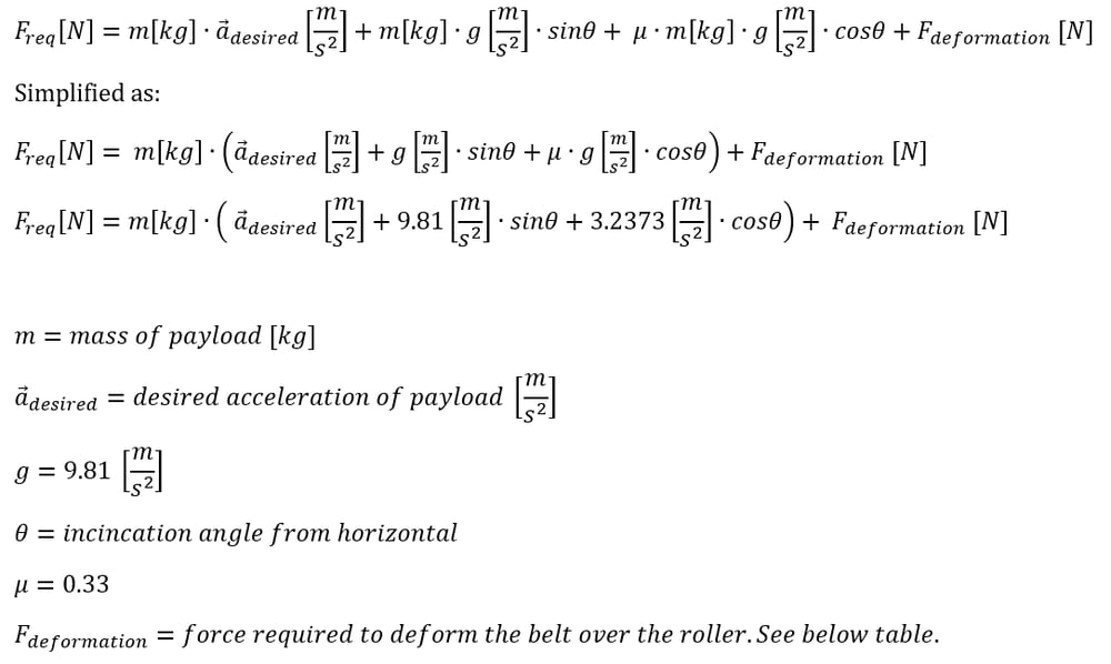
The deformation force for each conveyor width is provided in the table below. This value represents the torque and equivalent force required to deform the belt over the conveyor rollers. The value also includes other small parasitic losses in the system.
| Belt Width (mm) | Deformation Force (N) |
|---|---|
| 152 | 56.5 |
| 305 | 98.9 |
| 457 | 120 |
| 610 | 141 |
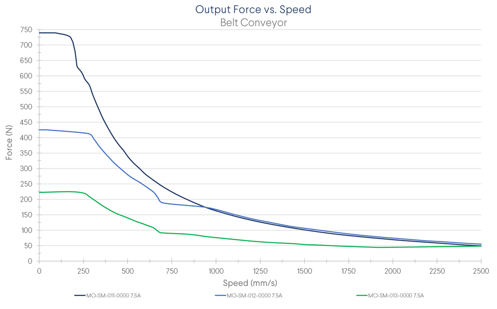
After the required driving force has been calculated, compare it to the force vs speed graph below.
As an example, a conveyor needs to move a load of 20 kg at 500mm/s up a 10 degree incline. The conveyor must occasionally be able to accelerate the mass at 0.5m/s^2. The width of the belt conveyor is 457mm.
In this case our variables are 20kg for mass, 0.5m/s^2 for acceleration, 10 degrees for angle theta, and 120N for deformation force. These variables lead to a required driving force of 227.8N and 500mm/s. Looking at the Force vs speed graph below it can be seen that the MO-SM-011-0000 or MO-SM-012-0000 motors will be required to meet these requirements.
Force vs. Speed
Once the motor type has been selected based on required force and speed you can add the appropriate part to your design.
Assembly Instructions
- Assemble the Vention extrusion frame
- If a 457mm or 610mm wide conveyor was ordered, follow the assembly instructions included in the package from Dorner.
- Install the Vention Belt Conveyor Mounting Brackets to the T-slot on the Dorner Conveyor using the included T-bar and M6 fasteners. Tighten finger tight only.
- Mount the conveyor onto the extrusion frame and connect the brackets to the extrusions using the included M8 fasteners. Once the conveyor is mounted in place, tighten the brackets which connect to the conveyor.
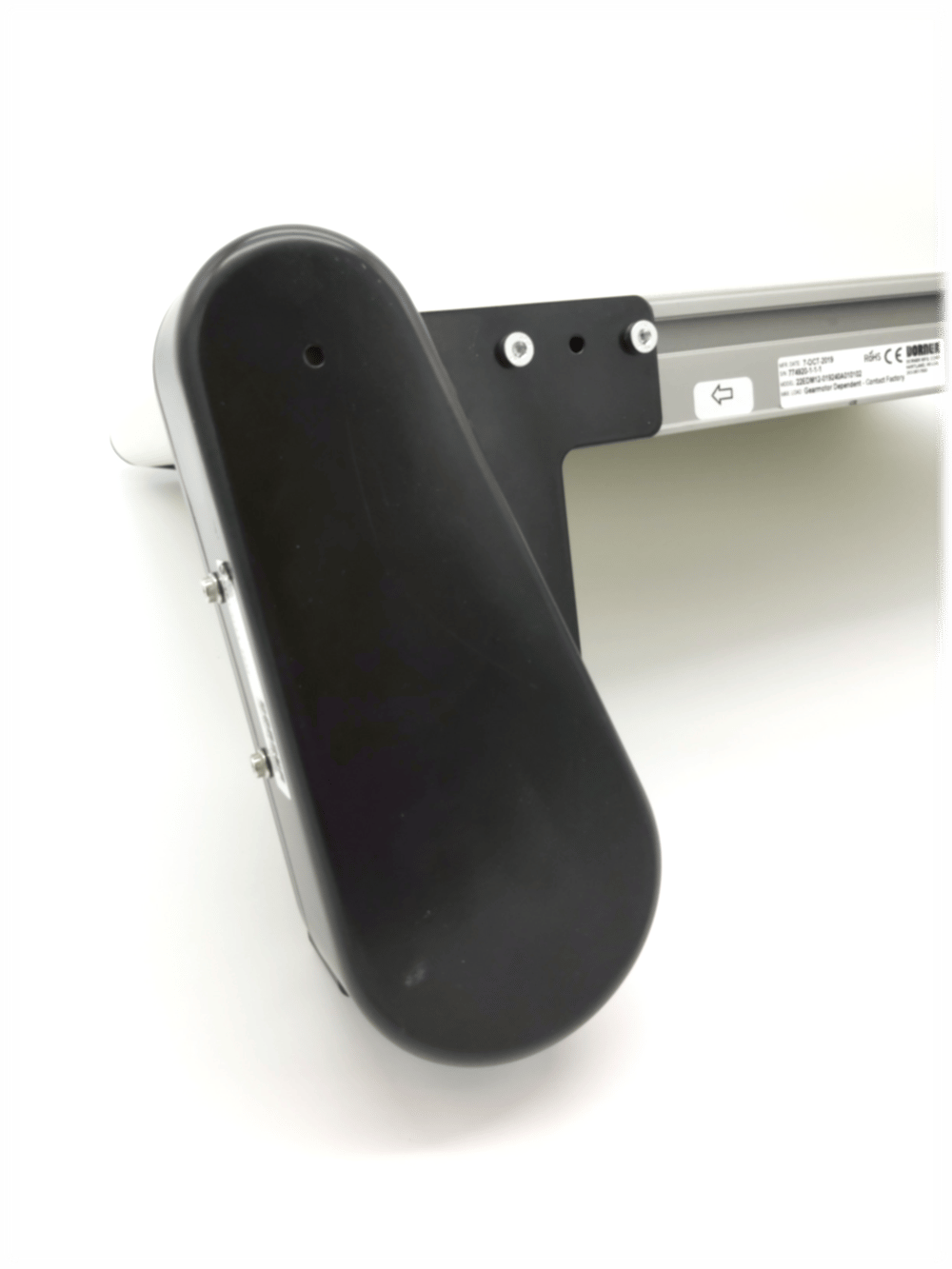
- Install your Vention NEMA 34 motor to the input shaft of the belt conveyor motor mount.
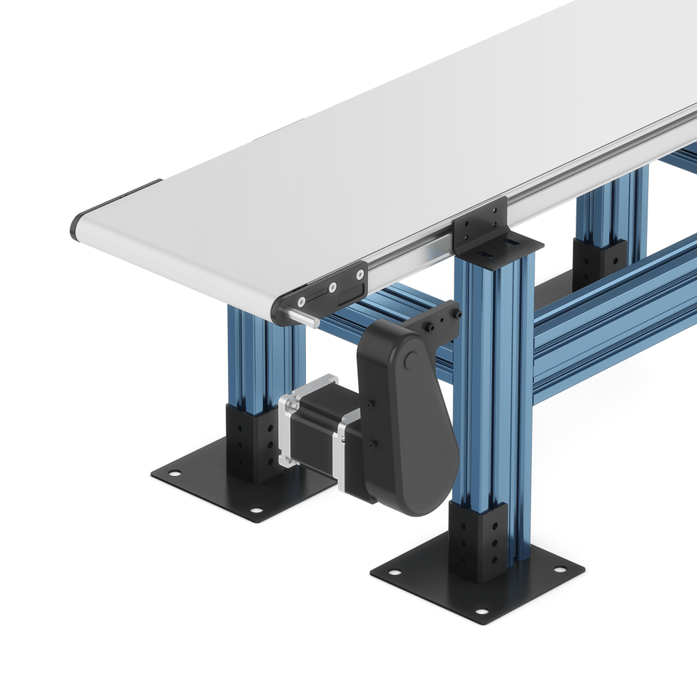
- Install the Vention compatible motor mount to the Dorner conveyor input shaft. The below images show the installation process provided by Dorner. Motor and mounting features will vary from the images below as the motor mount provided by Vention is a specialized model.
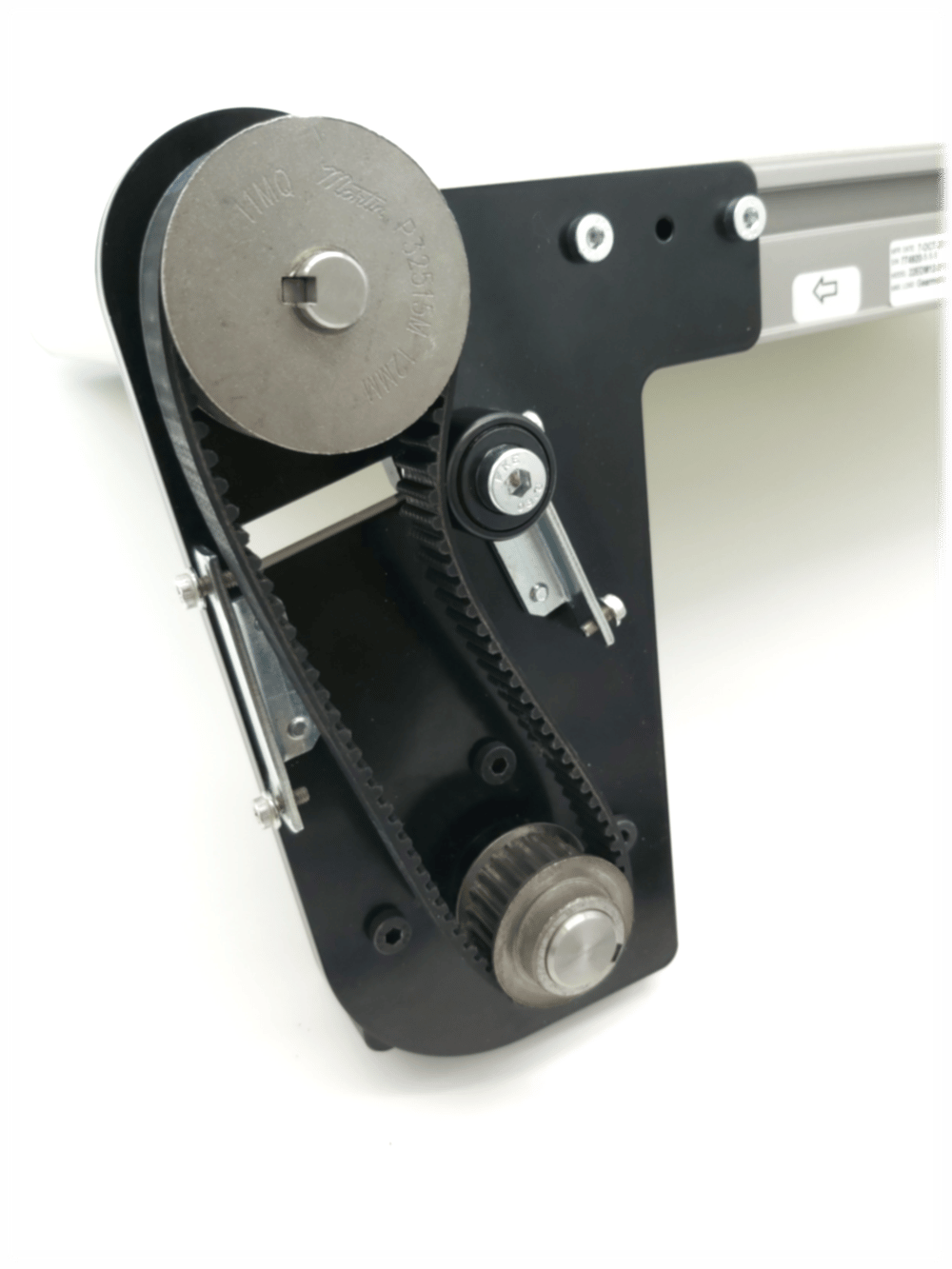
- The following image shows the contents of the motor mount kit.
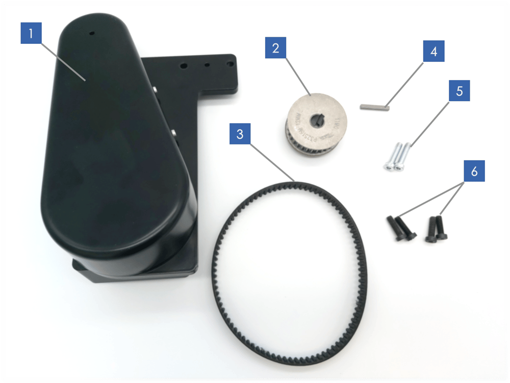
- Vention X Dorner Motor Mount
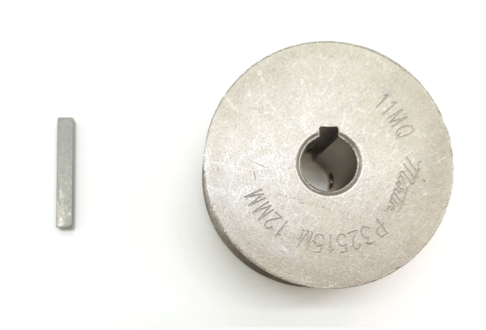
- Driven pulley with 12mm bore
- Timing Belt
- Key for the driven pulley
- M6 fasteners used for mounting the motor mount
- M6 fasteners used to install a Vention motor to the motor mount
- Attach the motor mount (1) to the conveyor by removing the two countersunk M6 screws in the conveyor end plate, placing the motor mount over the plate, and re-installing the motor mount with the supplied longer M6 fasteners (5).
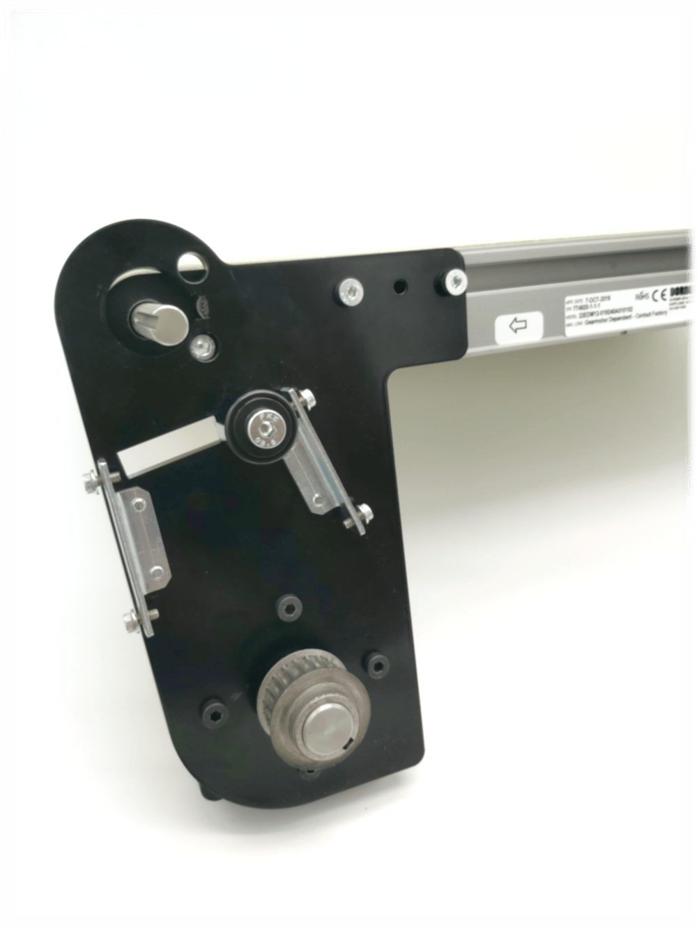
The motor mount and conveyor should look like this once the new fasteners are installed:
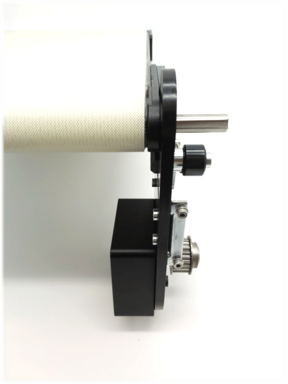
- Install the key into the keyway of the conveyor shaft, then slide the driven pulley onto the shaft and tighten the set screws to fix it in place. Ensure that the pulley is in-line with the idler and driving pulley so that the belt will track straight.
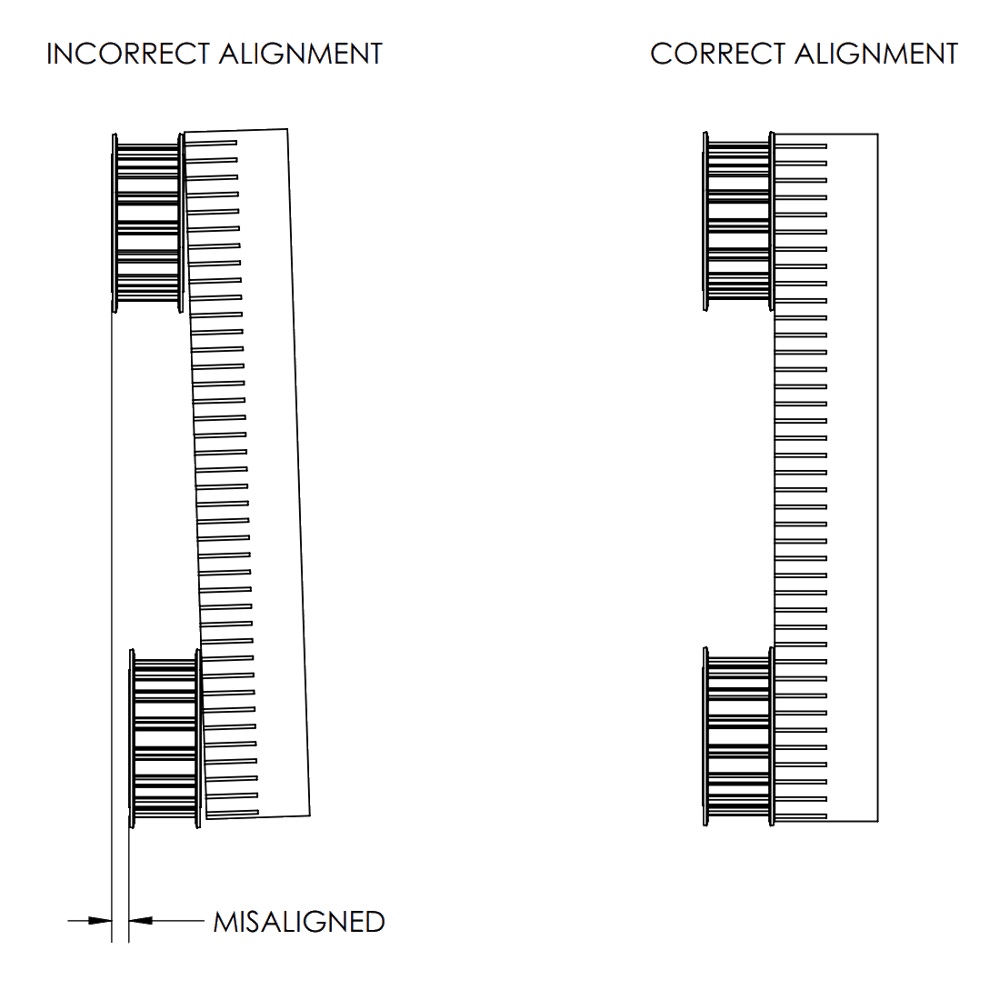
- Check that the pulleys are aligned with a straight edge. When the straight edge is placed across both pulleys, it should be perfectly parallel to the pulley side. If it is not, adjust the position of the pulley until it is aligned.
- Using the idler, apply tension to the belt so that the belt is tight enough so that 4.5N of force will cause the long section of the belt to deflect 3mm. Note the tensioner position should be driven by the main direction of travel of the conveyor. The idler should be on the slack side of the belt.
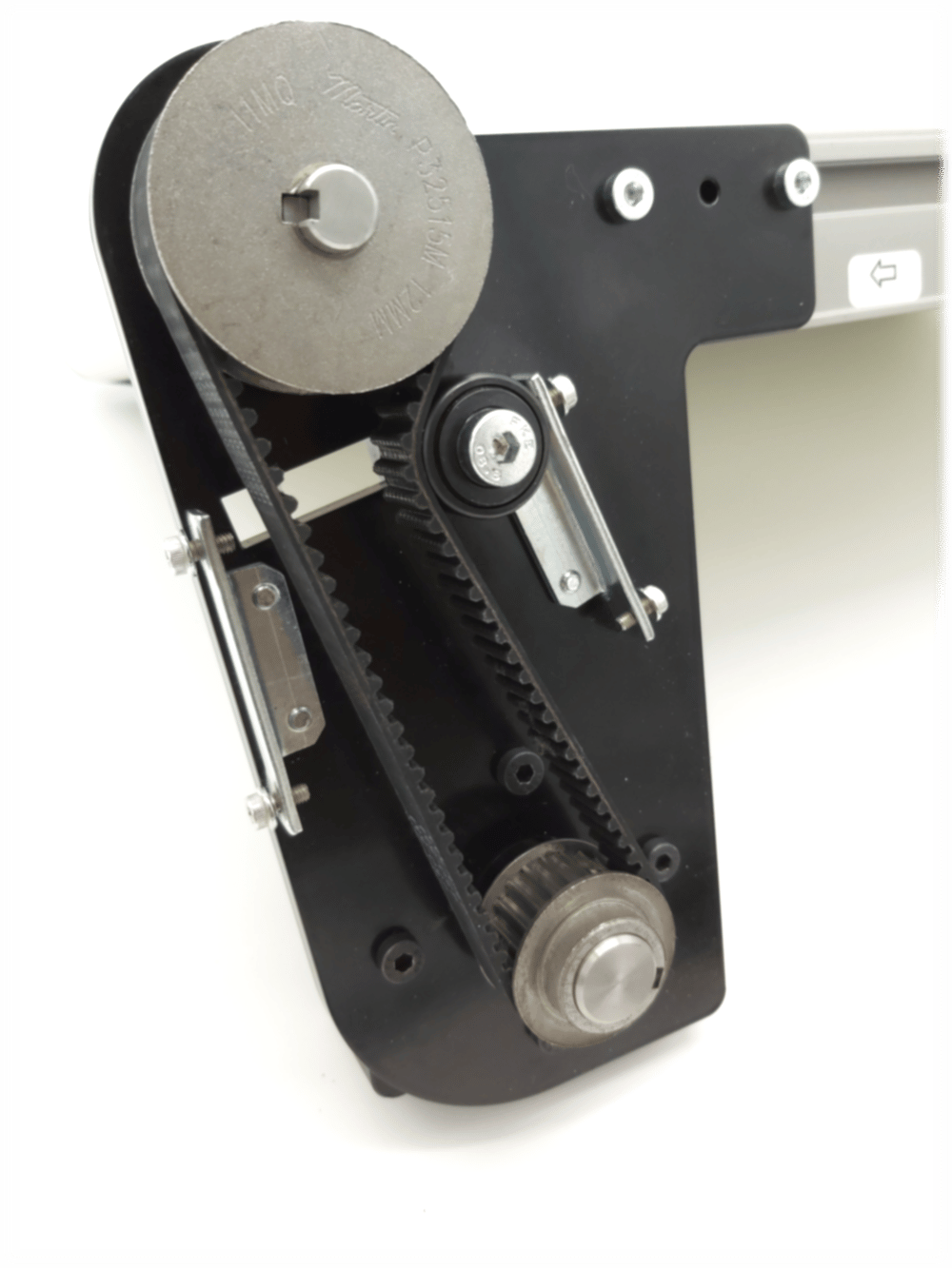
- Install the sheet metal cover using the 4x M4 fasteners.
- The following image shows the contents of the motor mount kit.
Transfer Plate
To line up our belted conveyors end to end and to allow for seamless transfer from conveyor to conveyor, one can install our transfer plates to the adjacent ends of the conveyors. The conveyors can then be lined up transfer plate to transfer plate. The transfer plate comes in four different sizes to fit each of our conveyor widths and allows for the transfer of products of a minimum length of 22 mm.
![]()
To install the transfer plate, simply remove the two countersunk M6 screws in the conveyor end plate, remove the protective plastic on the transfer plate, and place the transfer plate over the end plate. If you are installing the transfer plate on the drive side of the conveyor, place the transfer plate over the end plate before installing the motor mount. Subsequently, use the M6 socket head cap screws (5) that come with the motor mount to fasten the motor mount on top of the transfer plate.
![]()
Contrarily, if you are installing the plate on the end of the conveyor that doesn’t have the motor mount, fasten the transfer plate with the socket head cap screw and washers included with the plate.
![]()
Once you have your transfer plates installed on all your conveyors, you can go ahead and line up your conveyors transfer plate to transfer plate and transfer parts from one conveyor to the next.