Design guide
Updated: Wednesday, February 7e 2024
Design Review Checklist
MachineBuilder
Overview
This design review checklist is applicable for all non-automated equipment.
When you’re done putting your equipment together, walk away from it for at least a few hours (or sleep on it) so your mind is fresh for the design review. If you can’t spare the time, or you just want a second perspective, ask a colleague to review your work; we do peer reviews all the time here at Vention.
You can also get one of our Application Specialists to review your design. Just send a request through MachineBuilder’s assist toolbar or via live chat at the bottom-right of any Vention webpage.
Checklist
| 1. Frame Parts All frame parts present |
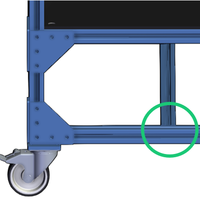
Starting from the bottom and working your way up, check for any missing extrusions, assembly plates , or other frame connector pieces. Pro tip: Go to the MachineBuilder settings toolbar (bottom) and select Visual Style > Hidden Lines to see extrusions connected end-to-end without an assembly plate. |
 |
| 2. Accessories All accessories present |
Working your way back down, look for missing frame accessories like handles, rest pads, levelling feet, monitor mounts, plastic end-caps, bumpers, and wear strips. | 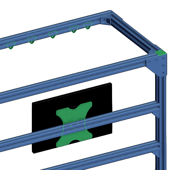 |
| 3. Assembly rigidity All frame connectors present and correctly squared. |
Check the outer corners of your design. There should be a frame connector on each of the three planes, and all extrusions should be tightly squared with each other. | 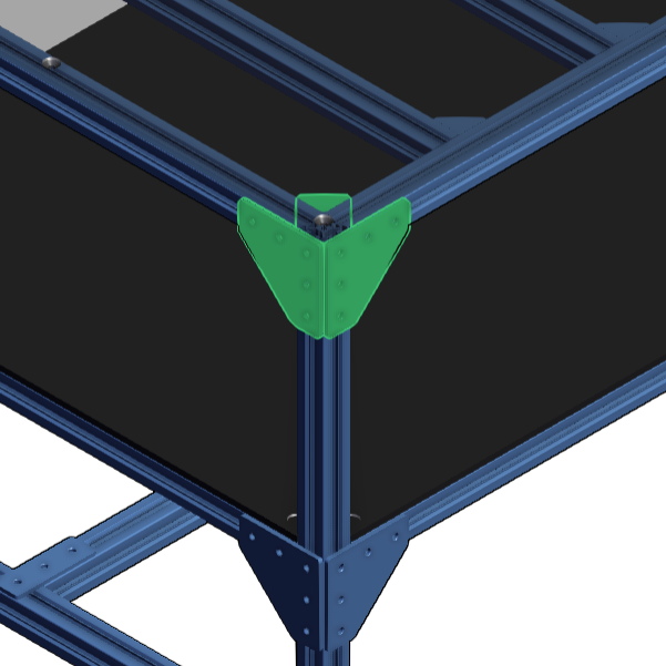 |
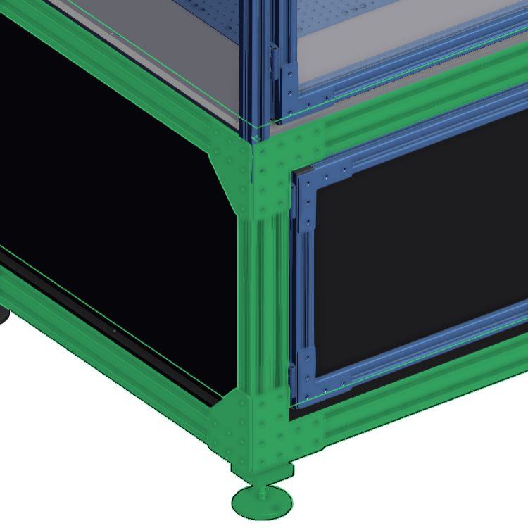
| 4. Structural integrity Base frame can support more than enough weight. |
Make sure your base frame is strong enough to hold whatever is on top of it. Pro tip: Use bigger aluminum extrusion profiles, like the 45 x 90 mm and 90 x 90 mm, to create your base. Use smaller profiles, like the 45 x 45 mm and 22.5 x 22.5 mm, to create the structure that goes on top of the base. |
 |
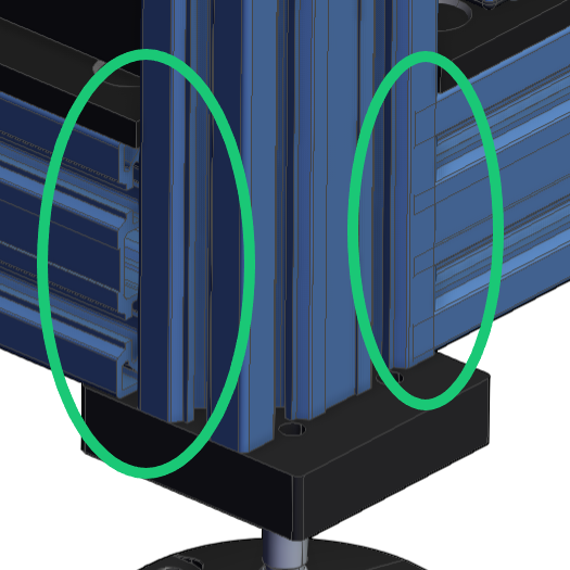
| 5. Frame interference Extrusion ends fit together—no gaps, no overlap. |
Take a closer look at the extrusion ends and make sure none of them are overlapping or gaping away from each other. Pro tip: To hide the assembly plates, hold Ctrl and select them one by one, then press Ctrl+H, and change the Visual Style to Shaded & Wireframe. This view makes it easier to spot interference. |
 |
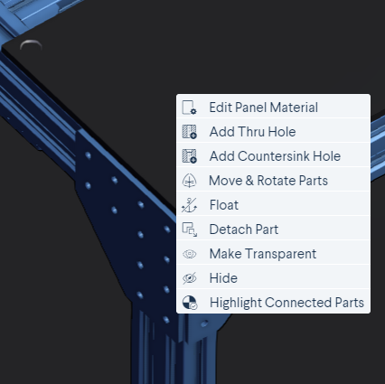
| 6. Panels All outside panels have thru holes or countersink holes. |
Make sure your “outside” panels have either thru holes or countersink holes. If any are missing, right-click on a panel to add the desired hole type. For help selecting the panels themselves, consult our guide to “choosing panel materials”. Pro tip: For applications subject to vibration, use panel strips or panel retainers on your “inside” panels. |
 |
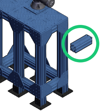
| 7. Part connections All parts connected. |
In the Navigation compass, select Float if your assembly is fixed. Move your design via drag-and-drop to identify non-connected parts. Pro tip: Press Ctrl+Z to undo your last move, then select Connection Checker. Try dragging and dropping your assembly again to confirm whether all connections issues have been resolved. |
 |
| 8. Hidden parts No hidden or duplicate parts. |
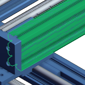
Find and delete any hidden or duplicate parts. When a part or panel has been duplicated and blends in with the original, visible hash lines will appear. Pro tip: Press CTRL+SHIFT+H to reveal all hidden parts. Alternatively, select Design Structure and search “hidden” to go through them one by one. |
 |
| 9. Frame connectors Optional (for high-precision assemblies): All assembly plates and frame connectors feature locators. |
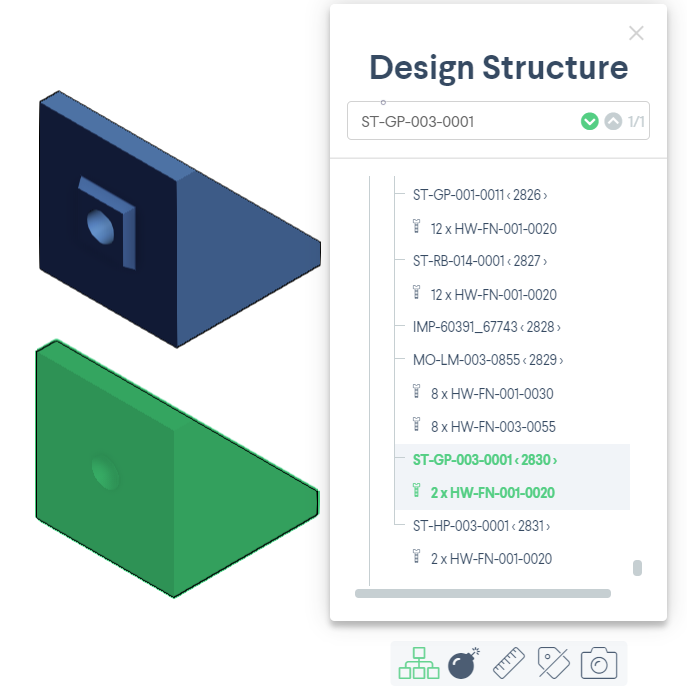
With joints that need greater rigidity and angular precision, be sure to use locators with your assembly plates and frame connectors. The HP in these parts’ names stands for high precision. For example, an HP gusset with locators adds rigidity and makes assembly easier. Pro tip: In the Design Structure tool, enter “ST-GP-003-0001” in the search bar to find regular gussets. If the gusset mates with t-slots on both of its faces, replace it with an HP gusset with locator ST-HP-003-0001. |
 |
| 10. Part consistency Same type of assembly joint components used throughout design. |
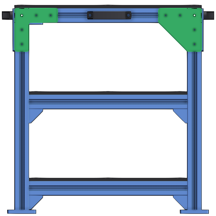
Check whether your structural and framing choices are consistent throughout your design. Assembly is easier when you use the same type of assembly joint components (assembly plates, gussets, and frame connectors) everywhere. |
 |
| 11. Stability Design is properly stabilized. |
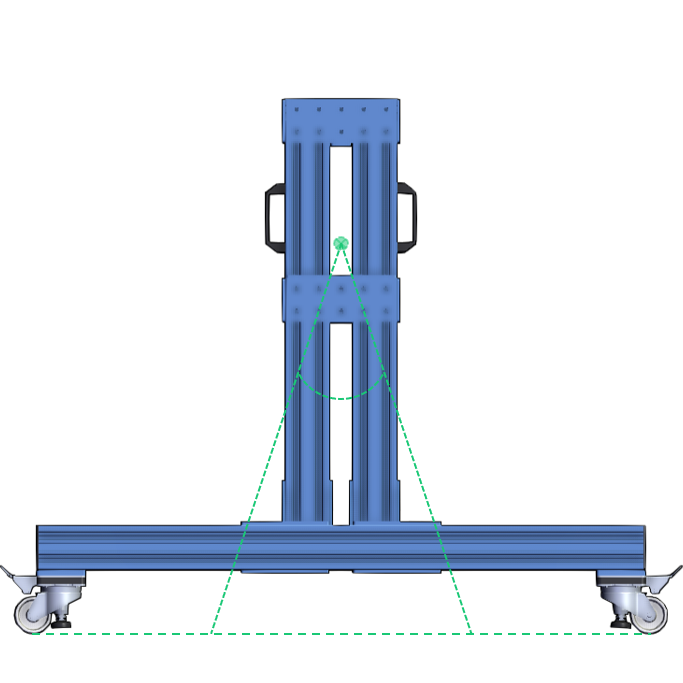
If your application is automated or your design supports a robot arm, your equipment must be anchored using the levelling feet or floor anchors. If the design is mobile, follow these guides to ensure stability: Equipment Stability and Robot Base Stability. Pro tip: In your design, plan for the heaviest equipment to be as close as possible to the floor. A lower center of mass will make the assembly more stable. |
 |
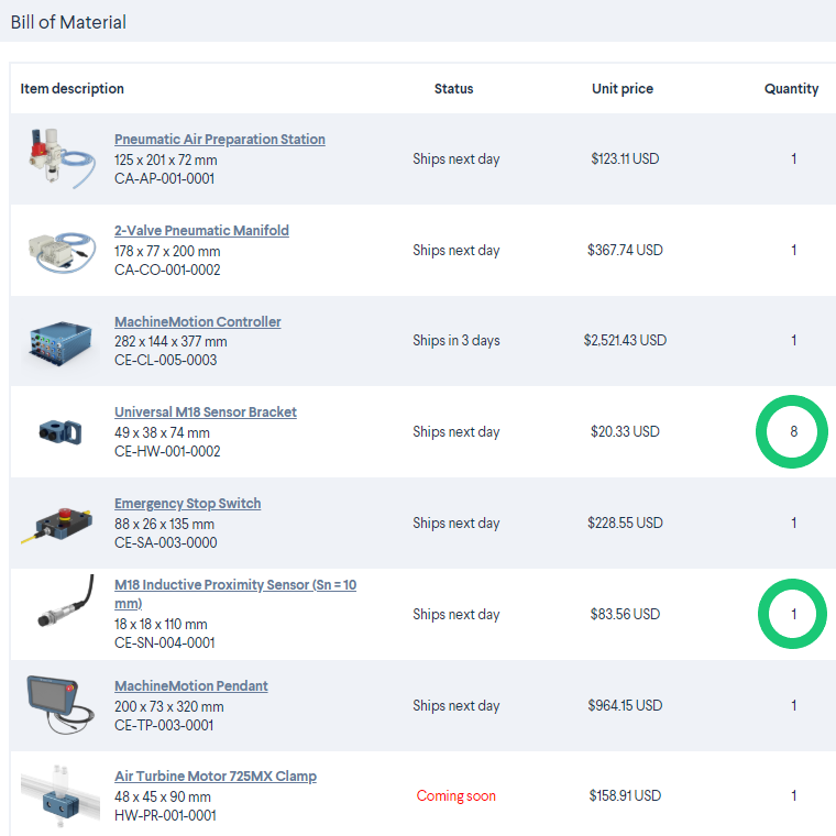
| 12. Bill of materials BOM includes all needed parts in correct quantities |
Select BOM and read it over one last time, to make sure you have included all the parts you need. Pro tip: Pay attention to any parts with a quantity of one, like a single caster wheel. You will likely need one for each corner of your base frame. |
 |
