Timing Belt Conveyor
Overview
The timing belt conveyor continues to grow Vention’s material handling portfolio, offering highly customizable possibilities with this simple, yet robust exposed timing belt actuator. Its design expands our 45 x 90mm extrusion ecosystem and is offered in multiple lengths and drive configurations tailored to your needs. Continue reading along this document to learn more about this new ecosystem of actuators as well as how to calculate the forces required to convey your goods and thus how to pair those requirements to the corresponding powertrain combinations.
Composition
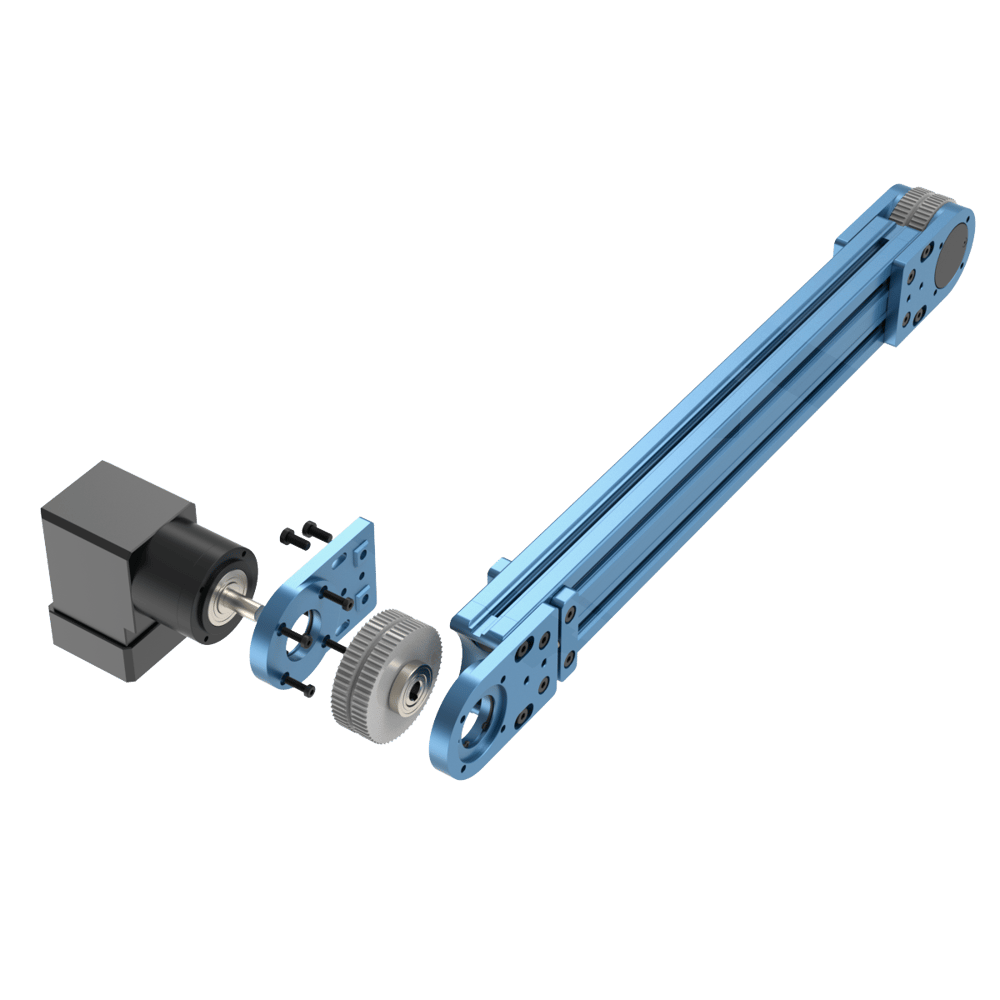
The timing belt conveyor is composed of the following parts:
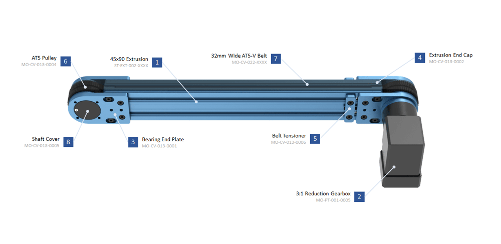
- At the core of this actuator is our 45x90mm V2 extrusion. This easily allows us to offer the actuator in multiple sizes and ensure modularity with the rest of the ecosystem.
- The 3:1 right-angle reduction gearbox is included with the powered timing belt conveyor for two reasons: to convert our NEMA 34 flange to a round flange, and to increase the driving force.
- The bearing end plate is used to support the pulley, shaft and bearing assemblies. It includes holes to mount the right-angle gearbox end to the end of the extrusion.
- The extrusion end caps serve as a precise locating feature for the bearing end plates but also serve to smooth out the transition from pulley to extrusion, reducing wear on the belt.
- The tensioner allows easy access for re-tensioning or belt removal purposes.
- The timing belt pulleys have full 180-degree belt engagement to ensure belt slip will not occur.
- The 32 mm-wide AT5 V-groove belt provides high-output force capacity, allowing the timing belt actuator to be used for light or heavy loads while maintaining good positioning accuracy.
- The pulley shaft cover protects the user from rotating shaft hazards.
Applications
The timing belt conveyor’s simple and robust design can accommodate a variety of material handling duties. One very popular use case for this new conveyor is metal pallet/tray handling. This type of operation is observed along assembly or packaging lines of industries (automotive, medical, consumer electronics, etc.). In the case of an assembly line, a subassembly or an assembly will sit atop a metal pallet/tray, which will slowly make its way along the assembly line, periodically pausing at different stations to have components added to it. To achieve this, we have released the timing belt conveyor along with pallet guiding accessories that will bring about another use case for our tooling plates, ST-SP-002-0003/0004. These accessories will be described further along this document.
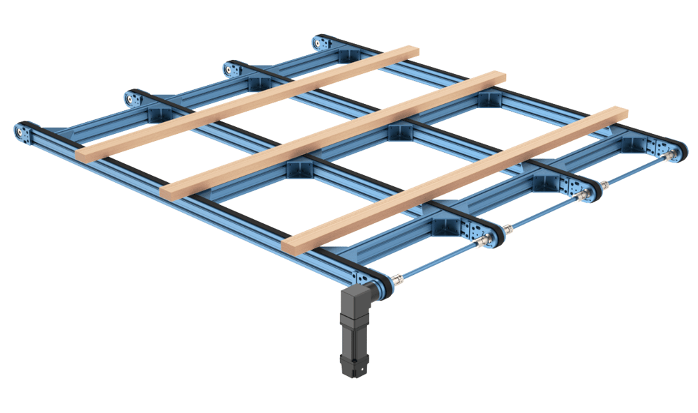
Another popular use case for this type of conveyor is handling long or large items such as dimensional lumber, sheets, panels, and plates of various materials. In these cases, these loads would be normally spread across a few timing belt conveyors, either independently powered, or linked via driveshaft.
Explore public designs to get ideas on how you could use the timing belt conveyor.
Technical Specifications
| Specification | Value |
|---|---|
| Rated Payload (kg)* | 75 |
| Displacement Ratio (mm/turn) | 100 |
| Force per unit of input torque (N / Nm) | 62.8 |
| Maximum input torque (Nm) | 36.6 |
| Max Speed (mm/s) | 2000 |
| Repeatability (mm)** | +- 1 |
| Belt Material | Polyurethane with tooth-side PAZ friction reduction coating |
| Gearbox Reduction Ratio | 3:1 |
*Rated payload is calculated over a pair of actuators.
**Measured over the actuator’s length, transitions are not considered, must be tensioned appropriately.
Available Sizes
The timing belt conveyor is available in 2 configurations: powered and unpowered. The powered segment includes the 3:1 right-angle reduction gearbox while the unpowered segment does not. The unpowered segment must be attached to a powered segment via a driveshaft coupler, discussed further below.
The table below provides the weight for each size of timing belt conveyor. For the total length of both actuators, add 223 mm to the extrusion lengths below.
| Part Number | MO-CV-013-XXXX | MO-CV-014-XXXX |
|---|---|---|
| 315 mm | 9.45 kg | 5.10 kg |
| 585 mm | 10.71 kg | 6.06 kg |
| 855 mm | 11.67 kg | 7.02 kg |
| 1530 mm | 13.94 kg | 8.99 kg |
| 2295 mm | 17.70 kg | 12.15 kg |
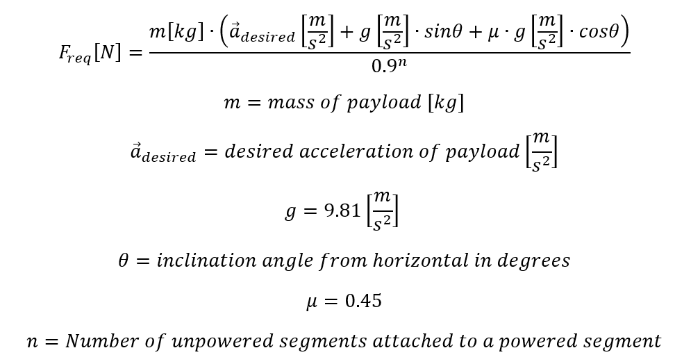
Calculating Driving Force
To calculate the required linear force to drive your payload a few things must be considered. Main considerations are the desired acceleration of the belt when starting, if the belt is on an incline or not, and what the friction generated by the payload is. The sum of these forces will give the required linear force of the belt conveyor.
Force vs. Speed
Output force indicates how much weight the actuator can move and how quickly it can accelerate. Once a driving force is calculated, you can then reference the following graph to see which motor curve intersects the driving force and if the sustained speed meets your application requirements.
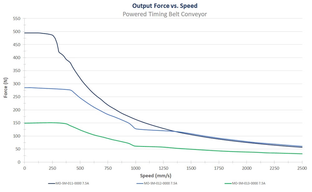
Note: These performance curves are made with our motors and controller at steady state conditions. Using others motors or controllers will have different behavior therefore performance and reliability cannot be guaranteed.
Assembly Instructions
The two configurations of timing belt conveyor actuator come completely assembled. All you need to do is install your choice of powertrain components, such as brakes, motors, and driveshaft couplers if power is being transferred to an unpowered segment.
Notes:
- When installing motors, apply a small amount of grease to the motor shaft so that it is lightly coated. This will reduce the possibility of fretting corrosion occurring during operation, making future removal easier.
- Moreover, do not use excessive force (hammering, prying or using screws to “push” the motor) to install the motor.
Powered Timing Belt Conveyor
Getting MO-CV-013-XXXX up and running is quite straightforward, it only involves the installation of your desired NEMA 34 stepper motor to the end of the 3:1 right-angle gearbox with the standard four M6 x 20mm fasteners. Be sure to tighten the clamping collar found on the input side of the gearbox prior to power-up. It can be accessed via the two black plastic caps, as is present on all our gearbox offerings.
Gearbox Orientation
If the clocking orientation of the gearbox of the as-shipped powered timing belt conveyor does not meet your application requirements, it can easily be rotated to three other positions, 90-degrees from one another. Follow the instructions below to adjust the orientation:
- Disassemble the four M8 bolts on both bearing plates.
- Loosen the M8 tensioner set screws evenly with a 4 mm Allen key.
- Remove the timing belt and set it aside.
- Fully loosen the M8 bolts on the bearing plate that the gearbox is attached to.
- Gently lift the bearing plate and pulley assembly up from the other bearing plate. The outer race of the bearing has a sliding fit with bore on the bearing plate so very little force will be required.
- Remove the pulley assembly from the gearbox-side bearing plate assembly, this too should require little force.
- The four M6 gearbox mounting bolts will now be exposed. Loosen them with a 4mm Allen key and re-orient the bearing plate as needed.
- To begin re-assembly, thread the M6 gearbox bolts back into the bearing plate, but do not fully tighten them as the bearing plate is likely not concentric with the gearbox shaft and pulley assembly.
- Slide the pulley assembly onto the gearbox shaft and seat the bearing in the bore by shifting the bearing plate as needed. Gently remove the pulley assembly while the bearing plate’s position, lightly tighten one M6 bolt.
- Re-install the pulley assembly and check for a sliding fit, if confirmed, remove it again and lightly tighten the remainder of the bolts.
- Re-install the pulley once more as a final check, if it is still easy to install, remove it and fully secure the four M6 bolts to 8 Nm.
- Complete the assembly by performing step 1-5 in reverse order, tension the belt according to the maintenance guide below.
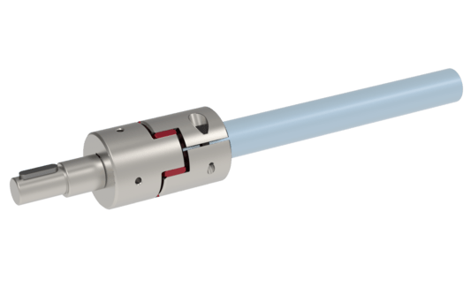
Unpowered Timing Belt Conveyor
Getting MO-CV-014-XXXX up and running requires the use of a pair of driveshaft couplers (MO-PT-005-0000) as well as an appropriately sized round extrusion (ST-EXT-008-XXXX) to transfer power from the powered segment to the unpowered segment. The driveshaft coupler permits for 22.5mm of round extrusion engagement on each coupler to maintain the 45mm increments for the round extrusion. To install the coupler on the round extrusion, simply loosen the clamping screw, seen as the black bolt in the image below, then insert the round extrusion to the appropriate depth, and re-tighten the clamping screw to secure it. It is possible that the shaft may be hard to slide into the coupler, in that case, with the screw loosened, the coupler can be wedged open a little further with a flat head screwdriver pushed into the slit, seen below as the small gap that the screw passes through.
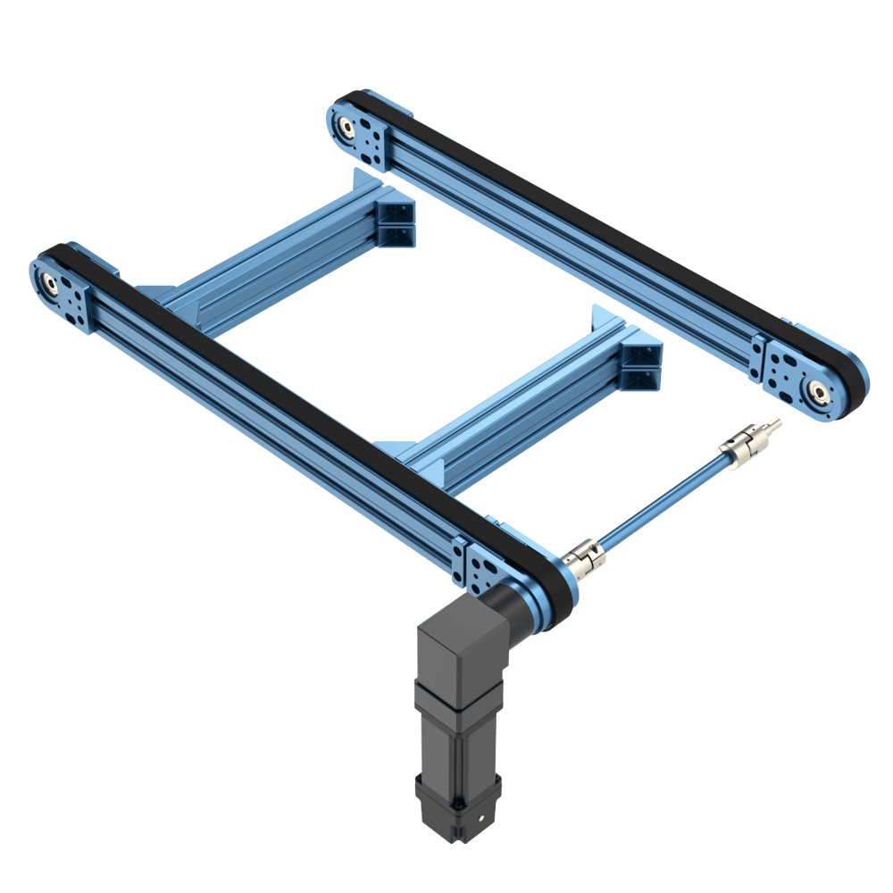
Some important tips:
- Be sure to perform a driving force calculation to validate how many unpowered segments can be attached to a single powered segment for your application.
- It is recommended that you build a “ladder-frame” style of support structure between timing belt conveyors. Prepare the powered segment with all cross-supports and driveshaft, to easily receive the unpowered segment as seen in the image below.
- The driveshaft couplers can only tolerate a very minute amount of misalignment, so care must be taken to dial out any major axial misalignment of the driveshaft between the powered and unpowered segments.
Pallet Guiding Accessories
A range of metal pallet/tray accessories were developed for the release of these new conveyors to bring new variety to our material handling capabilities in the form of assembly/packaging line conveying. All the accessories below are required to work in harmony with one another.
Tooling Plate Guides (MO-CV-013-0011)
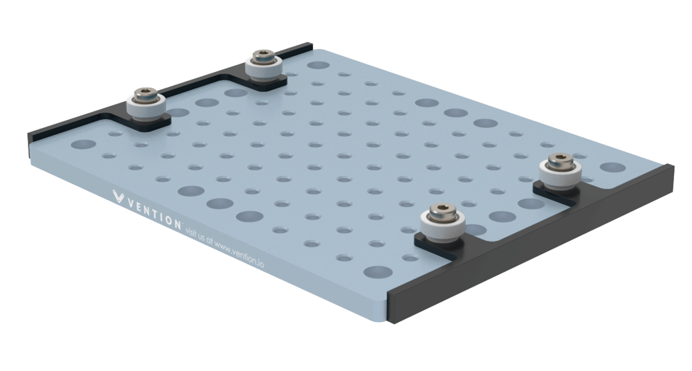
These Delrin guides allow the tooling plates to track straight while maintaining appropriate width spacing. The use of Delrin creates a durable wear and friction-reducing surface to prevent metal on metal contact. The provided bearings engage in the corner guide offering smooth direction changes by following a groove cut in the underside. The guides bolt to the threaded holes found on ST-SP-002-0003 and ST-SP-002-0004. A second set can be added to ST-SP-002-0004 if the tooling plate is only used along straight conveyor lines.
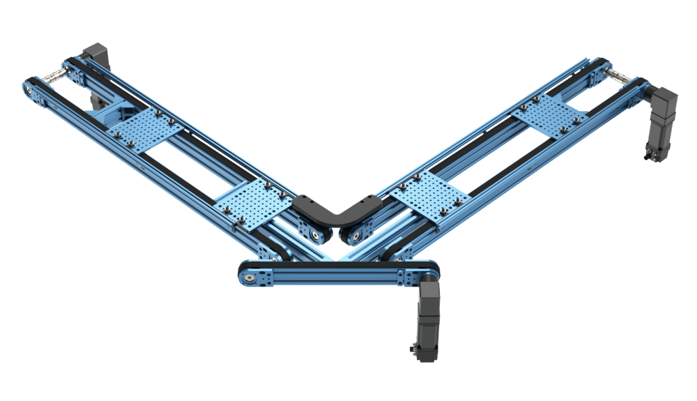
Right-Angle Turn (MO-CV-013-0007)
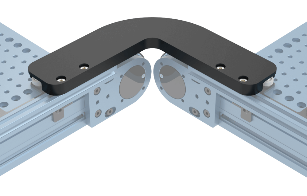
As its name suggests, this HDPE corner guide engages with the bearings of the pallet guides to smoothly change the direction of the pallet. The right-angle guide attaches atop the 22.5mm extrusion through the 4 counterbored holes.
Some important tips:
- Tuning of the corner guide’s position along the extrusion is advised to ensure that the arc traveled by the pallet is smooth and does not snag on any 22.5mm extrusion on both sides of the pallet.
- In order to complete a right-angle turn, a powered timing belt conveyor must be added 45 degrees to the incoming and outgoing line to smoothly move the pallet along its traveled arc.
- This transfer conveyor should be carefully leveled in respect to the incoming and outgoing lines to aid in smooth transition.
22.5mm Extrusion Guide Bracket (MO-CV-013-0008)
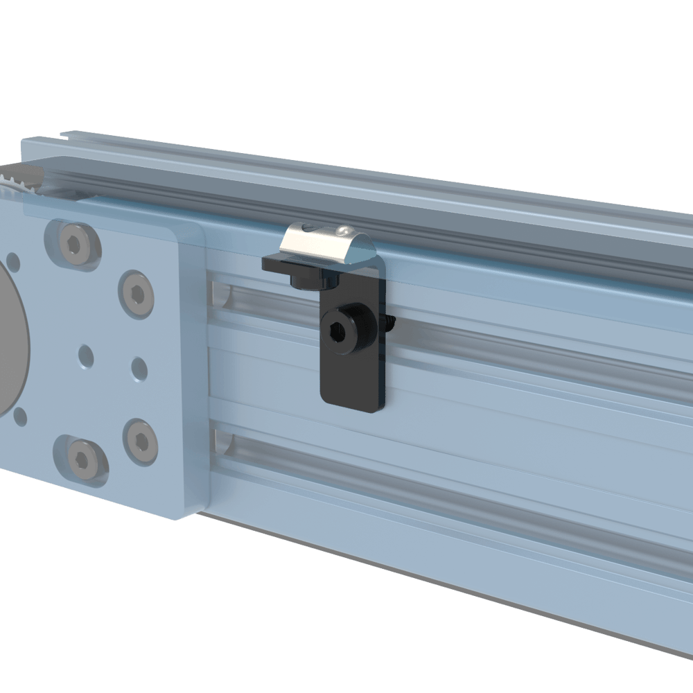
This bracket mounts to the side of the timing belt conveyor (long side) and supports the 22.5mm light-duty extrusion (short side). It is sized in accordance with the pallet and guides to ensure appropriate spacing and clearance.
As a baseline, we recommend the following minimum number of brackets per timing belt conveyor:
| Part Number | Number of Brackets |
|---|---|
| MO-CV-013/014-0315/0585/0855 | 2 |
| MO-CV-013/014-1530 | 3 |
| MO-CV-013/014-2295 | 4 |
Maintenance
The timing belt conveyors are very low-maintenance actuators.
Once monthly:
- Check of unusual noises
- Check belt tension
- Check for belt wear
- Clean the belt
To adjust the belt tension:
- Disassemble the four bolts on both bearing plates with a 5 mm Allen key.
- Begin tightening the M8 tensioner set screws evenly with a 4 mm Allen key.
- Pull on the belt in the middle of the span with about 1–2 kg of force. The belt should deflect no more than 10–15 mm. If it deflects much more than this, tighten the M8 set screws evenly.
- Re-tighten the four bolts on each bearing plate and torque to 10 Nm.