Datalogic Laser Scanner & Light Curtain User Manual
Overview
Safety devices are essential for a safe work environment. They can be used in various configurations to monitor safety zones where access is limited. Only one safety device (laser scanner or light curtains) can be connected to Vention’s Safety Module at a time. If you need to interface N number of safety devices to MachineMotion V2, you will need N number of safety modules (daisy-chained). Please refer to the Safety Module’s User Manual for more information about the connections.
Laser Scanner (Parent only)
Description
The Datalogic Laser Scanner (PR-DA-001-0489) is an essential tool to ensure safety in the workplace. It can be used in multiple orientations to monitor large areas while remaining discreet and unobstructive. It will stop a machine if any undesired person or object crosses its safety zone. It features a couple of useful functionalities such as muting; automatically deactivates the safety status of the whole system (total muting) or part of it (partial muting) to let material pass through. Another useful function is bank switching; ability to switch between two zone configuration (useful for muting two zones independently). A PC with an Ethernet port is required for configuration.
In order to use the Laser Scanner with MachineMotion2, a Safety Module (CE-SA-008-0000__2) is required, please refer to the safety installation guideline section for the wiring.
The Laser Scanner specifications are as follows:
- Maximum safe zone: 5.5 m radius.
- Maximum warning zone: 40 m radius.
- Detection angle: 275o.
- Total/partial dynamic muting available.
- Zone switching (bank switching) available.
- 12-pin M12 connector available for communication with Safety Module (CE-SA-008-0000__2).
- 4-pin M12 connector available for programming and monitoring (via an Ethernet cable to a computer).
Getting Started
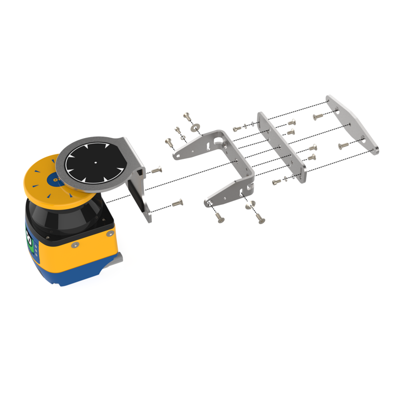
- Assemble the Laser Scanner bracket and mount it at the desired location.
- Download the latest version of the DL Sentinel software from here .
- Connect scanner to PC with the provided programming cable.
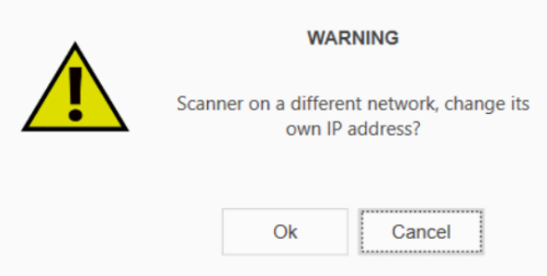
- On the PC, open the DLSentinel software, and navigate to Scanner > Discovery. Your scanner should appear on the left panel. Select your scanner. A warning window may appear asking to change your IP address. Select OK.
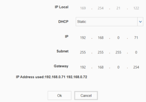
- Align the IP address. To align the IP address, make sure DHCP is set to Static. Verify that the last number of the IP Local address is different from the last number of the IP address. In figure 3, the last digits are 122 and 71, which are different.
- On the main screen of the DLSentinel software, select Open a Safety System configuration from PC. Open the initialization file and select the connected laser scanner from the panel on the left side of the screen
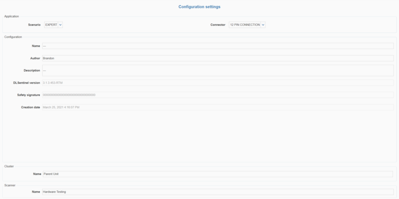
Parameters’ configuration
Perform the following steps to get access to the Configuration settings:
- Open the connected scanner in the DLSentinel software by navigating to Scanner > Discovery. The connected scanner will be visible in the left-hand column
- Select your scanner and click on the white arrow at the top-right corner of the screen
To set parameters, select Configuration to access a drop-down menu. For each item on the drop-down menu, enter the desired values in the appropriate fields (highlighted in yellow). More details are provided for each parameter below.
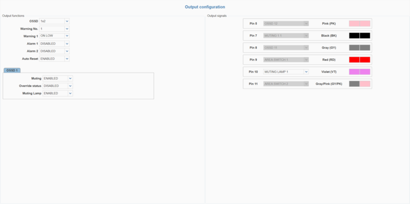
- Outputs:
- Auto Reset can be set to ENABLED or DISABLED. If the Laser Scanner boots with an error (such as both zones are activated, or no zones are activated), this function will automatically restart the Laser Scanner after 10 seconds. However, if the device locks in INTFx more than five times within 15 minutes (see Datalogic documentation for more details), Auto Reset will not activate, and a power cycle will be required to reactivate the device. It is recommended to set Auto Reset to ENABLED to avoid booting errors.
- Muting can be set to ENABLED or DISABLED. See Muting for more information
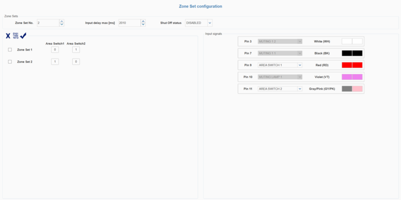
- Zone Set:
- Zone Set No. can be set to 1 or 2. Use two zones when independent muting of different areas is required (such as for a palletizer with two zones). When setting two zones, click the “01010” icon to automatically fill the area switch pin association.
- Zone Set 1 active when Area Switch 1 = 1 and Area Switch 2 = 0
- Zone Set 2 active when Area Switch 1 = 0 and Area Switch 2 = 1
For a two-zone configuration, 1 1 and 0 0 are invalid Area Switch combinations. This will result in an error state. To resolve it, provide a signal to either Area Switch 1 or Area Switch 2 (effectively creating a 1 0 or 0 1 combination) and restart the Area Scanner.
- Input delay max [ms] sets the allowable time delay between signals when switching zones. The minimum value (default) is 30 ms. Generally, this parameter is used to avoid delays between signal switching that could result in error states. A value of 510 ms is typically suitable for most devices. However, it is recommended to decrease this delay as much as possible according to the device/controller’s response time.
- Zone Set No. can be set to 1 or 2. Use two zones when independent muting of different areas is required (such as for a palletizer with two zones). When setting two zones, click the “01010” icon to automatically fill the area switch pin association.
- Inputs:
- Recovery time [msec] is the time delay between the object leaving the protected area and the OSSDs achieving the NORMAL OPERATION state. The minimum (default) value is 200 ms. It is recommended to keep the default value.
- Muting type can be set to bidirectional or unidirectional. Bidirectional muting allows for muting in both directions of motion (which generally requires four muting sensors). Unidirectional muting allows for muting in a single direction (which generally requires two sensors). See Muting for more information.
- M coeff. (for unidirectional muting only) is a multiplier of the time delay between the muting sensors. The range of this coefficient is an integer between 2 and 16 inclusive.
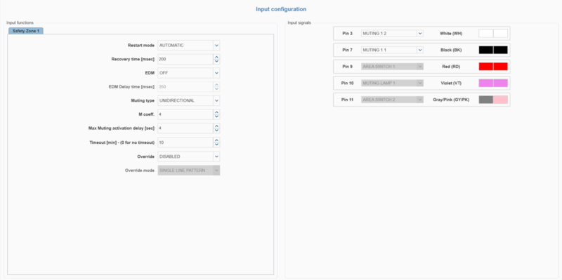
- Max Muting activation delay [sec] is the maximum allowable time between activation of the first muting sensor and the second muting sensor. The range of this value is an integer between 1 and 16 inclusive. For example, a palletizer with sensors spaced very close together at the entrance should have a max muting activation delay of 1–2 s, whereas the value for a simple roller conveyor application depends on the size and speed of the object moving.
- Timeout [min] is the maximum duration of a muting state before timing out. For no timeout, set this value to 0. The maximum value is 1080 minutes (18 hours).
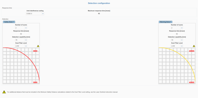
- Detection
- Number of scans controls the number of scans required to validate a detection. This parameter has a direct impact on Response time (more scans results in a longer response time).
- Detection capability [mm] is the ability to detect an object of given dimensions within the detection zone. Objects greater than or equal to the selected value can be detected in both the safety and warning zones.
- Dust Filter Level can be set to LOW, MID, or HIGH depending on the environment and the levels of airborne particles.Dust Filter Level should be set to the lowest value that still allows the Laser Scanner to work without detections due to dust.
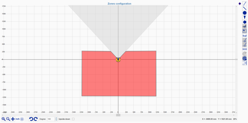
- Zones
- Select the appropriate zone (Zone 1 or Zone 2, if there are two zones) in which to create the safety, warning and muting zones.
- To create a warning zone, click Warning 1, select a drawing tool from the right side of the screen (freehand, line, circle, arc, or polygon) and draw the desired warning zone. Multiple areas can be defined. The defined warning zones will appear yellow.
- To create a safety zone, click Safety 1, and repeat the same procedure as above for warning zones. Safety zones will appear red.
- To create a muting zone, click Muting 1. A prompt will appear; select OK. The muting zone will be created over the entire safety zone (total muting) by default, and will be highlighted in blue. To define partial muting zones, delete the total muting zone (blue zone) and draw the desired partial-muting zone.
- To create a reference point, select the 6th icon down from the top right icons and place the point on a surface (such as a door frame or wall). Then set the tolerance. If the reference point moves outside the permitted tolerance, the OSSD will switch to an OFF state.
- NOTE: According to safety guidelines, when a laser scanner is monitoring a vertical plane, the safety zone should have a maximum gap of 180 mm from the bottom and a minimum height of 1400 mm when there are no height restrictions.
- Once satisfied with the configuration, click the Next white arrow in the top-right corner of the screen. Then click Load to upload the configuration to the area scanner. If prompted to enter a password, the default password is “admin” (this can be changed later). A warning will appear saying “Scanner status change in Off-Duty, continue?”. Select OK. Once the configuration is uploaded, click Accept to finalize the process.
- To ensure everything is working as expected, click Monitoring while plugged into the scanner to see a live feed of the scanner functioning.
For more information on various display icons that may appear on the Laser Scanner screen, refer to Datalogic’s Quick Guide for the SLS-M5-0812-E model.
Laser Scanner (Parent & Child Cluster)
Child Laser Scanner Description
The usage of Child Laser Scanners (PR-DA-001-0582) in combination with Parent Laser Scanners should be considered when the user wants to monitor multiple planes and/or areas that may be obstructed or not visible by a single Parent Laser Scanner. The Child Laser Scanner specifications are as follows:
- Maximum safe zone: 5.5m radius.
- Maximum warning zone: 40m radius.
- Detection angle: 275o.
- Total/partial dynamic muting available.
- Zone switching (bank switching) available.
- Daisy-chain cable included.
- The maximum number of units in a cluster is 4, consisting of 1 Parent Scanner and 3 Child Scanners.
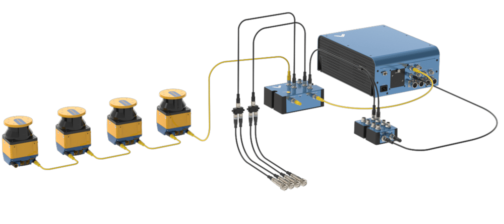
How to Configure a Parent-Child Cluster
To configure a laser scanner cluster comprised of a Parent Scanner and up to three Child Scanners, perform the following steps:
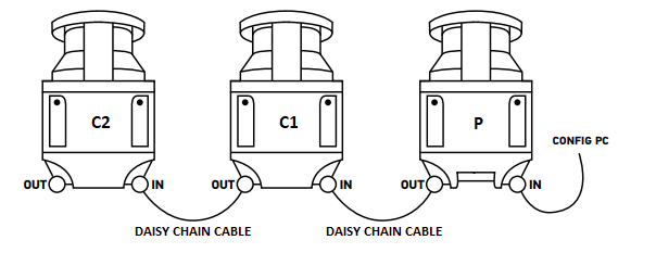
1. Connect the scanners as illustrated below using the included daisy-chain cables.
2. Follow steps 2 to 6 of the Getting started section for the Parent scanner.
3. Select the Parent Scanner on the left side of the DLSentinel window and click the white arrow at the top-right corner of the screen.
4. Configure the Parent Scanner using the Configuration drop-down menu located in the top-left corner of the screen. See the Parameters’ configuration section of the Parent Scanner for more information.
5. Select a Child Scanner on the left side of the DLSentinel window and click the white arrow at the top-right corner of the screen.
6. Under the Configuration drop-down menu, only configure the Detection and Zones items.
7. Repeat steps 5 and 6 for each Child Scanner in the cluster.
8. Once satisfied with the configuration, click the Next white arrow in the top-right corner of the screen. Then click Load to upload the configuration to the area scanner cluster. If prompted to enter a password, the default password is “admin” (this can be changed later). A warning will appear saying “Scanner status change in Off-Duty, continue?”. Select OK. Once the configuration is uploaded, click Accept to finalize the process.
9. To ensure everything is working as expected, click Monitoring while plugged into the scanner to see a live feed of the scanners functioning.
For more information on various display icons that may appear on the Laser Scanner screen, refer to Datalogic’s Quick Guide for the SLS-M5-0812-E (Parent Scanner) & SLS-R5-E (Child Scanner) models.
Troubleshooting
If the parent and the child scanners are not able to communicate to each other or cannot be configured together, make sure that they are all on the same firmware version.
If a child scanner is disconnected or missing from the cluster that has been programmed and uploaded, the parent scanner will fall into an endless power cycle loop. To solve this, either reconnect the missing scanner(s) or disconnect all children scanners and upload a parent-only configuration to the parent scanner (follow steps 2 to 6 in Getting started for the parent scanner) to regain access to the parent scanner. Then, reconnect the children scanners to the cluster and reconfigure the cluster as desired.
Light Curtain
Description
The Datalogic Light Curtain (PR-DA-001-0295 & PR-DA-001-0296) is a useful device to increase safety in various industrial applications. It is generally used to monitor and control the entry and/or exit of objects across a safety barrier. If an unwanted object or person crosses the safety barrier, the Light Curtain will stop the machine it is connected to. It also features total muting. In order to use the Light Curtain with MachineMotion2, a Safety Module (CE-SA-008-0000__2) is required, please refer to the installation instructions below.
The Light Curtain specifications are as follows:
- Resolution type: 4 (finger and hand protection).
- Resolution: 30 mm.
- Monitored height: 750 mm.
- Maximum operating distance: 20 m.
- Muting available.
Getting Started
- Choose an appropriate position for the light curtain, and mount both the emitter and the receiver with the connectors pointing in the same direction using the included mounting brackets.
- The light curtain should be carefully positioned to provide the necessary protection. Access to the dangerous area must only be possible by passing through the light curtain safety zone
Configuration - Disabling External Device Monitoring (EDM) for Rx Light Curtain Only
Before connecting the Light Curtain to the Safety Module and MachineMotion V2, make sure it is in the basic configuration. Follow the steps below to configure the Light Curtain.
Note: Use the associated tool tip provided to press the buttons.
- Keep the CONFIRM button pressed for 5 seconds to enter Basic Configuration Mode.
- A Test Pattern is shown on led interface; carefully check that ALL LED are lit in sequence from 2 to 8, then current configuration is shown.
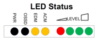
- Press SELECT until the ACM LED is BLINKING.
- Press ENABLE until the ACM LED is OFF.
- Press CONFIRM for 5 seconds to authorize the new configuration.
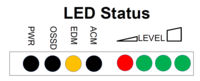
The LEDs on the light curtain should now be displayed as below.
Safety Installation guidelines
According to safety guidelines, a light curtain barrier should have a maximum gap of 180 mm from the bottom and a minimum height of 1400 mm when there are no height restrictions.
The same safety guidelines apply for a laser scanner mounted vertically (i.e. monitoring the vertical plane).
Connecting to MachineMotion 2
Laser Scanner
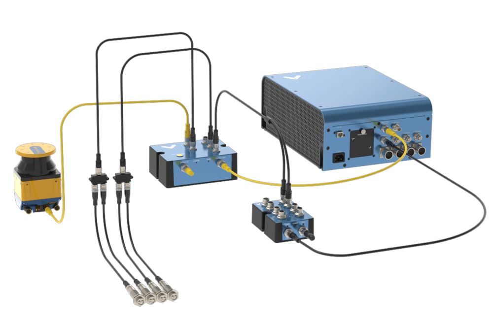
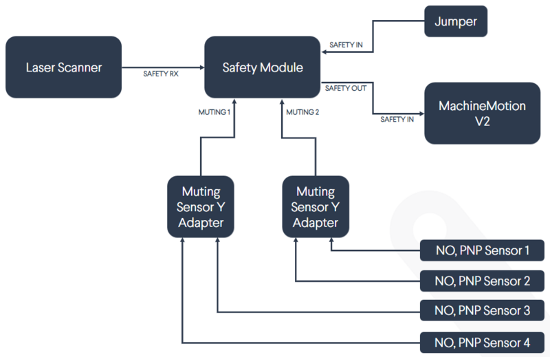
The steps to connect the Laser Scanner to MachineMotion 2 via the Safety Module are as follows:
- Connect the Laser Scanner to a Safety Module (CE-SA-008-0000__2) through the SAFETY RX connector using the Area Scanner Cable (CE-SA-104-0001)*.
- Connect a MachineMotion 2 Safety Extension Cable (CE-CA-102-5001) to the Safety Module’s SAFETY OUT connector and MachineMotion 2’s SAFETY IN connector.
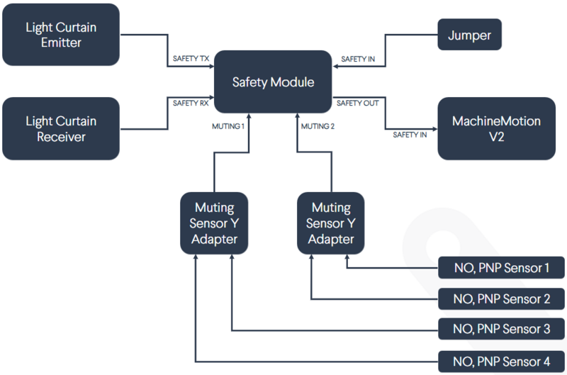
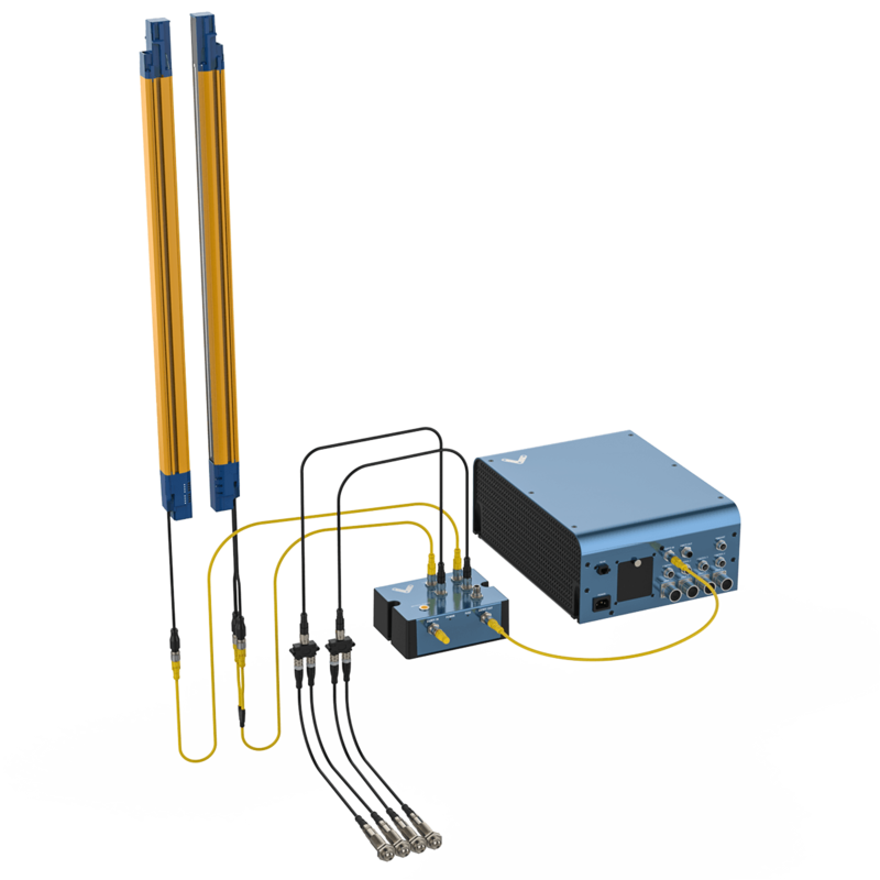
- If muting is required, connect the muting sensor in pairs to the Muting Sensor Y Adapter (CE-SA-107-0001). Then connect the adapter to the Safety Module via the MUTING 1 and/or MUTING 2 connectors.
- If bank switching is required, connect one end (1x M12-4 Female connector) of the Bank Switching Cable for Safety Module and DIOv2 (CE-CA-067-5000) to the CTRL IN connector on the Safety Module and the other end (2x M12-4 Female connectors) to outputs on the Digital IO V2 (CE-MD-001-0000__2).
*If a cluster of Parent-Child Scanners are being used, make sure to make all daisy-chain connections prior to connecting to MachineMotion 2.
Note: If no other safety devices are being daisy-chained to the Safety Module, a safety jumper (CE-SA-102-0001) must be used on the Safety Module’s SAFETY IN connector.
Light Curtain
The steps to connect the Light Curtain to MachineMotion 2 via the Safety Module are as follows:
- Connect the receiver to the SAFETY RX connector using the Light Curtain Receiver Cable (CE-SA-106-0001).
- Connect the emitter to the SAFETY TX connector using the Light Curtain Emitter Cable (CE-SA-105-0001).
- Connect a MachineMotion 2 Safety Extension Cable (CE-CA-102-5001) to the Safety Module’s SAFETY OUT connector and MachineMotion 2’s SAFETY IN connector.
- If muting is required, connect the muting sensor in pairs to the Muting Sensor Y Adapter (CE-SA-107-0001). Then connect the adapter to the Safety Module via the MUTING 1 and/or MUTING 2 connectors.
Note: If no other safety devices are being daisy-chained to the Safety Module, a safety jumper (CE-SA-102-0001) must be used on the Safety Module’s SAFETY IN connector.
Muting
The muting function automatically deactivates the safety status of the whole safety area (total muting) or part of it (partial muting). This feature is particularly suitable when an object, but not a person, has to pass through the dangerous area. This feature also allows carrying out cyclical operations without blocking a working machine.
Muting sensors must be placed according to the material’s length and speed so they can recognize passing objects (such as pallets, vehicles, etc). Generally, two muting sensors are used, and they must be triggered sequentially. It is also possible to use four muting sensors (where sensors A1 and A2 are connected together and B1 and B2 are connected together).
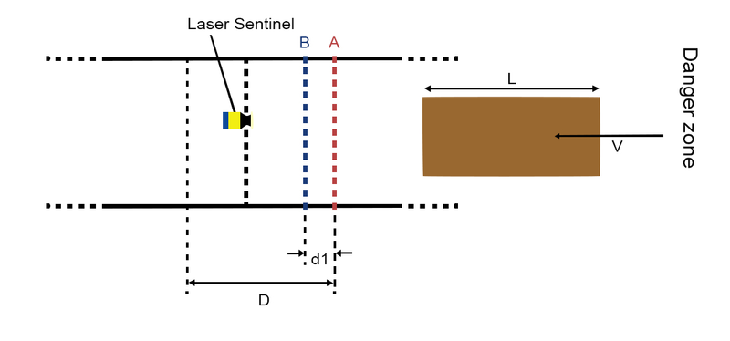
Unidirectional muting is used for objects entering or leaving an area. It requires two sensors, spaced at a distance slightly less than the length of the moving object, in order to detect undesirable objects with different dimensions or orientations.
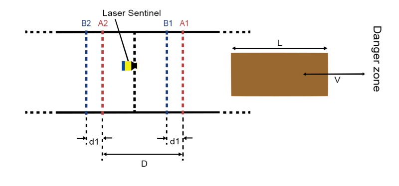
Bidirectional muting is used for objects entering and leaving an area. In this case, four sensors must be used: two on one side of the safe zone (A1 and B1), and two on the other side (A2 and B2). Sensors A1 and A2 are connected together, and B1 and B2 are connected together. They should be spaced at a distance where two consecutive sensors are always triggered throughout the movement of the object across the safety zone.
PNP Sensor Muting Configuration
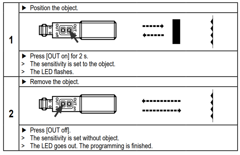
When muting with Vention Muting kit (CE-AP-002-0000), please use the procedure below to configure the PNP sensors.
Muting for Laser Scanner
The Laser Scanner can perform both unidirectional and bidirectional muting.
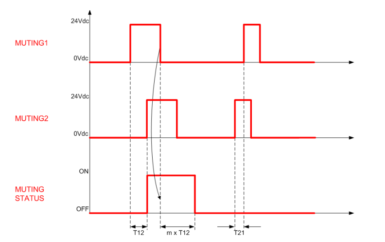
In unidirectional muting, the “m” coefficient must be defined. This coefficient controls how long the safety zone remains off before reactivating. In other words, it defines the activation time delay following a muting event.
The “m” coefficient is a multiple of the real delay between Muting 1 and Muting 2 (T12). The range of this coefficient is an integer between 2 and 16 inclusive.
Note: When muting is triggered, all defined muting zones in the active zone set configuration will be muted
Muting for Light Curtain
The Light Curtains can only perform bidirectional muting, which requires four sensors. Once muting is activated, the entire safety zone will be muted (total muting). Partial muting cannot be used with the Light Curtains.