Digital I/O Module User Manual
Contents
- Overview
- Features
- Included in the Box
- Physical Interface
- Status LED Indicators
- Resetting the electronic fuse
- Applications
- Setting the address configuration switches
- Configuring the Digital I/O Module v2 in Control Center
- Programming the Digital I/O Module v2 with MachineLogic
- Using the Digital I/O Module v2 with the Python API
Overview
The Digital I/O Module v2, CE-MD-001-0000__2, extends MachineMotion 2’s functionality with 4 (NPN or PNP) inputs and 4 PNP outputs. This plug-and-play module only requires a single connection to the MachineMotion 2 controller. Compatible modules, such as the Power Switch (CE-MD-005-0000) & additional Digital I/O Module v2 modules can also be daisy chained to each other, making it possible to connect up to eight modules per MachineMotion 2 controller.
Features
- 4 Inputs compatible with NPN and PNP sensors
- Connects (daisy chain) with compatible modules
- Configurable address
- Plug-and-play access from the Control Center, MachineLogic, and Python API
Included in the Box
| Part Number | Description | Quantity |
|---|---|---|
| CE-MD-001-0000__2 | Digital I/O Module v2 | 1 |
| CE-CA-022-5000 | Control Device Extension Cable, 5m | 1 |
| CE-JP-001-0001 | Module Termination Jumper | 1 |
| HW-FN-003-0018 | M8 x 18-mm Screw | 2 |
| HW-FN-002-0001 | M8 Drop-in Spring-Loaded T-Nut | 2 |
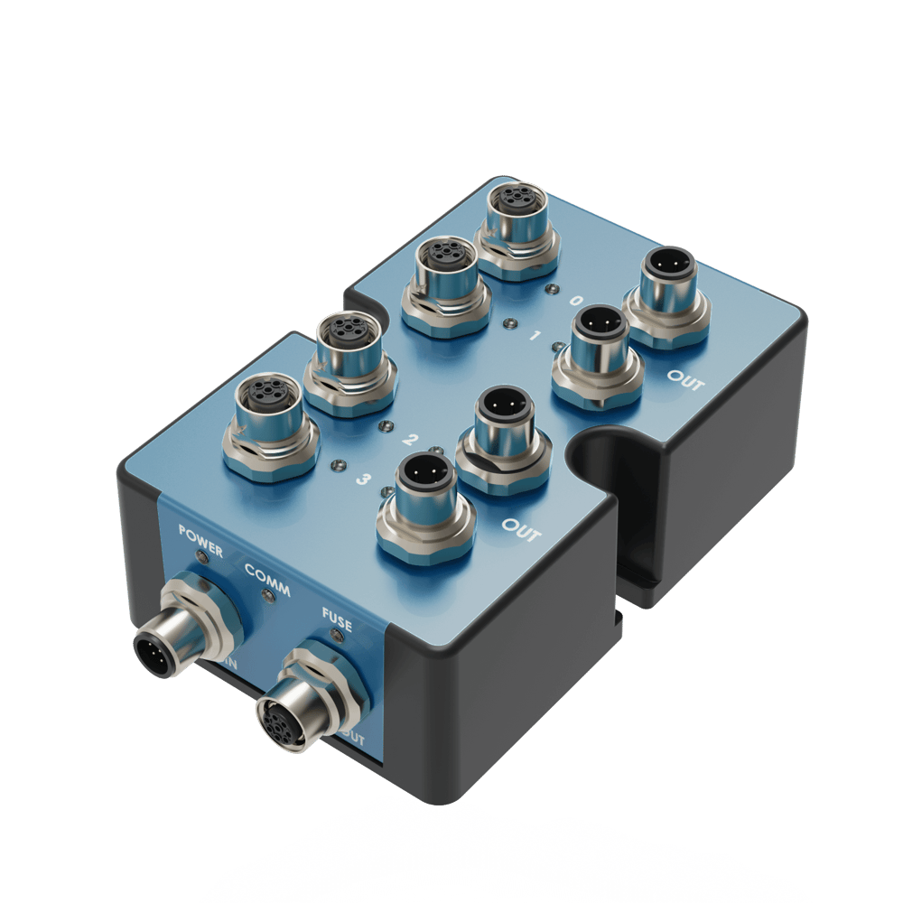
Physical Interface
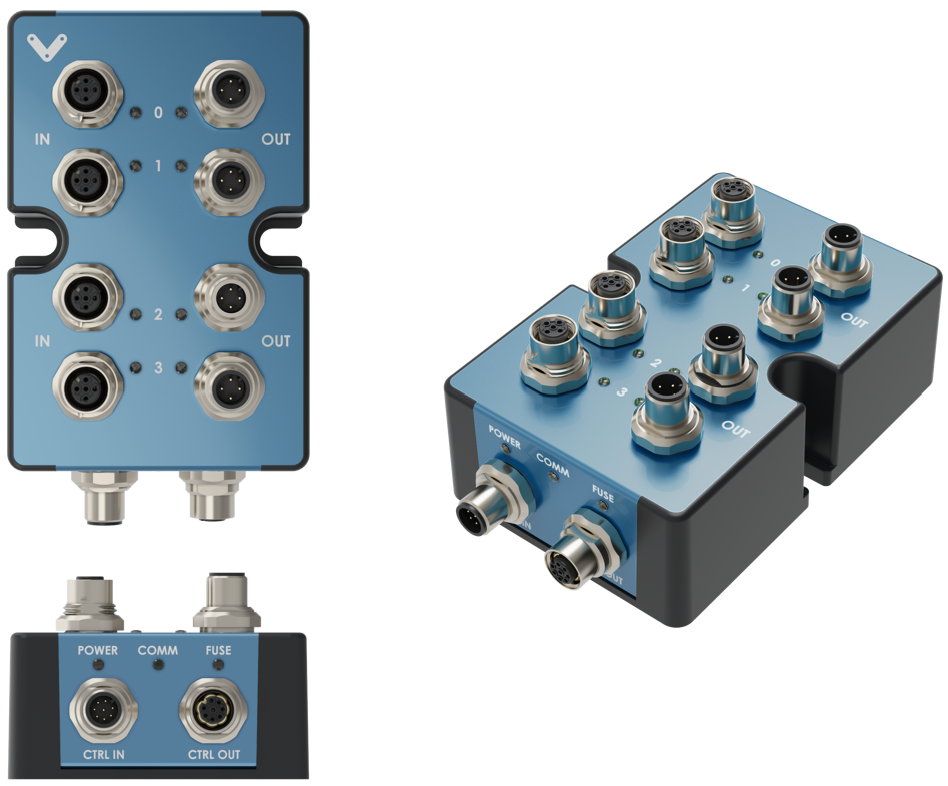
Status LED Indicators
| Name | LED Color | Indicated (when ON) |
|---|---|---|
| POWER | White | 24 VDC supplied to module |
| COMM | Yellow and Blue | RS-485 communication functional |
| FUSE | Red | Module internal fuse tripped |
| STATUS LED - OUT | White | Active (24V) |
| STATUS LED - IN | White | Active (24V or 0V) |
Resetting the electronic fuse
The Digital I/O Module v2 has an internal resettable electronic fuse that will trip in case of a short-circuit between the power pins (24V and 0V). This may occur when connecting a faulty or miswired device to the module, or even by touching pin #1 and pin #3 of any digital input/output port with a metallic object. If the fuse trips on a given module, the FUSE status LED will turn on red, but modules connected on the same daisychain will not be affected since each of them has its own fuse. To reset the fuse, simply disconnect and reconnect the cable on the CTRL IN port.
Applications
Connecting to MachineMotion 2 (directly)
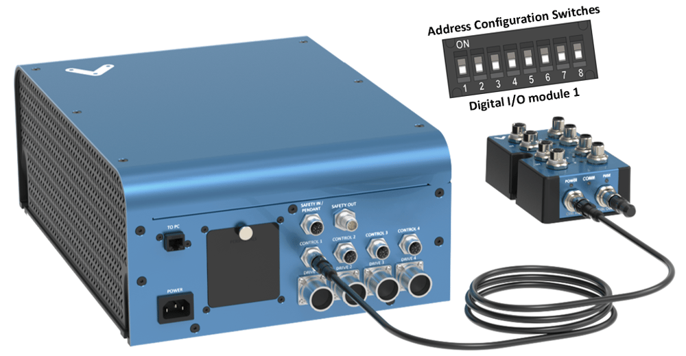
To connect a Digital I/O Module v2 directly to MachineMotion 2 (see Figure 2):
- Set the address of the Digital I/O Module v2, as explained in the Setting the address configuration switches section below.
- Using the Control Device Extension Cable (CE-CA-022-5000):
- Connect the male end to any CONTROL port on MachineMotion 2.
- Connect the female end to the CTRL IN port on the Digital I/O Module v2.
- Connect the Module Termination Jumper (CE-JP-001-0001), to the CTRL OUT port on the Digital I/O Module v2.
Connecting to MachineMotion 2 (daisy chain)

Compatible modules, including the Digital I/O Module v2 can also be connected via daisy chain to a single CONTROL port on the MachineMotion 2 controller (see Figure 3). Across all four CONTROL ports, the controller supports up to eight modules at the same time, provided they all have distinct addresses (see Address configuration switches).
To connect several modules in a daisy chain:
- Set a distinct address for every module of the daisy chain, as explained in the section Setting the address configuration switches.
- Using a Control Device Extension Cable (CE-CA-022-5000):
- Connect the male end to any CONTROL port on MachineMotion 2.
- Connect the female end to the CTRL IN port on the first module of the daisy chain.
- For every additional module to be connected in the daisy chain, repeat this step using an additional Control Device Extension Cable (CE-CA-022-5000):
- Connect the male end to the CTRL OUT port on the previous module in the daisy chain.
- Connect the female end to the CTRL IN port on the current module in the daisy chain.
- Connect the Module Termination Jumper (CE-JP-001-0001), to the CTRL OUT port on the last module in the daisy chain.
Connecting non-Vention components as digital inputs/outputs
While every Vention component (sensors, pneumatic manifolds, etc.) is compatible with the Digital I/O Module v2 out-of-the-box, other external devices can also be easily connected to the module.
To connect a non-Vention device as a digital input (e.g. sensors, switches, etc.):
- The signal can be either NPN (sinking, active 0V) or PNP (sourcing, active 24V).
- If the device uses a M12, 4-pin, A-keyed, male interface with the signal on pin #2, you can connect it directly to any module input.
- If the device does not use such interface or if the signal is on a different pin, use field-wireable male connector adapter CE-CN-030-0001 with the pinout shown below.
| Digital Input Pin | Description |
|---|---|
| Pin 1 | 24 VDC |
| Pin 2 | Input |
| Pin 3 | Ground |
| Pin 4 | Not Connected |
To connect a non-Vention device as a digital output (e.g. valve, relay, LED, etc.):
- The activating signal has to be PNP, operate at 24V and consume no more than 100mA.
- If the device uses a M12, 4-pin, A-keyed, female interface with the signal on pin #2, you can connect it directly to any module output.
- If the device does not use such interface or if the signal is on a different pin, use field-wireable female connector adapter CE-CN-048-0002 with the pinout shown below.
| Digital Output Pin | Description |
|---|---|
| Pin 1 | 24 VDC |
| Pin 2 | Output |
| Pin 3 | Ground |
| Pin 4 | Not Connected |
Setting the address configuration switches
Each module has an address with two components: device ID and device type. Both device ID and device type are set by changing the state of the address configuration switches, which are located at the back of the Digital I/O Module v2 under a removable rubber cap.
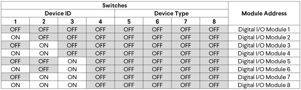
Switches 1 to 4 define the module device ID and allow the MachineMotion 2 controller to know which module it is communicating with. Every module connected to the same controller should have a distinct device ID, regardless of its device type.
Switches 5 to 8 define the module device type and their positions should remain identical for all modules of the same type.
The table below lists every valid address for the Digital I/O Module v2. An individual switch is considered ON when the selector is slid up and OFF when the selector is slid down.
Configuring the Digital I/O Module v2 in Control Center
If you would like to configure your Digital I/O module v2 and utilize MachineLogic to program your Digital I/O module, v2 follow the steps below:
- Open the Control Center on a PC (by entering 192.168.7.2 in the Google Chrome URL) or use the MachineMotion 2 Pendant.
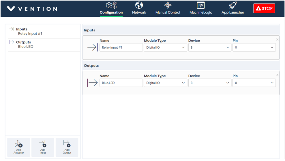
- Go to the Configuration tab and click Add Input.
- Fill out the following fields:
- Name: Give your Digital I/O module v2 a friendly name, which will be used to call the Digital I/O module v2 in MachineLogic
- Module Type: In the drop-down menu, select Digital IO
- Device: Represents the device ID of your module. The device number is configured on the physical module using dip-switches, therefore, ensure the device ID configured in this dropdown matches the dip switches configured on the physical device.
- Pin: Select the pin that you would like to control.
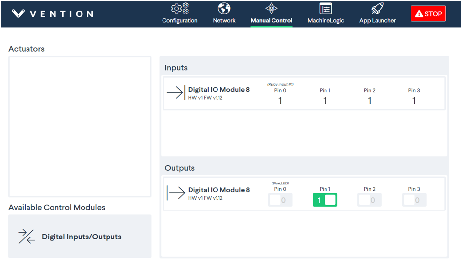
- To test the configured Digital I/O, go to the Manual Control tab and navigate to the Digital Inputs/Outputs at the bottom left of the screen.
- Under Inputs, you should see your configured Digital I/O modules v2:
Programming the Digital I/O Module v2 with MachineLogic
To program your Digital I/O module v2 in MachineLogic, ensure you have completed the steps in Configuring the Digital I/O Module v2 in Control Center.
- Go to the MachineLogic tab.
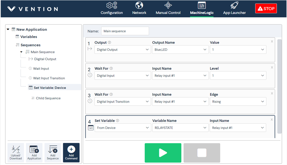
- Click Add command > Add Output:
- Under Output, selecting Digital Output
- Under Output Name select your device
- Under Value, select the state that you would like your device to be in
- Click Add command > Add Wait:
- Under Wait For, selecting Digital Input Transition would allow your program to wait for a Digital input rising edge or falling edge before playing the next command.
- Click Add command > Add Wait:
- Under Wait For, selecting Digital Input would allow your program to wait for a Digital input to be 0 or 1 before playing the next command.
- It is also possible to get the state of the Digital Input into a Variable.
Using the Digital I/O Module v2 with the Python API
See Python API reference here