Not all t-slot extrusions are the same. Very few have been designed from the ground up for today’s cobot and modular automation needs. But extrusion quality is only half the story. Getting a consistent level of performance demands a deeper understanding of the mechanical properties that govern the structural behavior and design practices that maximizes rigidity. Validating the architectural choices you make is equally important.
This guide is for engineers and automation designers who need a rigorous framework for specifying, assembling, and validating aluminum extrusion structures.
Why Early T-Slot Systems Fell Short on Rigidity
T-slot aluminum extrusions have been around for decades, but three well-documented problems historically limited their use in serious industrial applications. The first was rigidity. The T-slot groove cut into each extrusion face removes material from the cross-section, reducing the profile’s moment of inertia and producing lower strength-to-weight ratios than solid square tubing.
The second was assembly tolerance. Standard assembly relied on T-slot bolts as the locating device between plates and extrusions. The clearance fit introduced angular misalignment of up to +/-0.50mm per 25mm length. This fit also caused T-nut slippage under heavy loads, creating non-linear structural behavior that made failure difficult to predict.
The third problem is gradual loosening of the assembly joints, which required periodic re-torquing of the screws. The first two problems have since been addressed through better profile geometry, improved alloys, and precision interface systems. Vention’s patented extrusion system with 5x better vibration resistance has completely resolved the third challenge, eliminating the need for frequent re-torquing.
Core Mechanical Specifications: What Actually Governs Rigidity and Strength
To understand how a profile will perform, you must separate rigidity (resistance to flexing) from strength (resistance to permanent bending or breaking). The following properties determine whether a profile will perform as designed.
Area Moment of Inertia

The area moment of inertia describes a profile’s resistance to beam bending. A higher value means less deflection under the same load. It is the most important property for horizontal spans and gantry beams.
Orientation matters here. A 45x90mm extrusion performs very differently depending on whether the long face is vertical or horizontal relative to the applied load.
Profile geometry also matters more than outer dimensions suggest. Across five competing 45x45mm profiles, area moment of inertia values ranged from 107,780 mm4 to 162,325 mm4, a 50% spread that translates directly to differences in deflection under identical loads.
Test your profile: The Deflection Calculator lets you compare deflection and stress across profiles before committing to a purchase.
Cross-Sectional Area

Cross-sectional area governs a profile’s capacity to resist axial forces of compression and tension along its length. It also correlates directly with weight and cost, so increases come with a material penalty.
Torsional Constant

The torsional constant (J) measures resistance to twisting along the profile’s axis. This matters most in applications where load is applied at a distance from the support point: extended cantilevers, robotic arm bases, and XYZ gantry framing. In benchmarking data for 45x45mm profiles, torsional constant values ranged from 19,394 mm4 to 39,719 mm4, a 2x spread that makes a significant difference in robotic and dynamic applications.
Yield Strength & Modulus of Elasticity
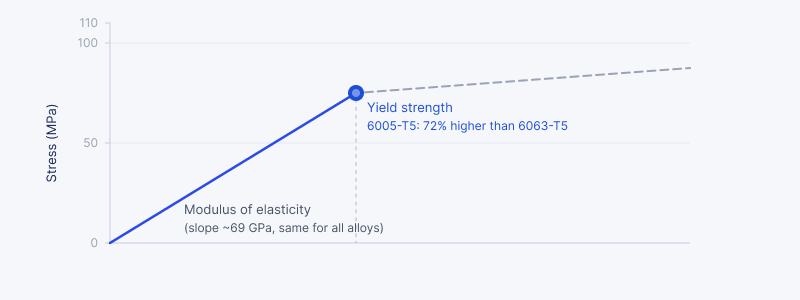
Modulus of elasticity represents the slope of the stress-strain curve in the elastic region and measures how much a material resists deformation under load. For aluminum alloys, this value is consistent at ~69 GPa regardless of alloy, meaning rigidity is primarily a function of profile geometry rather than alloy choice.
Yield strength is where alloy selection becomes critical. It’s the stress level at which aluminum permanently deforms, setting the upper limit for safe load capacity and serving as the baseline for safety factor calculations. While it has no bearing on rigidity, it governs strength entirely. Two geometrically identical profiles with different alloys will have meaningfully different load limits. For instance, 6005-T5 aluminum, used in Vention’s extrusions, has a 72% higher yield strength than the 6063-T5 profiles.
Vibration Resistance
In dynamic environments, vibration gradually loosens fasteners at structural joints. A frame that is properly spec’d for rigidity and strength can still develop play over time if this is not accounted for during design. While Vention extrusions deliver 5x more vibration resistance than traditional systems, that advantage is only fully realized when joints are secured correctly.
The fix is straightforward: use mechanical or adhesive anti-vibration solutions at your joints. For most applications, Nordlock washers are the right choice. Their wedge-locking design increases fastener preload under any loosening force, making them highly resistant to vibration without adding complexity to assembly. If your design includes counterbores where fastener head protrusion is unacceptable, Loctite 263 is the best adhesive alternative. It works on aluminum without a primer and delivers comparable holding performance.
Avoid nylok-treated T-nuts and zinc-plated fasteners in vibration-prone applications. Both performed poorly under accelerated testing and introduce installation challenges that compound the problem.
High-Rigidity Design Practices
Knowing the mechanical properties is the starting point. Applying them in a real assembly requires a few additional design principles.
Use the Moment of Inertia-to-Surface-Area Ratio as Your Primary Selection Metric
When comparing profiles, the area moment of inertia divided by cross-sectional surface area is the most useful single metric. A high ratio means more bending resistance per unit of material.
Across five competing 45x45mm profiles, this ratio ranged from 184 mm2 to 213 mm2. The highest-performing profile also produced the lowest deflection: 5.58mm on a 500mm cantilever at 1,500 N, versus 8.28mm for the weakest. Vention’s extrusions achieve this through a double-arm design that moves material from the profile’s center toward the outer walls, where it contributes most to stiffness.
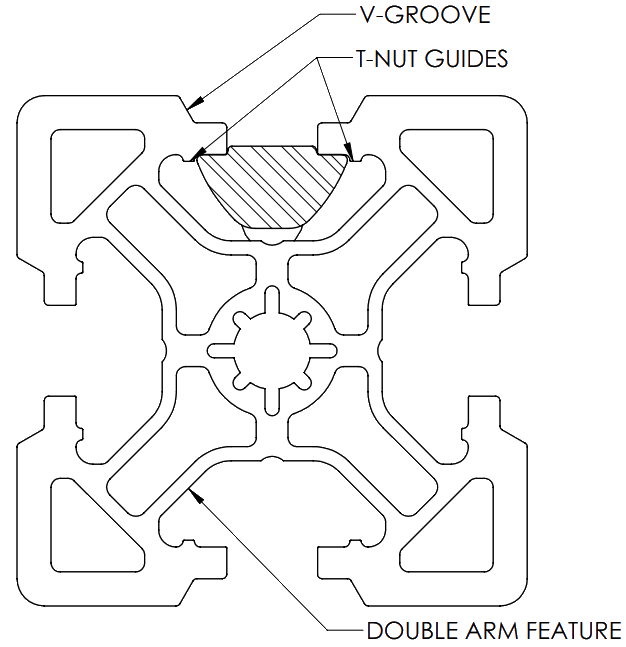
Use Self-Aligning Interface Systems for Precision Applications
Traditional T-slot assembly uses the bolt as the locating device. The clearance fit required for installation introduces misalignment that compounds across multiple joints.
Vention’s patented V-shaped groove interface (USPTO #10,662,650) systems address this at the design level. A V-shaped feature extruded into the T-slot acts as a part locator, and the corresponding assembly plate includes a matching male locator, constraining the joint mechanically rather than relying on fastener tightening alone. Vention’s implementation of this system means each assembly node carries up to 25% more payload than nodes without V-shaped grooves.
The practical result is an angular error of less than +/-0.04mm per 25mm length, compared to the +/-0.50mm typical of clearance-fit systems. For robot bases and motion systems where alignment errors accumulate across joints, this directly affects repeatability and long-term structural integrity.
Some extrusions also add guiding edges along their length, forcing T-nuts into the correct position automatically during assembly. Vention’s extrusions include this across all profile sizes, reducing positioning errors without additional tooling.
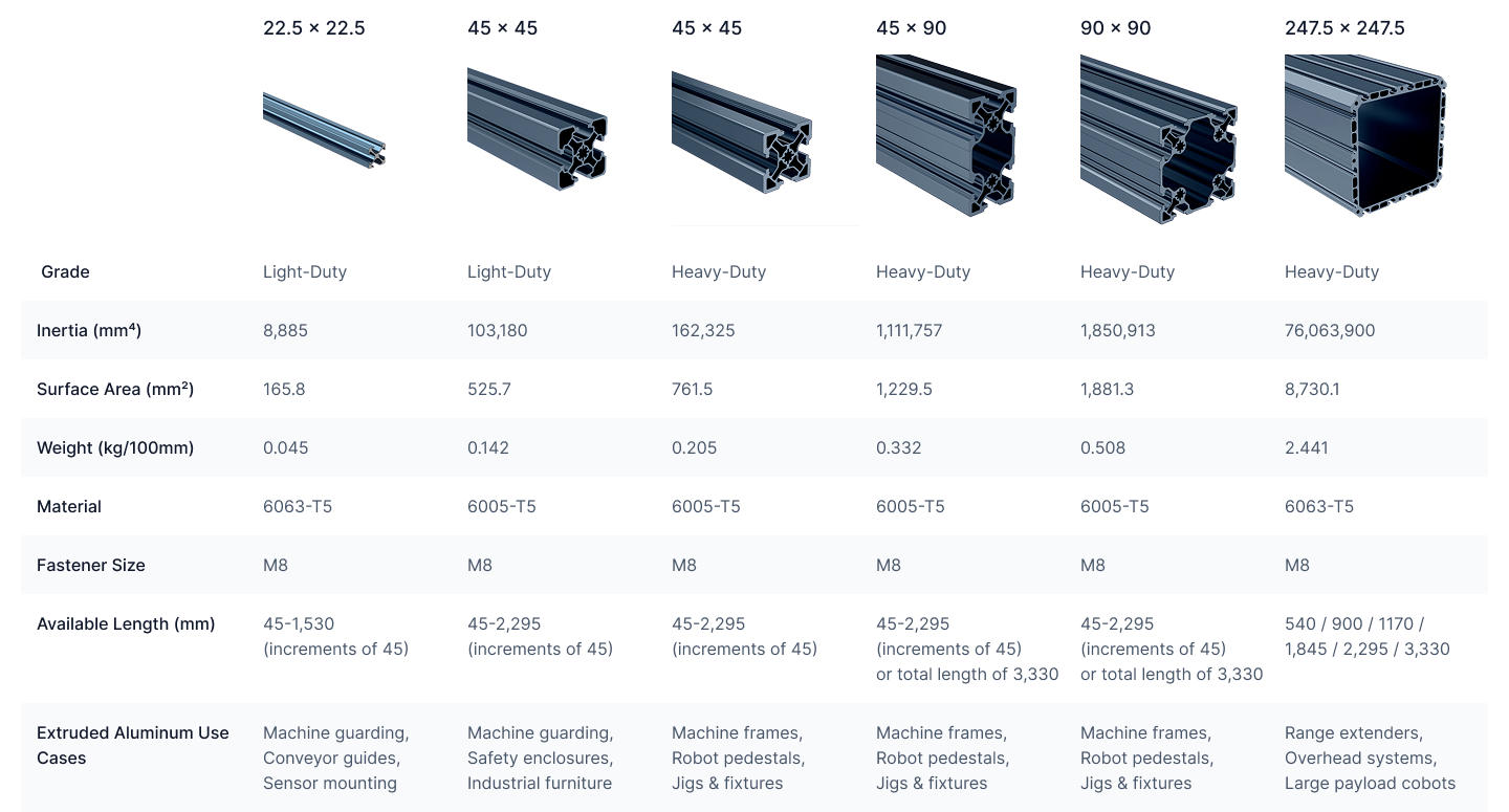
Use XL Double-Walled Profiles for Heavy Robotic Payloads
For cobots in the 20 to 30 kg payload class, standard profiles typically require extensive bracing to meet rigidity requirements, adding assembly complexity and part count.
247.5x247.5mm XL extrusions with a double-walled design were built for this class of application. The double-wall geometry maximizes the moment of inertia for a given amount of material, eliminating the need for complex bracing on overhead 7th-axis systems, gantries, and heavy automation cells.
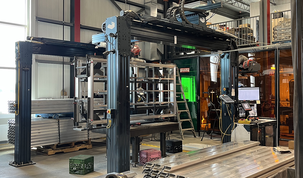
Heavy-duty welding cell built with modular XL extrusions and structural components. Read the case study to learn more.
Strengthening Assembly Joints
Profile selection accounts for only part of a structure’s rigidity. Joint design has an equally significant effect on how loads are distributed.
Joint Orientation Changes Load Capacity
Joint orientation affects how loads transfer across a connection. Moving a gusset from the top of a joint to the bottom increases moment capacity by 13% without changing any hardware. Before finalizing a design, check the extrusion design guide for recommended joint types and orientations.
Do Not Rely on Friction Joints Alone for Heavy Loads
Friction joints rely purely on bolt clamping force. Their load capacity depends on fastener count and installation torque, not profile size or plate dimensions.
For light-duty and secondary connections, friction joints are appropriate. For primary connections carrying significant loads, supplement them with positive-engagement hardware such as corner brackets, gussets, or tension plates.
Verify your joints: The Friction Joint Calculator outputs the maximum load a friction joint can sustain based on your fastener count and torque.
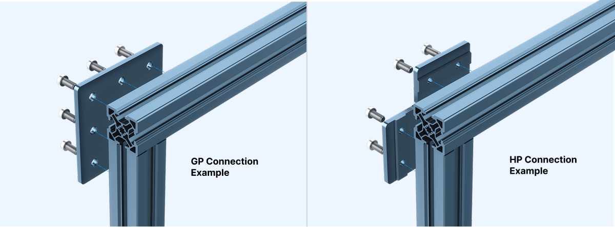
Match Hardware to Load Requirements: GP vs. HP Assembly Plates
Connection plates come in two variants. General Purpose (GP) plates cover most non-critical connections. High Precision (HP) plates support up to 25% more payload and are appropriate where load concentration or precision requirements justify the upgrade.
The practical approach is to use GP plates for the majority of connections and specify HP plates selectively at high-load joints. Vention uses a uniform fastener size across all profile sizes, so the two plate types are interchangeable without compatibility constraints.
Browse assembly hardware: GP and HP plates, corner brackets, gussets, and tension plates in the Vention structural library.
Calculating Safety Factors
A safety factor (SF) is the ratio of the force at which a structure theoretically fails to the maximum allowable working load.
SF = Force at Failure / Allowable Load
The typical recommended range for aluminum extrusion structures is SF 4 to 5. If structural failure poses any risk of human injury, the safety factor must exceed this range.
Run safety factor analysis before finalizing a design. Discovering an inadequate margin at the build stage is significantly more expensive to correct than catching it during profile selection.
Essential Software Tools
Two calculators cover the most common structural validation tasks.
The Deflection Calculator validates a profile against a load case, returning deflection, stress, and safety factor in a single pass. Use it at the selection stage, not after the build.
The Friction Joint Calculator determines the load limit of any joint relying on bolt clamping force. Particularly useful for horizontal joints under vertical loads and connections in dynamic applications where clamping force may degrade over time.
Conclusion
A structurally sound aluminum extrusion assembly is the result of systematic decisions at every stage: selecting the right profile based on rigidity metrics, minimizing tolerance stack-up with precision interfaces, optimizing joint orientation and hardware, and validating the design with the right calculation tools before building.
Used correctly, aluminum extrusion framing delivers structural performance suited to the most demanding industrial automation applications.
***
Sign-up to MachineBuilder and start designing your cell with the right profiles, plates, and fasteners.
Sign-up Now
