CNC Spindle
Router Spindle and VFD Guide
This guide covers the setup of the VFD (variable frequency drive) and spindle combination. This spindle kit allows MachineMotion-equipped Vention assemblies to cut wood, plastics, and other medium-strength materials.
Spindle and VFD Specs
| Specification | Value |
|---|---|
| Max Power | 1 kW at 24,000 rpm |
| Speed range | 6,000*–24,000 rpm |
| Torque | 0.5 Nm from 12,000–21,000 rpm |
| Collet size | ER20 |
| Tool shank diameter | 0.4–13 mm |
| Cooling | Air-cooled with fan |
| Input Voltage | 120 V |
| Control type | Manual / MachineMotion |
| IP rating | IP31 (VFD) |
| Weight (combined spindle and mounting plate) | 4 kg |
Safety
Take the following safety precautions when doing any maintenance or changing the tool:
- Never perform work on equipment that is energized.
- Always follow proper lockout procedures as well as all local safety rules and regulations.
- Use the proper safety equipment at all times.
- Ensure the e-stop is functional and within reach of the operator.
- Routinely inspect the machine to ensure that all bolts are tightened properly, and inspect collets and tools for damage.
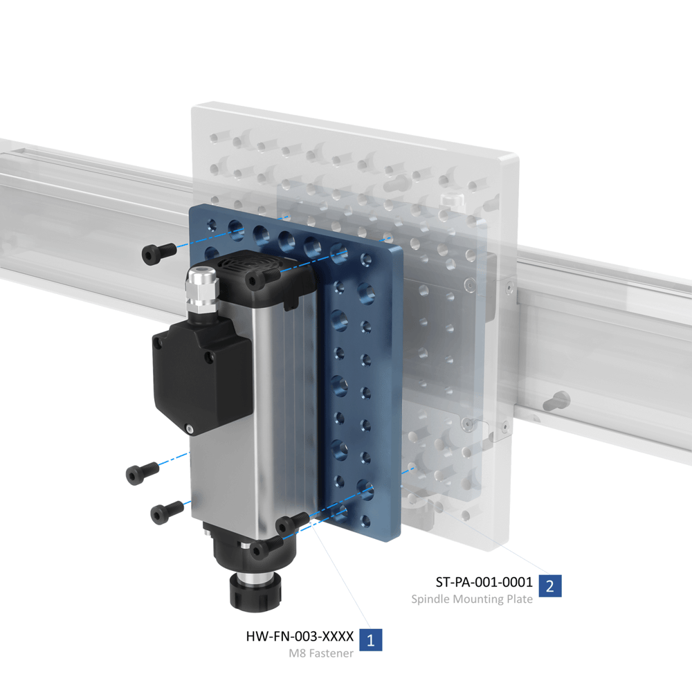
Mounting the spindle
The spindle can be mounted to Vention actuators, extrusions, or plates. Use at least four M8 bolts (included) to attach it.
Mounting the VFD
The VFD (variable frequency drive) supplies the spindle with power and controls its speed. MachineMotion can communicate with the VFD via the digital IO module to control its start and two preset speeds.
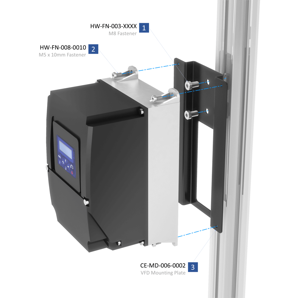
The VFD should be mounted in a dry place, away from material chips and other debris. Leave 125 mm of clearance below the VFD for its electrical cables.
Attach the mounting plate to the machine frame with two M8 x 14-mm bolts (HW-FN-003-0014), then attach the VFD to the mounting plate with four M4 x 10-mm bolts (HW-FN-010-0010).
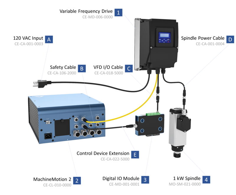
Electrical Connections
Internally, both the VFD and Spindle come pre-wired and configured. To complete the electrical installation, follow the wiring diagram.
Programming the VFD
The VFD parameters control how the spindle behaves. Most parameters are preset for the spindle, but some may need to be adjusted for your application.
You can program the VFD directly from the screen on the unit or use Lenze’s Easy Starter software. Default parameters for our spindle can be found here.
Caution: Incorrect parameters can damage the spindle or VFD.
How to program
The VFD has a keypad through which the spindle can be operated. The keys have the functions listed below.
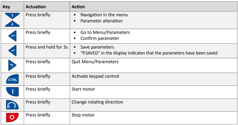
Parameters are values stored in the VFD that control the Spindle and VFD’s operation. They also instruct the VFD on how to power the Spindle. These settings are set by Vention and do not need changing. Parameters have the following format: PXYY.ZZ.
To change a parameter:
- Press the enter button briefly.
- With the up and down arrows, select the group the parameter is in. The group is simply the first digit after “P”. (For example, parameter P400.01 is in group 4.) Press enter.
- With the up and down arrows, select the parameter. Press enter.
- With the up and down arrows, change the parameter value. Press enter to input the change.
- To save the new parameter values, press and hold enter for at least three seconds.
Important Parameters
| Parameter | Description | Range | Preset by Vention |
|---|---|---|---|
| P200.00 | keypad exclusive control enabled | 0 or 1 | 0 (keypad and I/O module enabled) |
| P210.00 | min spindle speed (Hz) | 0 - 400 Hz | 100 Hz (6000 rpm) |
| P211.00 | max spindle speed (Hz) | 0 - 400 Hz | 400 Hz (24000 rpm) |
| P304.00 | CW operation only | 0 - 1 | 1 (CW only) |
| P450.01 | preset speed 1 (RPM) | 6000 - 24000 rpm | 6000 rpm |
| P450.02 | preset speed 2 (RPM) | 6000 - 24000 rpm | 24000 rpm |
Installing cutting tools
A wide variety of tools can be installed in this spindle. Before installing any tool, make sure the tool’s maximum rpm rating is higher than the set speed.
Required tools
The spindle nut and collets hold the tool in the spindle. To change cutting tools, you will need a collet wrench and spindle wrench.
How to change collets
Spring collets need to be changed to match the tool shank diameter. Each collet is marked with the largest diameter it can accept. Each collet size has a range of 1 mm. Collets must be purchased separately from the spindle; your choice will depend on your application.
To change a collet in the spindle nut:
- Remove the nut from the spindle using the two wrenches. Caution: Be careful not to cut yourself on the sharp tool. Never pull on the tool to remove it.
- Loosen the collet nut twice with the wrenches before removing the current tool.
- Apply slight sideways pressure on the collet until it pops out. It should come out easily, if not, try pushing in a different place.
- Push the new collet into place from the top.
How to install tools
- Inspect the cutting tool for damage. Never use damaged tools.
- Install the correct collet size.
- Thread the nut, with collet, a few turns into the spindle. Be careful not to cross-thread the nut.
- Slide the cutting tool into the collet so that the flutes of the tool are just visible. If the tool is inserted too far or not far enough, clamping of the tool will be compromised.
- Tighten the collet nut by hand, holding the cutting tool in place while you do so. Be careful while holding the sharp cutting tool.
- Tighten the nut by holding the spindle in place with the spindle wrench and tightening the nut with the collet wrench.
- Spin the spindle by hand and ensure the tool rotation matches the spindle.
Types of tools
Many types of tools are available for CNC spindles. Some of the most popular ones are listed below.
| Tool Name | Feature Type |
|---|---|
| Twist drill | Holes (note: cannot cut radially, only axially) |
| Flat end mill | Slotting, holes, pockets |
| Ball nose end mill | 3D surfacing |
Besides their shape, end mills are also classified by their number of flutes and types of materials they handle. These factors affect how fast the tool can spin and its ideal speed through the workpiece.
Calculating spindle speed
Spindle speed is an important factor, since it can drastically affect the quality of the cut, the tool’s longevity, and the machine’s productivity. Higher spindle speeds are generally better for productivity and quality. However, speeds that are too high result in decreased tool life.
Spindle speed is measured in revolutions per minute (rpm) and calculated using the diameter of the tool, workpiece material, and tool material. The tool manufacturer will specify its cutting speed, as well as the maximum depth of cut and feed rate.
Spindle speed is:
N (rpm) = CS x 320 / D
CS is cutting speed in m/s (from tool manufacturer)
D is diameter of the cutting tool in mm
Important: Do not set spindle speed below 6,000 rpm, or it may stall when cutting or drilling.
Starting and stopping the spindle
The spindle can be controlled either directly on the VFD or through MachineMotion. By default, the VFD is configured to operate with MachineMotion.
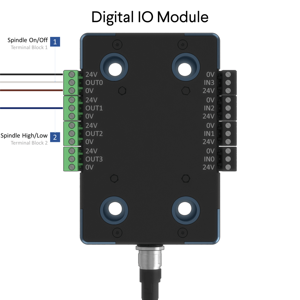
MachineMotion
MachineMotion communicates with the VFD via the Digital IO Module. The function of each output is listed below.
| Output 1 | Output 2 |
|---|---|
| 0 - Spindle Off | 0 - Preset Speed 1 |
| 1 - Spindle On | 1 - Preset Speed 2 |
Enabling keypad control
- Press CTRL briefly.
- LCD will display keypad full CTRL? and then ON or OFF which indicates the current condition.
- Press ENTER to briefly change from ON to OFF.
Starting from the VFD directly
- Press START briefly to start key the spindle.
- Use UP or DOWN arrow keys to change the speed.
- Change directions with the R to F key.
- Stop spindle with the red O key.