Overview
Collaborative robots, such as Universal Robot, FANUC, and Doosan, have become an integral part of many manufacturing processes. Both modular and highly customizable, this technology can be adapted to an increasingly widening range of engineering and manufacturing applications. MAP providers have pushed automation technology to become largely “plug and play” via the availability of productized fixed-height pedestals or telescopic columns, though the design of a custom base or pedestal remains commonplace in today’s market. If users wish to design their own pedestal, the force, weight, and reach of a robot can vary widely and must be accounted for in any given application. There exists a few standard open-source stands in Vention’s public assembly library, but individual verification must be performed against the intended use case. This article will walk through key steps to verify the stability of your custom robot base.
Stability Verification
Two major factors must be considered when assessing the stability of an object – its base width, and the height of its center of mass. Specifically, with respect to robot stands, it is often necessary to add extra weight near the base of the stand, or increase the stand base width, in order to counteract the weight of the robot, its payload, and the powerful motor torque at the base. An assessment routine for the general case of a rolling stand and robot assembly is outlined below. For further advice and project-specific insight, the Vention Applications Engineering team can perform Design Reviews based on their experience and lessons learned.
Calculation Methodology
In calculating robot stand stability, as introduced above, it is important to consider the weight, force, and reach of your robot. In the general case, the stand should be designed for the maximum capacity of the robot at maximum payload, reach, and torque – the maximum loading condition that the stand could be required to withstand. Some users, however, may wish to design a stand to meet application-specific requirements in order to minimize costs. An overview of the calculations required to verify stand stability will be outlined in this section. It is important to note that for this article, all components are assumed rigid. Therefore, deformation under an applied load of any component is not considered. This topic will be addressed in a future article.
The necessary calculations will be illustrated via assessment of the following assembly:
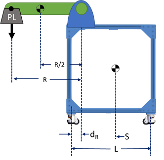 Figure 1: Robot and stand assembly. Note that center of mass has already been designated for each component. For the robot, we assume the center of mass to occur at 50% of the robot’s arm reach, at point R/2. |
First, calculate the center of mass for both the stand and robot.
Two Free-Body Diagrams must now be constructed – for the stand, and for the robot.
The robot’s Free-Body Diagram must include forces acting due to the payload weight at maximum reach, and the robot weight (assumed to act at 50% reach, as shown above). These will be used to calculate the reaction forces (torque and vertical force) acting on the mounting plate that secures the robot to the stand.
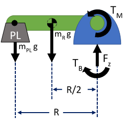
Figure 2: Free Body Diagram of robot. Here, black arrows denote the forces and moments generated due to both the robot's weight and operating payloads. We must calculate TB and Fz, the torque and reaction force generated at the robot mounting plate.
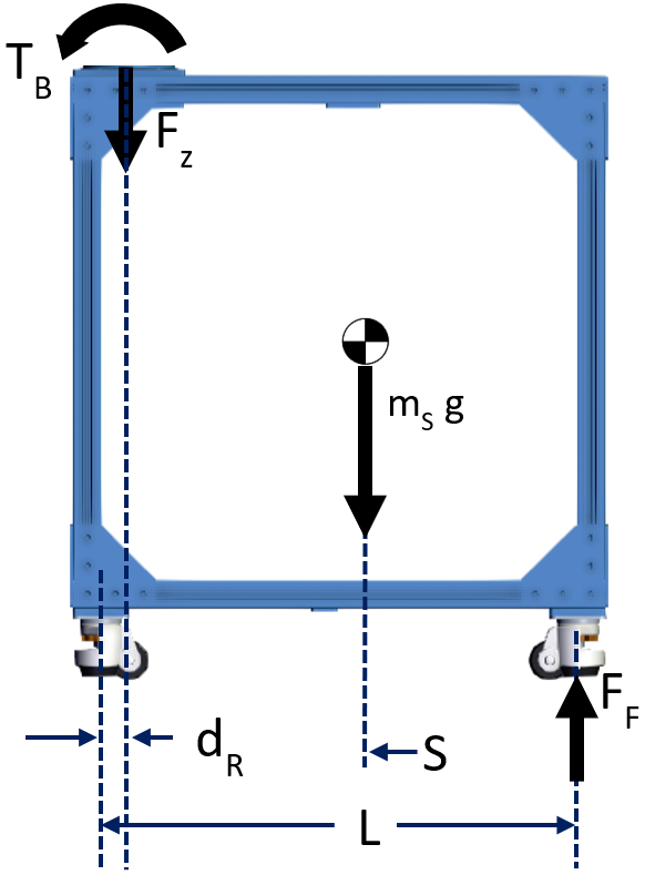
The stand’s Free-Body Diagram must include the stand weight, normal force on each wheel (or ground contact point) of the stand and the reaction forces calculated above for the robot’s mounting plate.
Figure 3: Free Body Diagram of stand. Note that the force and torque from the robot FBD are included here. In subsequent steps, we will calculate FF
We now calculate the reaction forces in the robot FBD. We find the vertical components of the robot’s weight forces, via the equation:
ΣVertical Forces = 0
FZ = mPL * g + mR * g
Then, we sum moments acting on the robot base plate – these are due to robot max torque TM and the weight forces of the arm. The equation in this case is:
Σmoments relative to center of robot base = 0
TB = TM + mPL * g * R + mR * g * R/2Finally, we sum moments acting on the stand as outlined in its FBD to determine the reaction forces at its points of contact with the ground. This is achieved for our example by summing the weight force of the stand, the torque due to the robot’s weight, the robot max base torque, and the torque due to the robot payload, as follows:
Σmoments relative to back POC = 0
0 = m S * g * S + F Z * d R - T B - F F * L
F F = (m S * g * S + F Z * d R - T B) / LIf reaction forces (here, FF) are greater than zero, then the stand is stable. If not, the stand is unstable.
If unstable, design changes must be made. Options include adding weight to the stand or increasing its base width. Here, a Design Review from Vention’s Applications Engineering Team is a great resource - they can propose design modifications based on their extensive experience.
Calculations
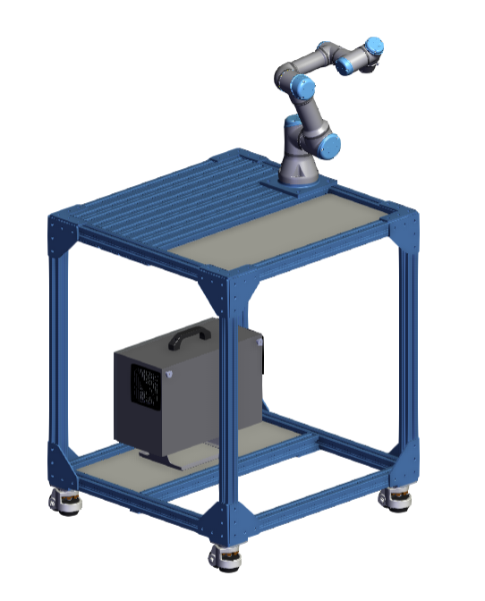
To show an example of these calculations we have selected a Vention Official design for a Universal Robots mobile workstation (UR3e Heavy-Duty Mobile Workstation).
|
Considering the worst-case scenario, these are the known values:
| Max Torque at Robot’s Base Joint (TM) | 56 Nm |
| Max Robot Payload (mPL) | 3 kg |
| Mass of Robot (mR) | 11 kg |
| Reach of Robot (R) | 0.500 m |
| Gravity (g) | 9.81 m/s2 |
Using the above, we can calculate the reaction force and torque at the robot base plate:
|
|
.png)
Knowing the reaction force and torque at the robot base plate, we can verify the stability of the stand:
| Mass of Stand (mS) | 45 kg |
| Robot Base Plate Reaction Torque (TB) | 100 Nm |
| Robot Base Plate Reaction Force (FZ) | 140 N |
| Stand Centre of Gravity Position (S) | 0.370 m |
| Distance between Robot Base and Stand PoC (dR) | 0.045 m |
| Length of Stand (L) | 0.765 m |
|
.png)
We can also optimize for a shorter stand by setting the floor front point of contact reaction force (FF) to zero, and then find the safety factor of the original design:
|
.png)
Conclusion
Robot arms require structured environments to operate: they need a rigid base for support and effective fixturing for their workspace and tools. Another critical design consideration is to guarantee the stability of the overall assembly. As described in this article, both gravity and motor torques need to be considered. By understanding the various parameters that make stands unstable, designers can engineer their assemblies and optimize for both safety and cost.