Digital I/O Module Datasheet
Contents
Overview
The Digital I/O Module v2, CE-MD-001-0000__2, extends MachineMotion 2’s functionality with 4 (NPN or PNP) inputs and 4 PNP outputs. This plug-and-play module only requires a single connection to the MachineMotion 2 controller. Compatible modules, such as the Power Switch (CE-MD-005-0000) & additional Digital I/O Module v2 modules can also be daisy chained to each other, making it possible to connect up to eight modules per MachineMotion 2 controller. For details on Vention’s Digital IO Module V1, refer to the ‘Documentation for Previous Product Versions’ section at the bottom of this page.
Features
- 4 Inputs compatible with NPN and PNP sensors
- 4 PNP Outputs
- Connects (daisy chain) with compatible modules
- Configurable address
- Plug-and-play access from the Control Center, MachineLogic, and Python API
Programming Options
Program the Digital I/O Module v2 using [MachineLogic] or the [Python API]. It can also be accessed from the Control Center.
Technical Specifications
General Specifications
| Part Number | CE-MD-001-0000__2 |
|---|---|
| Certifications |
|
| Weight | 1.5 kg |
| Dimensions | 60 x 88 x 150 mm |
| Material |
|
| Operating Temperature | 0 to 40°C |
| Included in the Box |
|
Performance and Other Specifications
| Specification | Value |
|---|---|
| Digital input impedance | 5kΩ |
| Digital input active NPN voltage range | < 6V |
| Digital input active PNP voltage range | > 18V |
| Digital output maximum current | 0.1A |
| Maximum Power consumption | 12W |
| Latency (with 2 modules connected to the MM2 controller) | 125ms max. |
Latency has been obtained by connecting a digital output port to a digital input port, and by measuring the delay between requesting the change of output state and reading the change of input state.
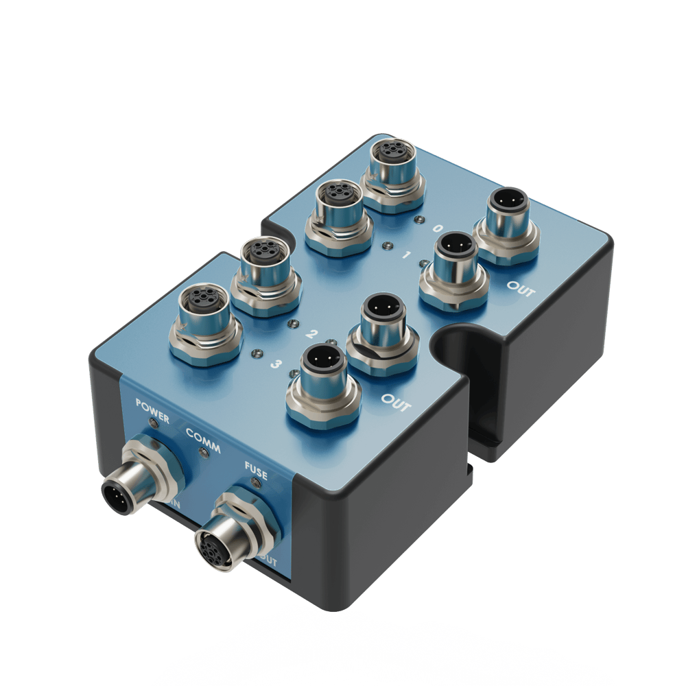
Physical Interface
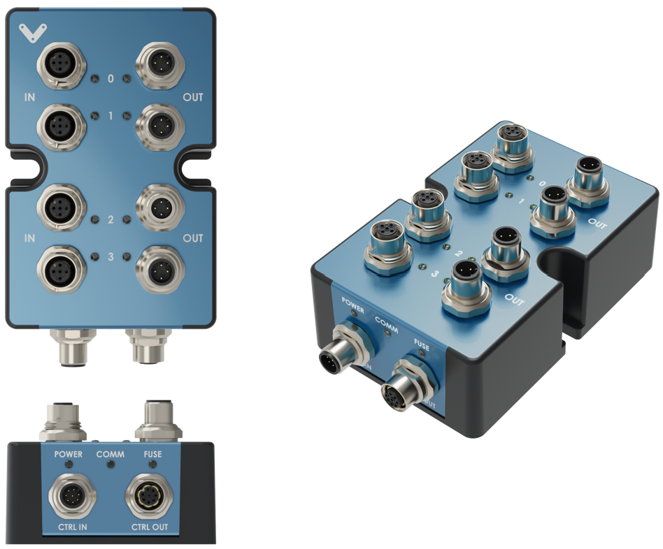
CTRL IN Male M12 connector pinout
| Pin | Description |
|---|---|
| Pin 1 | 24 VDC (input) |
| Pin 2 | Ground (input) |
| Pin 3 | RS-485 A (input) |
| Pin 4 | RS-485 B (input) |
| Pin 5 | Reserved |
| Pin 6 | Reserved |
| Pin 7 | N/A |
| Pin 8 | Reserved |
CTRL OUT Female M12 connector pinout
| Pin | Description |
|---|---|
| Pin 1 | 24 VDC (output) |
| Pin 2 | Ground (output) |
| Pin 3 | RS-485 A (output) |
| Pin 4 | RS-485 B (output) |
| Pin 5 | Reserved |
| Pin 6 | Reserved |
| Pin 7 | N/A |
| Pin 8 | Reserved |
IN Female M12 connector pinout
| Pin | Description |
|---|---|
| Pin 1 | 24 VDC |
| Pin 2 | Input |
| Pin 3 | Ground |
| Pin 4 | NC |
OUT Male M12 connector pinout
| Pin | Description |
|---|---|
| Pin 1 | 24 VDC |
| Pin 2 | Output (100mA max.) |
| Pin 3 | Ground |
| Pin 4 | NC |
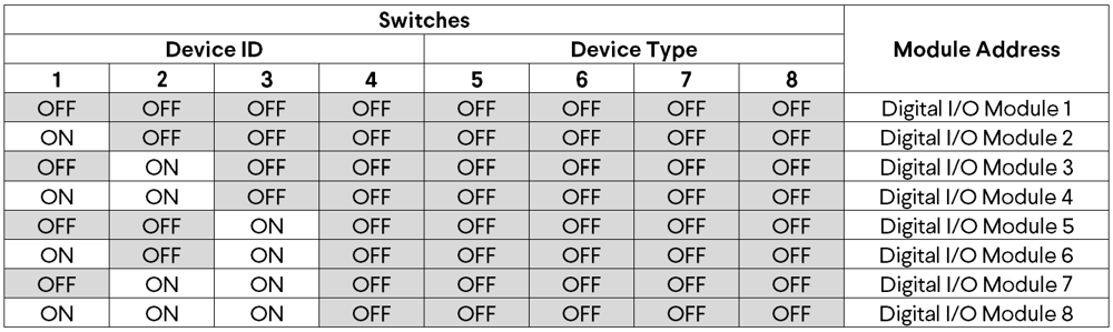
Digital I/O module v2 address configurations
Below are the valid address configurations that can be used for the Digital I/O module v2
Valid address configurations